Vinc_Vega
-
Posts
641 -
Joined
-
Last visited
Content Type
Profiles
Forums
Events
Everything posted by Vinc_Vega
-
As there are a few on the market, please tell us exactly what ESP32 board do you use. Probably a link to the supplier would do it. Regards, Vinc
-
If you still have issues to talk to the MCP23017, you may have a look how I described usage of that pin extender within my VHF FM radio panel. Btw. the tryToSendDcsBiosMessage commands can be replaced by your sendDcsBiosMessage code. Have a nice weekend, Regards, Vinc
-

Molevich’s Mi-24P pit now on its own Discord
Vinc_Vega replied to molevitch's topic in Home Cockpits
That's a good question from the mechanical point of view. And: why always a parallel way for information (here: this forum and discord) ? Regards, Vinc -
Need help with programing tm1637 6 digit 7 segment display
Vinc_Vega replied to Hatiz's topic in Home Cockpits
@Hammer3246 Have you already tried to declare two display objects? #include <TM1637TinyDisplay6.h> TM1637TinyDisplay6 display(4, 5);// Create a display object -> display for frequency TM1637TinyDisplay6 display2(11, 12);// Create a second display object -> display2 for channel Talk to both displays like so display.clear(); display2.clear(); The last lines of above code than must be changed in somethin like that // ---- edited code for a F-16 UHF CHAN Display display2.showNumber(digit7, false, 1, 0); display2.showNumber(digit8, false, 1, 1); // ---- end of edit Regards, Vinc -
Need help with programing tm1637 6 digit 7 segment display
Vinc_Vega replied to Hatiz's topic in Home Cockpits
Hi Hammer, The above code doesn't include a Preset Channel display. If you want to have that display e.g. to the last two digits of an already used 8 digit module, you can plug in additional lines to my function"show_UhfFrequency()". See below code snippets for markings "edited code for a F-16 UHF CHAN Display" to see where the changes have to be in the sketch. Beware of, that I neither touched the rest of for the A-10C UHF code nor tested the edited sketch with hardware. Note, that an additional variable "String uhfChan" is created in the head of the sketch to convert the output String of the Channel to an integer and use the "showNumber" feature of the TM1637 library in the end. Regards,, Vinc -
Strange! Please tell us more in detail what microcontroller and display driver are in use and if you modified the hardware. Regards, Vinc
-
You just deleted to much from the root sketch. Put the following line in front of the DCSBIOS_DISABLE_ SERVO definition: #define DCSBIOS_DEFAULT_SERIAL As the Serial port is used by DcsBios, you furthermore may uncomment the DEBUG definitions and Serial statements in your sketch to unblock communication. Regards, Vinc
-
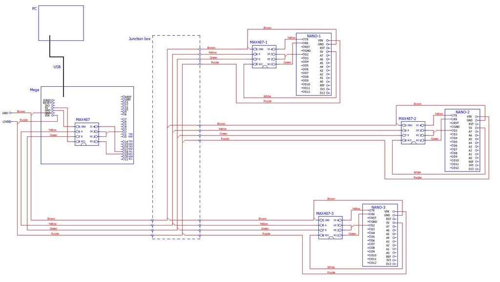
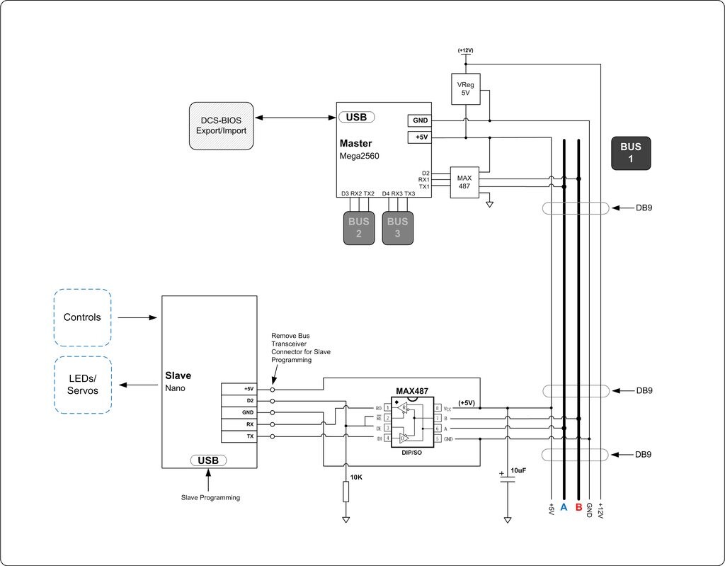
@JohnnyChicago The images from the first page of this post show similar graphics, but maybe a little bit clearer. The Slaves must be connected via the RS485 bus only and not to the USB port at the same time. It also may help to use a common power supply for all Arduinos. As I had difficulties to directly link the pictures, here they are again. For the software, you have to use the sketch from Arduino\libraries\DcsBios\examples\RS485Master\RS485Master.ino for the Master ONLY (Mega). Have a look at line 5 of the sketch RS485Master.ino #define DCSBIOS_RS485_MASTER If using a single RS485 bus, you may comment out the UART definitions as follows #define UART1_TXENABLE_PIN 2 // #define UART2_TXENABLE_PIN 3 // #define UART3_TXENABLE_PIN 4 The sketches from Arduino\libraries\DcsBios\examples\RS485Slave\RS485Slave.ino are for all your Slaves and therefore, have to be adjusted in line 6, so that each Slave has a unique identifier. The example in RS485Slave.ino is for Slave No. 1 #define DCSBIOS_RS485_SLAVE 1 For a second Slave you have to use another Slave number, like #define DCSBIOS_RS485_SLAVE 2 and so on ... Regards, Vinc

-
Hi Les, That's why I mostly skip Google's answers, containing posts of the Arduino forum Regards, Vinc
-
@lesthegrngo What @No1sonuk wanted to point out is, that a normal "delay()" command is in Milliseconds, therefore it is not the same time span if you'd use "delayMicroseconds()" (see your first sketch). Regards, Vinc
-
@JohnnyChicago No, you can hook up to 128 slaves to one bus. But nobody has experience with that amount. Just remember to give a slave it's unique number within the net. You enable the other pins at the Mega to have two more buses. Regards, Vinc
-
Hi Les, do you think about something like this? https://www.adafruit.com/product/400 Regards, Vinc
-
@OldFlyer An ESP32 is much more powerful than a Mega but can only be connected by USB. The Mega may work with the RS485 bus (see other posts). A Nano hasn't the memory to serve the 256x64 pixel display. For the display itself a cheap one from AliExpress will do it after conversion to 4 wire SPI bus. Regards, Vinc
-
@Snakedoc The ultimate answer is: Yes, I know. But there's no way at the time. After looking into the respective DCS folder for the PFLD, your impression of a "still WIP" status unfortunately may be true, because of it seems to be implemented more or less as placeholder yet. But the real problem is, that the "export translation file" for DcsBios (F-16C_50.lua) even does not list the PFLD at the time. As the DED code within that lua-file alone comprises of almost 1.360 lines of code, it probably makes no sense to implement the PFLD in the current status (WIP). Nevertheless, you may ask for support in the developer's Discord channel and tell us their answer Regards, Vinc
-
@Snakedoc Thanks for the feedback Sorry, I'm not so familiar with the F-16. I have the module but for the DED display just re-wrote the code to make it compatible with the u8g2 graphics library, built a new font and put in the logic to decode the inverted characters. If the PFD (primary flight display?) has no DcsBios support (e.g. you can't find it in Bort), there is no good chance to write code for it at the time. Regards, Vinc
-
@Snakedoc Finally my SSD1322 display arrived from Aliexpress. Nine days from China to Germany, normal shipping, that`s great! Display arrived the factory style, configured for the 80xx parallel bus. Like already written here in the posts, to convert it into 4 wire SPI configuration, resistors R5 and R6 had to be swapped. As this is at zero Ohm, R6 carefully may be snipped off the board and jumper R5 could be bridged by a solder blob. Connection to the LOLIN ESP32 S2 Mini has been done as already proposed: OLED -> LOLIN S2 Mini 1 -> GND 2 -> 3.3V 4 -> 7 CLK hardware SPI 5 -> 11 MOSI hardware SPI 14 -> 6 DC 15 -> 8 RST (may be changed to any digital pin) 16 -> 12 CS hardware SPI The display is quick responsive to the F-16 DED with hardware SPI and the driver must read: U8G2_SSD1322_NHD_256X64_F_4W_HW_SPI u8g2(U8G2_R0, /* cs=*/ 12, /* dc=*/ 6, /* reset=*/ 8); I think that this display may replace that in my CMSP panel, so I did a quick sketch and custome fonts for the A-10C that already looks great. Please find below the adapted F-16 DED sketch for the S2 Mini and SSD1322 display. Regards, Vinc
-
Btw. my ULN2003 stepper board can be supplied by the usualy Arduino +5V port. https://www.pollin.de/p/daypower-schrittmotor-set-s-spsm-5v-310543
-
@lesthegrngo Hi Les, I would try to bring a calibration routine into the Setup() section. 1) Check if an end switch is pressed: a) If switch one is pressed, set the step counter to zero (closPos) b) If switch two is pressed, set the step counter to 200 (stepsToGo) 2) While no switch is pressed, move forward (1 step) until switch two is pressed (you may run more steps than one per loop, just trial and error) 3) Set the step counter to 200 steps (You also may run the stepper backwards until switch one is pressed and then set the counter to zero steps) 4) Setup your calibrated buttonStates and leave the while loop In the loop() section you that repeatedly ask which switch is pressed for the corresponding action I think it's better not to use the buttonStates within the Setup() section of the sketch, because it only goes once though it, and therefore, especially in the While loop the pins directly are read out. You then may use the buttonStates in the Loop() section as usual. Beware of, that the above sketch is not faile safe, e.g. if both buttons are pressed, and not debounced. Regards, Vinc
-
@CR77 Don't give up. Use the driver statement I proposed above with your Mega2560. An Nano hasn't enough memory to drive that large display. Have a nice weekend, Vinc
-
@CR77 there is an u8g2 statement missing within my proposed driver. I corrected the above postings accordingly. Sorry for that! U8G2_SSD1322_NHD_256X64_F_4W_HW_SPI u8g2(U8G2_R0, /* cs=*/ 53, /* dc=*/ 6, /* reset=*/ 8); Regards, Vinc
-
@CR77 What we need to help you isn't the code already provided but the compiler error messages. Your display does not show anything because the driver uses only 256 kB instead of the full buffer (2048 kB). What microcontroller are you using? (UNO, Mega2560, ESP32 ...) Regards, Vinc
-
@CR77 The proposed line already is excluded from compilation (see double slashes infont of the line "//"). Just use the right declaration for the display driver. Look for the included "_NHD_". U8G2_SSD1322_NHD_256X64_F_4W_HW_SPI u8g2(U8G2_R0, /* cs=*/ 53, /* dc=*/ 6, /* reset=*/ 8); Regards, Vinc Edit: I adpted the code in the above post for the questioned SSD1322 displays
-
Hi @uncino sorry, that I can't reply while at work. But fortunately you made it, probably by reading all the hints here in the postings Congratulations! I believe that you don't connected pin 3 and pins 6 to 13 of the display to the chip. Pin 5 DIN equals MOSI or SDA from the above post. Pin 4 CLK is the same like SCK / SCL from above. Pins 16 CS, 15 RES and 14 D/C are simple to know. Pin 1 goes to GND and pin 2 pulls +5V. Do not use the 3.3V output of the Mega, as the level signals anyways are at 5 Volt. Best regards, Vinc
-
Here is a sketch, adapted to MEGA2560. Response is good if using the hardware SPI pins. Any regulary UNO has not enough memory to store the sketch. Pinout for the MEGA2560 hardware SPI driver: MOSI: 51 (SDA) hardware SPI SCK: 52 (SCL) hardware SPI SS/CS: 53 hardware SPI DC = 6 (may be changed to any digital pin) RST = 8 (may be changed to any digital pin) U8G2_SSD1322_NHD_256X64_F_4W_HW_SPI u8g2(U8G2_R0, /* cs=*/ 53, /* dc=*/ 6, /* reset=*/ 8); I adapted the sketch for a MEGA2560, you have to adjust your own display driver (see above) Hint: you won't see anything on your display after successful upload, else commenting the “String(line1) ; String(line2); …” line and un-commenting the “String(line1) = …” to “String(line5) = …" section. Edit: Code adapted for questioned SSD1322 displays
-
Yes, the number in square brackets is the position within the array (frequency string). Second number in the setChar command is the digit of the display. (First number is the number of the Max7219 chip, as you may use 8 of it. If you only have one chip, number is always 0) Best greetings my friend!