Smyth
-
Posts
51 -
Joined
-
Last visited
-
Days Won
1
3 Followers


-
I wouldn't say actively chosen, as much as directly selected by the current position of the switch. In the manual, there is no mention of any logic other than scanning based on the position of the switch. I would think any kind of default behavior would be called out specifically, however it would take input from the developers, or a real SME to be 100% sure.
-
You only need to press the NWS button again to reject a false or undesired target. The system memorizes that range and eliminates it from the next few scan cycles (+/- 200ft), effectively forcing the system to switch targets. Leaving the cage mode with weapon select knob or AA button does not cancel the lock. That is the well thought-out part. The part that mystifies me is why they changed the software with 'OFP005' to require selecting a scan corridor using the weapon select switch. The original setup sounds like a pretty simple and intuitive system. Point plane at target, lock it, shoot it. Maybe if I was a real 80s fighter pilot this would make sense, but I just can't imagine how it is worthwhile to force the operator to select the wrong weapon in order to use the center scan corridor 90%+ of the time, then hopefully remember to switch back to the weapon that actually needed radar lock. Honestly having read the IRL docs I was a little disappointed to learn that HeatBlur are implementing OFP005 on 'our' F4. The original version just seems better. Hopefully I'm wrong about that.
-
Part Three – Conclusion: Here I will editorialize a bit. Without seeing the lift, drag, and thrust models used inside the flight model, it’s hard to tell if the incorrect CL curve and the incorrect turn-time curve are related. Either way, they both need to be fixed. In absolute terms the maximum lift is a bit too high, but that is not the problem I’m concerned about. The virtual pilot does not ‘feel’ it. What is immersion-breaking once you notice it is a jet with a small, low-aspect ratio wing generating peak lift at 15 degrees of AoA or less. Those are straight-wing propeller plane angles. Additionally, the way CL increases at low speed reduces the normal variation of AoA with speed. Practically speaking that will degrade the responsiveness of the aircraft when the pilot tries to control airspeed correctly with AoA, especially on landing approach. I think there is a reason so many DCS players struggle to make stabilized landing approaches in the -21. Likewise the steady turn rate being slightly too high is not the main problem. The main problem is the shape of the curve. On the real MiG-21, slowing down below M0.5 decreases performance. On the simulated MiG-21 right now it does not lose any performance, and experienced players know to hold AoA in the red and slow down to stall speed for maximum turn rate. This becomes almost a complete inversion of reality when thinking of tactics and flying technique. I don’t want to beat a dead horse much longer, but it’s worth saying again that there is not even one supersonic jet known to behave this way. There are too many diagrams to show here and many of them I am probably not allowed to post. Instead I will just list the fighters that we either see in DCS or know from public data do not turn faster at minimum speed, and leave finding the charts I am looking at as an exercise to the interested reader: MiG-19 MiG-23 MiG-29 Su-27 F-4 F-5 F-8 F-14 F-15 F-16 F-18 F-20 F-100 F-104 Mirage III Mirage F1, Mirage 2000 JF-17 Draken Viggen That is a long list, but alone does not mean the MiG-21 cannot have a second turn rate peak at its stall speed. What is does mean is that this behavior is only believable if specific data backs that up. The specific data we do have does not. Lift_uua_28_clean_2.trk Fishbed_sustained_7511_r3s.trk
- 5 replies
-
- 37
-

-

-
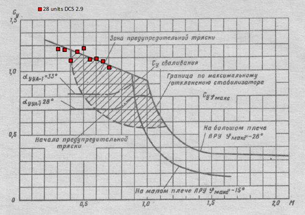
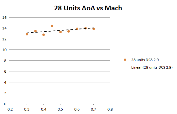
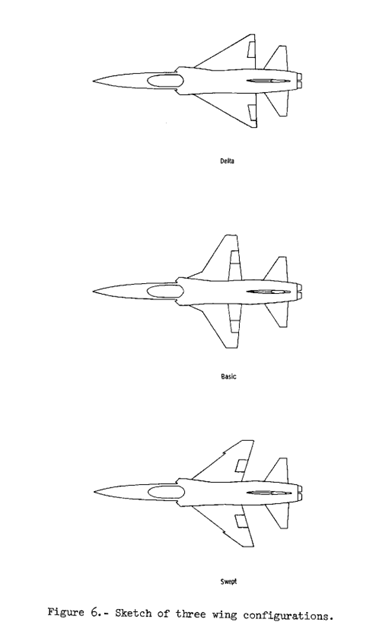
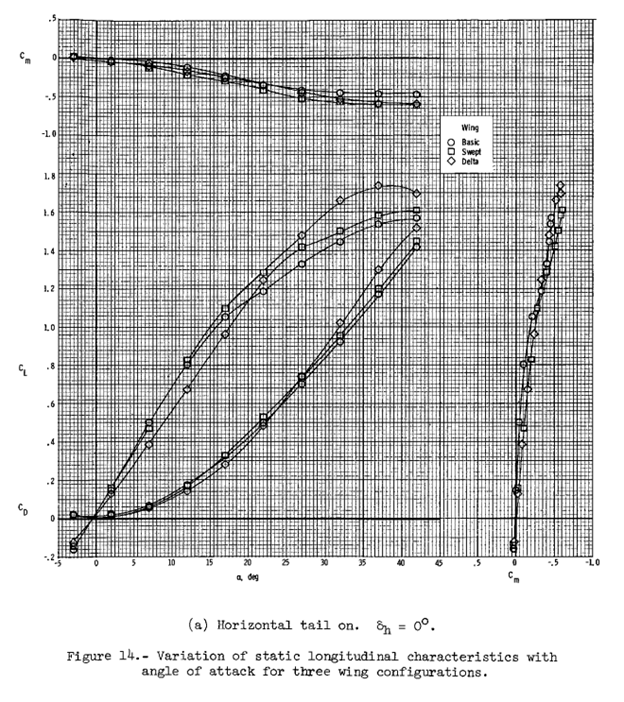
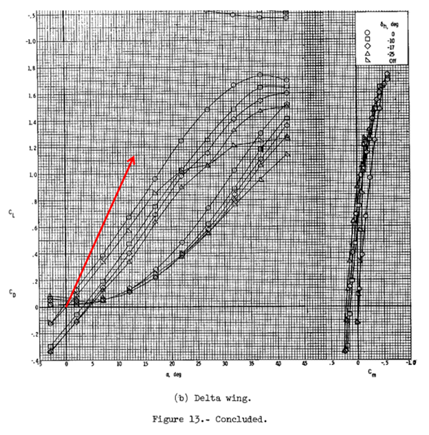
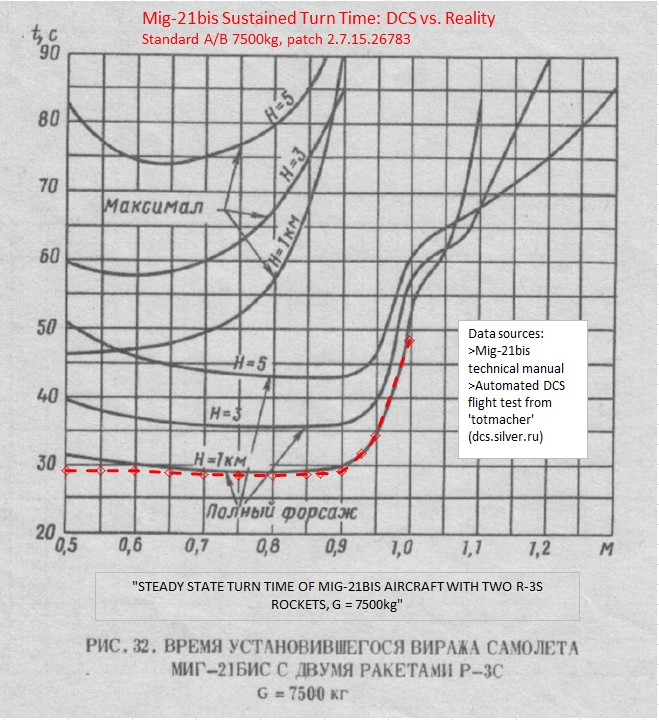
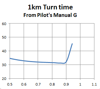
Part Two – DCS: With a basic grasp of the real-world data, it is time to look at the behavior of the MiG-21bis module in DCS World. Let’s start again with coefficient of lift. This is straightforward enough to measure. Perform a decelerating turn at constant AoA, record the altitude, TAS, and G-force at a few different speeds, then calculate CL at each point. My result is not as clean as it could be, but it says all that needs to be said. I’m confident this is accurate because it matches what several other forum members have measured in the past. In very simple terms, the lift at 28 units indicated AoA is swapped with the line of maximum lift, just like the chart in the Russian language tech manual. According to all the evidence from part one, this is not correct. 28 units is not even the maximum lift in-game. There are two possible explanations: The ratio of indicated AoA units to true AoA degrees on UAA-1 in the DCS MiG-21bis simulation is not constant and increases rapidly at low speed. The parameter of lift vs mach in the DCS MiG-21bis simulation is not correct. The first possibility can be quickly eliminated because the ratio of AoA units to degrees in-game currently decreases slightly at lower Mach numbers. Here is my measurement at 28 units. Other forum members have measured this in more detail. At low speeds, this is about 13 degrees of true AoA generating CL of at least 1.15 --- an extremely steep lift curve for a wing with an aspect ratio of about 2.2. How steep is 1.15/13 exactly? There is no wind tunnel data easily available for the MiG-21, but we can sanity check this against abstract literature, or other delta wing designs. Fortunately NASA makes this easy. They reported on a scale model test in the 1970s comparing the F-5A wing with some other planforms (https://ntrs.nasa.gov/citations/19740018330). More specifically, they tested an un-cambered tailed delta wing with AR=2.1, and a swept wing with AR=2.8. While the report does not say “Fishbed” or “Phantom”, just take a look and judge for yourself what they were thinking of (in 1974 America): The real MiG will vary slightly from this proxy, but not by much. Here is the CL NASA measured for each wing: Remember what I said about drafting errors? Fortunately NASA only connected two dots incorrectly, and the legend is correct as confirmed by other pages of the report. Here is the page for the delta specifically. I have added where the DCS MiG-21 lands. It is over 60% steeper, even assuming the chart in the MiG-21 manual represents tail installed but without deflection. Notice also that the test CL at 13 degrees is 0.72, just about equal to what the manuals claim for 28 units. Coincidence? Maybe. This is only one data point, so it’s also good to sanity check with the expectations of abstract literature. Fortunately delta wings are very well studied, and at this point almost a standard teaching aid for wind tunnel tests. Using the Polhamus model for vortex lift (https://ntrs.nasa.gov/citations/19670003842), I get CL(15deg) = 0.76 for AR=2.1. That matches perfectly to the line for δh = “off” in the chart above. The lift curve of the DCS MiG-21 is simply not plausible. CL/deg of 0.09 belongs to a completely different category of wing. One might reasonably assume that an implausible lift curve slope will result in other implausible behavior. In other words, it’s now time to look at sustained turn rate. This module is quite famous in the multiplayer PvP community for sustaining its best turn rate at minimum speed, but proponents often point out that the real sustained G charts do not go down below 0.5 Mach. True enough, but really beside the point. We can look at the turn time chart and see the problem without extrapolating anything. To illustrate, I’m going to borrow data from the extremely useful compilation of automated testing by @totmacher at dcs.silver.ru. I hand-flew some tests before my two week trial ran out to sanity check that the extreme low speed performance is not an artifact of the automated testing. A .trk is included, but the precision of the automated test is simply far better than what hand flying can achieve. If more data is really needed to illustrate the problem, I know some other community members have been collecting extensive hand-flown data recently. Now here is an overlay of that automated test against the tech manual turn-time chart for standard afterburner at 1000m altitude: Turn rate at higher speeds matches OK (probably this is where it was validated in development). To see the real problem, just look at the slope of the curve at M0.5: The turn rate of the real aircraft is slowing down The simulation is not We also know that the turn rate even gets faster (turn time goes down) below that speed in the simulator, but it’s not necessary to look there when the problem is already evident. Showing data from in-game below the minimum speed of the IRL plots seems to generate a lot of controversy for some reason, so I am avoiding that.

- 5 replies
-
- 32
-
-
-
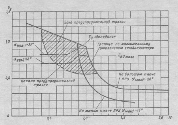
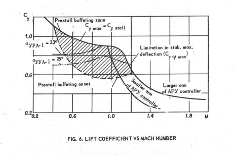
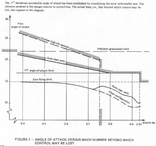
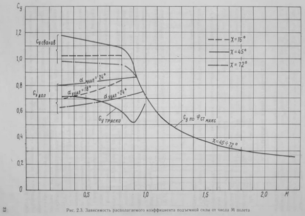
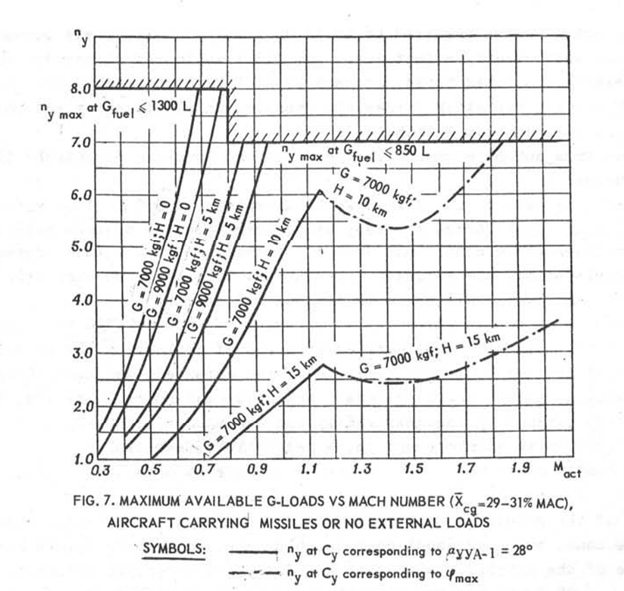
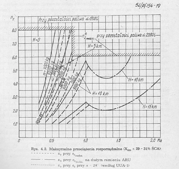
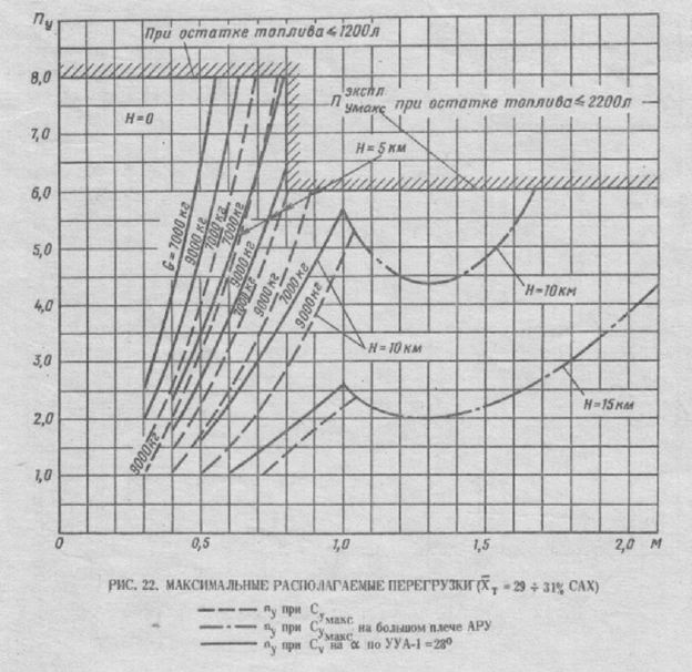
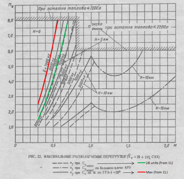
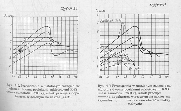
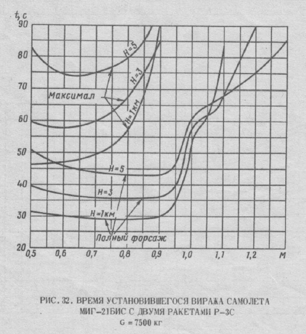
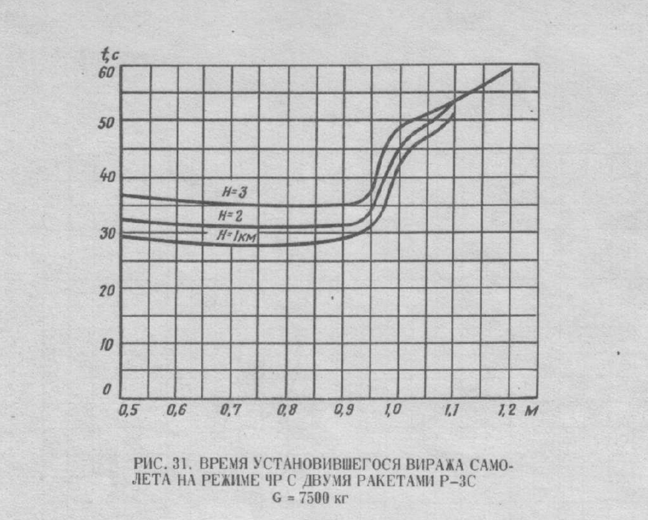
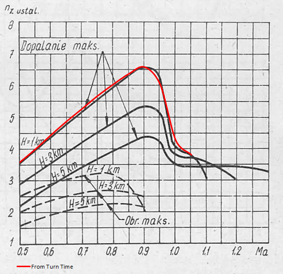
I finally got around to trialing the MiG-21 recently and was not surprised to find some issues with the flight performance model; they have been discussed before many times and various data has been shared. With that in mind, it was odd to hear through the Discord grapevine that Magnitude 3 does not believe there is enough evidence to show anything wrong. Maybe that was a miscommunication, or maybe the good data has been lost in years of noise on the topic. Therefore I have made an attempt to summarize the key points in one place. This will take some time to explain, because the data available in the public domain is confusing and sometimes appears contradictory. It takes careful comparison along with some calculation and context to sort out what is real. For that reason this manifesto report will be split into three parts: What real world data is available in the public domain, and what is useful. What in-game data can be easily measured, and how it compares to those real world sources. My opinions on what it means for the game (I will try to keep this last part short) Part One – the manuals: Unlike some other contemporary fighters, there do not seem to be any flight test reports or “practical aerodynamics” textbooks in the public domain for the MiG-21. Fortunately many operational manuals contain some level of useful aerodynamic information. The ones already available on the internet for the -21bis include: Soviet technical description manual Polish technical description manual Pilot’s flight manual in Serbian (for Yugoslavia), English (for Arab states), and Polish Throughout these manuals there are four key charts repeated which are relevant to a discussion of turn performance. Coefficient of Lift, Available G Sustained G Sustained turn time Unfortunately the same chart does not always agree between manuals. However by cross-examining the various documents we can rule out some obvious miss-prints, and establish which charts are useful. To enable this cross examination, it is important to realize that these four charts are really only two sets of data, with each pair of parameters related by well-known equations: Normal acceleration ‘Ny’ = (CL * Aref * .5 * ρ * v2)/(m*g) Turn Time = 2π / (sqrt(Ny2 – 1)*g/v) Let's start with CL, because is the most basic property of the four. Fortunately the different MiG-21 manuals all basically agree on this one. The relevant graph gives non-dimensional lift coefficient versus angle of attack in arbitrary units. These units are not really degrees, but some function proportional to the true angle of attack. The flight manuals do not specify exactly what that function is. Tech manual version: Pilot’s flight manual version: The hand-drawn lines are slightly different between versions, but they show the same two expected trends: Coefficient of lift is almost constant for constant AoA, until compressible flow effects become significant around M0.7 This is expected by definition of CL as a non-dimensional coefficient valid for incompressible flow. Maximum lift increases at low speed with increasing AoA of stall. For fast jets (unlike "normal" aircraft) 'stall' is often a function of loss of stability, sometimes combined with a limit of horizontal tail effectiveness. Loss of stability does not normally correspond to a fixed AoA. In other words, both of these trends are the expected behavior for a supersonic fighter with a low aspect ratio wing. To emphasize that this is the expected behavior, here is a similar plot for a similar jet (Mirage F1) with AoA on the vertical axis. Note that just as the MiG-21 manual quotes 33 units as the stall AoA, the Mirage manual quotes 17 units. On both aircraft the true stall AoA is higher than the quoted limit over most of the envelope. Now also the same plot for the MiG-23. With wings swept (45 and 72 positions) the coefficient of lift increases slightly as Mach increases for a fixed AoA. The line of maximum lift is not tied to a fixed angle, and instead increases with decreasing speed. All this is just like the MiG-21. Charts for other aircraft are obviously not directly relevant to the performance of the MiG-21, but I include them because it is important to have context for what is normal and plausible. Next it’s time to compare graphs of available G, which should all agree with the Cl figures. Unfortunately this is not quite the case. Pilot’s flight manuals show only 28 units AoA: Polish tech manual shows two unknown lines. The chart legend mentions 28 units and maximum lift, but they are unhelpfully both dashed lines, while the chart uses one solid and one dashed line. Helpfully enough the dashed lines do match the solid lines for 28 units in the pilot’s manuals seen above, which suggests that “CZmaks” was intended to be the solid line in this drawing. It would be nice if the Russian language tech manual clarified this for certain, but sadly it does not. The lines are clearly the same as the other versions, but the legend is reversed with 28 units now shown above the ‘maximum’! Something is wrong, but how to tell for sure which version is correct? The next step is to convert CL to G and see which version the CL plots match. I will use the tech manual chart mostly because it is linear which makes things easier. Red line at maximum lift CL = 1.32 – (0.4*M) Green line at 28 units is a constant CL = 0.7 Lift calculated from those CL at sea level standard conditions and 23m2 reference area overlays perfectly with the lines in the manuals, only the labels for “28 units” and “maximum” are reversed in the Russian-language print. The green line also matches the one labeled “28 units” in the pilot’s flight manuals. Considering that the CL plot agrees between all manuals, that it agrees with the plausible expectation set by other jets, and that the pilot’s flight manuals all show lift at 28 units matching the CL plots at 28 units, there is not much ambiguity left. Whoever drew this legend by hand in the 70s flipped the label of the lines by accident, just like the draftsman of the Polish manual accidentally drew different lines on the plot and the legend. Drafting errors are common in old technical documents, and context clues are the key to resolving contradiction. Keeping the possibility of mistakes and contradiction in mind, it’s time to look at sustained turn performance. All the manuals provide sustained G charts for both standard afterburner and emergency afterburner at 7500kg with 2x R13 series AAM. Pilot’s flight manuals: Tech manuals: This new discrepancy is obvious right away. The tech manual shows around 6.5G peak for standard afterburner, while the flight manual shows 6.5G peak for emergency afterburner. The other lines are all similarly offset. To get more context we can try to cross-examine against the sustained turn time plots, although they only exist in the tech manuals. Here are military (dry) thrust and standard afterburner: And emergency afterburner: For comparison I digitized the 1km line for standard afterburner, converted from turn time to turn rate, and then turn rate to sustained G force in the flight path axis using the equations mentioned above. It matches quite well. For the pilot’s manual charts, there is no turn time to overlay against, but we can compare the shape at least. To enable that I digitized the sustained G chart in the pilot’s flight manual, and converted that into turn time. There’s no point overlaying this with the tech manual because we already know the best turn time will be different. However it does show the same trend versus speed, shared with all other supersonic jets. The best sustained turn performance occurs at a relatively high Mach number, degrades gradually below that, and then more quickly at low speed. It’s unfortunate that the sustained turn graphs disagree in absolute value, but to some extent I don’t really care because the purpose of this analysis is only to establish what is plausible, not what the exact values should be. What really matters is the shape of the curve, or in other words which speed the aircraft performs best at.
- 5 replies
-
- 28
-
-
-

reported AIM-9B on F-5 should not be able to uncage
Smyth replied to ustio's topic in Bugs and Problems
Agree there is lots of evidence the Aim-9B was not uncaged until firing command (~0.8s before launch) by the aircraft and launchers it was originally deployed on. The same is true of an Aim-9J/N/P on those aircraft (for example F100, F104G, Draken, F-4C) that could not uncage Aim-9B. I'm just trying to distinguish between "was not" and "cannot". -
reported AIM-9B on F-5 should not be able to uncage
Smyth replied to ustio's topic in Bugs and Problems
Is there anywhere that specifically says Aim-9B cannot be uncaged before the launch signal on aircraft wired to allow it? What is the specific reason that it could not accept the signal to uncage before it was normally applied at trigger press on the original [aircraft, launcher, missile] system? This is always stated as common knowledge, but I've never been able to find a primary source. A specific primary source would be the only thing that could overrule the F-5E -34 manual when it states very unambiguously that the 9B can be uncaged using the missile-uncage switch on the F-5. US Navy documents from the early 60s do not address this question at all. They just say the missile is uncaged by voltage from the launcher when the firing button is pressed. That only tells us how it was deployed in USN service at the time. I am all for adding realistic limits to DCS modules, but this needs compelling justification. (The SEAM 9B on the F-86 is a different problem -- that airframe does not have an uncage switch for any missile, let alone a SEAM processor, so there is no possible argument that it is correct) -
Walleye is as close to a dedicated anti-ship weapon as US Navy tactical aircraft had in the 60s-70s. While USAF only adopted it for a short time on F-4D/E for use against ground targets, there will be nothing to stop you from using it for its original mission from an Air Force airframe.
-
What is the F-4E's overbalance weight system?
Smyth replied to zarusoba10's topic in DCS: F-4 Phantom
I think it is just based on the geometry of the linkages. Note that article says the problem was identified through ground testing. Just imaging tipping the aircraft nose-up while it sits on the ground. If the control stick falls backwards (or forwards), then there is an imbalance in the control system. If it falls backwards, that will reduce the centering force of the stick at high AoA. It probably doesn't help that at high AoA the direction of G-force is no longer aligned with the direction of the bobweight motion (only up/down), so the component of G-force acting on the bobweight itself to generate feel/resistance is reduced. These are the kinds of issues that are not such a big deal at 20deg AoA, but get rapidly more severe with higher angles thanks to trigonometry. I'm pretty sure that's why the overbalance adjustment was implemented on the F-4 production line at the same time as leading edge slats. Note that McDonnell's next fighter (F15) along with most 4th generation designs eliminated the bobweight feel system entirely. However they still added weights as necessary to counterbalance the forward-backward motion of the stick. -
That is for -E or Skyflash, yes. One of my attached tracks is the -E2 though. It is available on the player-controlled F-15C for some reason. In the end I'm only hoping for ED to acknowledge that Sparrows of any species shouldn't be flying straight after launch. Whether they choose to fix this the easy way (just unlock wings at 0.6s) or the hard way (re-write missile API) is not something I have a strong opinion on.
-
reported internally R-3R is not giving launch warnings to its target
Smyth replied to Sarowa's topic in Weapon Bugs
It should not be the exception. It should be the rule, for 60s systems anyway. The R530 from Mirage F1 is another pulse-seeking LOBL system so it should not, and the Aim-7E fired from an F-4 likely will not based on available documentation as its CW does not turn on at launch. Players will have to get used to the way 1960s radar missiles and RWR work. The elephant in the room for gameplay is the existing bug where the RP-22 does not give lock warnings. Launch warnings were masking the lack of lock warning, but if the (probably unrealistic) launch warning does not work reliably, it becomes somewhat game breaking. It's possible that launch warnings should stay for the RP-22 if the lock warnings will not be fixed quickly. How the game should work now to make it playable, may be different from the correct behavior long term. -
reported internally R-3R is not giving launch warnings to its target
Smyth replied to Sarowa's topic in Weapon Bugs
Yes, the RP-22 needs to add some kind of coding frequency to its STT for the R3R. The point is that these missiles (and Aim-9C, and R530) are locked on the rail. Whatever coding frequency it might use, it must be injected already when the seeker is locked before launch. Otherwise it would fail to prevent the missile from accidentally locking a target illuminated by a different MiG-21 (or F-8, or Mirage III). The tiny con-scan antennas on these missiles have an inherently wide beam pattern and need information from their launching radar to discern the correct target. If they tuned to a modulation applied through the launcher and not added to the radar emissions before launch, it would accomplish nothing because the seeker could be locking the incorrect target already on the rail. It's unlikely this is even specific to STT for the R3R. We know an Aim-9C will happily lock on emissions from the APQ-124 even in search mode. F-8 manuals warn that the SARH Sidewinder can get stuck locking the Crusader's own nose after the radar switches back to search mode, and the pilot needs to cycle the weapon selector to break that lock. That implies any coding frequency for an Aim-9C is transmitted constantly by the radar even when it is not tracking a target. Well, British documentation for the Skyflash states clearly that it uses a CW signal without any kind of modulation, so there is that. Also its worth remembering that the Sparrow platform(s) before the F-14/15 did not switch to CW at launch. They transmit CW any time a missile is tuned, even with the radar in standby mode for that matter. -
Since I have been vocal in criticizing the DCS MiG-21bis FM, I want to add my $0.02 on this topic: $0.01 -> The player controlled -21 FM in DCS turns better than it should under some conditions, but it is not super OP like the AI -21 FM. Even compared to the somewhat unrealistic DCS -21, a realistic F-4E will have have a comfortable sustained turn-rate advantage and good enough handling to capitalize on that. Meanwhile the DCS -21 will perform better at low speed. Not realistic, but from a game design perspective this should actually be pretty balanced in multiplayer. $0.02 -> I want to fly a realistic F-4E. I want to fly a realistic MiG-21bis. For better or worse, this is the only game where either of those things might happen within the next few years. At the moment it looks like the realistic F-4E is happening first. I will take what I can get.
-
Based on a forum search this has been mentioned before but apparently not reported as a bug specifically, so I wanted to raise the issue again. The Aim-7 family in DCS appears to fly straight for 1.5s (-F/M) or 2.0s (-E2) after launch before trying to turn toward the target, which is not correct behavior. More specifically, DCS Aim-7 wings unlock at ~0.5s (this is correct) and the autopilot rolls 45deg (also correct), but then flies straight until the seeker locks on at 1.5s or 2.0s (not correct). To illustrate, I have attached short .trk files for an -E2 and -M launched from the F15C at 15 degrees pitch-up and co-altitude with a target at 15kft. Misalignment between the launching aircraft and the target should trigger an immediate 'English Bias' turn, but the missile does not attempt to correct. For reference the IRL guidance timeline of an Aim-7E is: 0s Start of ejector stroke Motor ignition voltage applied 0.5s Electronic wing unlock Starts roll 45deg (from '+' to 'x' orientation) Starts 'English Bias' turn Antenna pointed toward target 0.5s - 1.5s Normal target lock window 1.5s Proximity fuse armed (DF mode) 2.9s Motor burnout While I think developers probably know this, I want to mention for the sake of the general forum population that 'English Bias' is jargon for the maneuver commanded at launch to correct misalignment between the launching aircraft and the intercept course computed by the fire control radar. The Aim-7's own SARH seeker attempts to lock on during the bias turn, and takes over steering commands whenever it succeeds. The short delay before electronic wing unlock is supposed to be just enough for the missile to clear the nose of the aircraft, un-mask its seeker, and maneuver safely. Unlike in-game, the pilot of the launching aircraft should not see a Sparrow flying straight for any time before suddenly turning toward its target. It will already be starting to turn by the time it is visible. This leads to my question for ED: is English Bias supposed to be included in the missile API but not working currently/yet, or is flying straight until seeker lock-on intended behavior? If 'English Bias' logic is not planned in the near future, can you please consider adjusting the existing delay time to approximate the IRL behavior more closely? A delay of 0.5s or 0.6s would be correct under most conditions, to represent when the missile really starts turning. The seeker will be fully locked before the 1.5s proximity fuse delay regardless, and fusing is what sets the practical minimum range of a Sparrow. SparrowNoBiasE2.trk SparrowNoBiasM.trk
-
fixed The sabre is around 741lbs underweight as modeled.
Smyth replied to Tim_Fragmagnet's topic in Bugs and Problems
Apparently so. Now after re-launching DCS and changing nothing else the empty and full weights are correct. Sorry for the false alarm - it looks like the game is playing me now and not the other way around.- 16 replies
-
- 1
-
-
- f-86f sabre
- weight
- (and 1 more)