graveyard4DCS
-
Posts
162 -
Joined
-
Last visited
Content Type
Profiles
Forums
Events
Everything posted by graveyard4DCS
-
Hi, Just for info I documented most of the fuzes in this post: You can also check my personal page for additional details.
-

Bomb fuze update - where is the documentation?
graveyard4DCS replied to AndrewDCS2005's topic in DCS 2.9
Hi, Just for info I documented most of the fuzes in this post: You can also check my personal page for additional details. -
Hi, Just for info I made a comprehensive research work on bomb fuzes. I reported some of it in this post: Don't hesitate to contact me directly if you want me to provide ED with info for the DCS manual.
-
Bomb Fuzes options in the rearming panel
graveyard4DCS replied to graveyard4DCS's topic in General Tutorials
For those interested, I published additional data regarding FZU-39 used in BLU-87/103 and BLU-97/105. I also created a kneeboard page with all recommended settings for the F-16C in DCS world, on the same model as the one I made for the F/A-18C (see my previous posts) . -
Do you know CGRS reference system?
graveyard4DCS replied to graveyard4DCS's topic in DCS: Afghanistan
Practical Use of CGRS Grid During Operation "Enduring Freedom" During Operation Enduring Freedom, the CGRS system was extensively used for a variety of operational purposes to enhance coordination, situational awareness, and target management. Here are some of the situations in which CGRS was employed: 1. Airspace Management and Deconfliction: CGRS provided a standardized grid system that could be easily referenced by all coalition forces, allowing for precise coordination of airspace usage. It was particularly useful in managing close air support (CAS), airstrikes, and unmanned aerial vehicle (UAV) operations. CGRS killboxes were assigned to specific air tasking units to control aircraft operating in defined areas, preventing mid-air collisions and friendly fire incidents. Killbox interdiction: CGRS was used to assign responsibility for monitoring and striking targets within specific killboxes, simplifying the process of dynamic targeting or interdiction (targeting enemy forces or resources in motion). 2. Indirect Fire (IDF) and Artillery Coordination: The system was critical for the coordination of indirect fire support (e.g., mortar, rocket, and artillery strikes) because it allowed ground units to quickly activate a ROZ (Restricted Operating Zone) and call for fire while ensuring deconfliction with airborne assets. For instance, in the report discussed earlier, grid references and CGRS killboxes like 88CR and 89CR were used to call in artillery fire, ensuring that supporting units could deliver fire on the correct target quickly and safely. 3. Close Air Support (CAS) Missions: During CAS missions, pilots and Joint Terminal Attack Controllers (JTACs) would use CGRS grids to designate specific working areas, in order to deconflict betwen multiple flights working in a close proximity. CGRS killboxes were often used in pre-planned or on-call CAS missions, where aircraft were assigned to specific killboxes. Passing a CGRS grid is a very quick and effective way of tasking a unit, without going to the details of 5 digit MGRS grids. It enabled a quick relocation of assets, prioritizing efficiency over precision in a first time. In a second time, while contacting the JTAC, an updated MGRS grid would be passed to share the latest situation with aircrew. 4. Air-Ground Coordination in Joint Operations: CGRS facilitated air-ground coordination by providing a common language that ground units, air controllers, and pilots could use to communicate quickly and accurately. This standardization was essential given the coalition nature of the forces involved, where different nations' military units might be working together and needed to ensure effective communication across languages and technologies. We can note that these use cases apply both to planning and execution phase. In the planning phase, for example, CGRS Grids would be used to assign a working area on the daily ATO. It would also be used for a JTAC to book an area for pre-planned CAS, while filling up his JTAR for example. During the execution phase, CGRS Grids would be used by ground forces to declare a ROZ, and enable the use of artillery. In this situation, the CGRS Grid beacomes a tool to create Airspace Control Means (cf. AJP-3.3.5 about Airspace Control for more details about ACMs). Real-time air support requests from ASOC, that are transformed into retasks after AOC approval, via C2 agencies, would also be passed more efficiently by assigning air asset to a new grid cell, instead of giving a full coordinate. Here would be an example of dialogue between the controlling agency and a fighter jet to pass a new task: Crowbar: "Dude 51, Crowbar. We have a new task for you. Go secure." Dude 51 : "Roger, Crowbar. Going green." Crowbar: "Dude 51, immediate retask. Proceed to 84-CI, support TIC A-12. On station, contact Widow TOC on Amber 12 frequency for situation update. Say ETA and playtime when able." Dude 51 : "Crowbar, Dude 51. Copied, new task: support TIC A-12 in 84-CI. Contact with Widow TOC on Amber 12. Stand-by for ETA and playtime." Dude 51 : "Crowbar, Dude 51, ETA 15 mikes, playtime 1 hour. We request AAR with Shell 41 at 04:30Z to be moved in E-Sunny instead of E-Brownie if possible" Crowbar: "Dude 51, copied, stand-by, coordinating with Shell 41." [...] I hope these details and examples helped you understanding how and when CGRS grids would be used. Practically speaking, for mission creators, a realistic way to emulate retasking would be to transmit the CGRS cell instead of the full MGRS coordinates. Then only once in contact with JTAC on another frequency would the full grid be passed. If the transit to target area is long, however, the C2 agency would have enough time to pass a full MGRS grid. You can find out how to rebuild the real CGRS grid for Afghanistan on my page, as well as full scale maps with the grid, along with overlays for CombatFlite and Tacview.
-
Hello! Do you know what JTAR and ASR are? And do you know the difference between the two? JTAR stands for Joint Tactical Air strike Request, while ASR stands for Air Support Request. And both are basically the same. JTAR will be the preferred term in US forces, while ASR is more a NATO term... And that's all! Left: US JTAR, right: NATO ASR. But what are they exactly? A JTAR or ASR is a form in joint military operations, used by ground units to request close air support (CAS) from air assets. Submitted via a standardized form, it enables coordination of tactical air strikes to support ground operations, such as neutralizing hostile forces or protecting friendly units under fire. JTAR/ASR are organized into preplanned and immediate requests, each suited to specific combat needs. Preplanned JTARs are scheduled in advance and typically included in the daily Air Tasking Order (ATO) cycle, which assigns air missions for optimal synchronization with ground movements. This type of JTAR ensures that air assets are prepared with the necessary intelligence, ordnance, and targeting data to support ground operations at the designated time and location. Pre-planned ASR: the request goes up all the chain of command, before being selected for tasking in the ATO (48h cycle). In contrast, immediate JTARs respond to unanticipated threats, often emerging from dynamic combat conditions where ground forces urgently need air support. Immediate requests are processed through a quick coordination cycle, redirecting available CAS aircraft or diverting other missions to provide support in real time. These requests prioritize emergency response but can increase operational risks, such as collateral damage, due to the limited time for detailed preplanning. Immediate ASR: the request can skip some echelons of the chain of command, and can be introduced in real time in the execution cycle. The immediate CAS cycle as described by the US doctrine. By filling out the JTAR accurately, requesting units provide essential data on target location, munitions, and mission timing, enabling air support units to respond effectively. The JTAR ensures all involved echelons are aligned, enhancing the safety and precision of air strikes and supporting ground maneuverability in complex combat scenarios. Therefore, if you are preparing a pre-planned CAS mission for DCS World, be sure to fill in a JTAR/ASR form that will be used by the crew for mission planning! References: US Joint Publication 3-09.3 - Close Air Support and NATO ATP-3.3.2.1 - Tactics, Techniques and Procedures for Close Air Support and Air Interdiction. Note: the scope of NATO's ATP-3.3.2.1 is broader than US JP 3-09.3 since the first one includes Air Interdiction (and in particular SCAR missions), that is out of the scope of the US Joint Publication...
-
Hi. On the topic of contrails, it would be nice to have a prediction model, or a tweaking option, to know when they start and when they end. Contrails forecast maps are a standard military aeronautical weather product that is systematically used for tactical planning. These map show for various locations in the AOR the high probability of contrails altitude blocks. Thanks
-
More Details about CGRS Grid For those who did not know them, I explained in an earlier post the differences between the various military coordinates reference systems. I started by detailing the MGRS grid, because it is already used by default in DCS World, when working with a JTAC for example. It's an excellent tool for working closely with ground forces and on a small scale, but MGRS coordinates are not the best suited to the perspective of air operations, particularly at the operational level. For the purposes of planning and executing air operations, the CGRS system was preferred. With the CGRS system, each 30‘ by 30’ grid in the area of responsibility is given a unique name, normally consisting of digits for the North/South position, and one or more letters for the East/West position. Then, within this 30‘ x 30’ square, a "keypad" can be defined, with each 10‘ x 10’ sub-square identified by its number, just like the number pad on your keyboard (unless that they are not on the same order...). For example, 1 is the top left corner, 5 is the centre and 9 is the bottom right corner. If an even more precise location is needed, each keypad can be divided in 5' x 5' squares, called "Quadrants". In general, CGRS grids use letters to name the longitude (East/West) and figures to name the latitudes (North/South). What needs to be defined for a given theatre of operations is the reference, i.e. the location of the "A1" cell. On the example below, taken from "Desert Storm" operation in 1991, you can see that letters are used by pairs, and that Kuwait city is in 05-AG. If we believe that this grid was used only for operations in south-east Iraq and Kuwait, then we can say that the origin of this grid (01-AA) is in N 27°00' E 044°30'. If we think that a larger grid was used, including all of Iraq and starting in A instead of AA, then the origin is in N 27°00' E 031°30'. Regarding Operation "Enduring Freedom" and Afghanistan, we can easily see that such a grid was also in use. For that, we can just take a look at any Wikileak's mission report mentioning killboxes. Here we'll see that the killboxes are identified using their CGRS Cell and Keypad: 88-CR-3 and 89-CR-9 in the example below. We can check that the 2 keypads 88CR3 and 89CR9 are adjacent if we assume that 88/89 designates latitudes and CR designates longitudes. On my personal page, I will explain you how to build the full CGRS Grid for Afghanistan, and tell you how this system was used for air missions planning and execution.
-
Hi. Just for info you can have more details about bomb fuze here, and even more related to the F/A-18 case on my personal page. Enjoy!
-
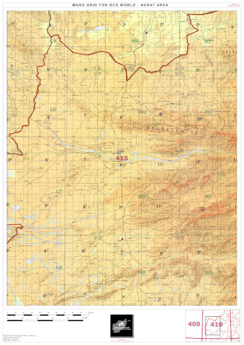
Direct download of the TPC map for Herat area is now possible in user's files: https://www.digitalcombatsimulator.com/en/files/3341084/ All the 1:500.000 TPC maps covering most of south-west Afghanistan are available on my personal page. Please let me know if you have any comments about the readability of the MGRS overlay. I can also create maps for specific areas on request, to support mission designers for example. Don't hesitate to discuss it directly with me if interested!
-
Direct download of the ONC map is now possible in user's files: https://www.digitalcombatsimulator.com/en/files/3340991/
-
Yes but using F10 map in flight is definitely cheating
-
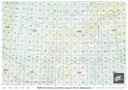
MGRS Coverage for Afghanistan and Overview Map Forenote: do you understand the differences between the various Military Coordinate Reference Systems (MGRS, CGRS, GARS, and more...)? If not, jump here :) For those interested, here are the Grid Zones for MGRS coordinates on the Afghan theater. Those who'd like to navigate more in details the MGRS grid for Afghanistan can visit https://mappingsupport.com. You can also download a high resolution 1:1.000.000 map here. Eventually, I also published 1:500.000 maps (more areas to come soon). Now you can enjoy hassle-free re-taskings anytime and anywhere!
-
We definitely need Afghan trucks...
-
Tactical landings often imply high angle of descent procedures (video here), and are fairly difficult to execute properly and are prone to accidents for several reasons: air density in Kandahar is reduced compared to standard conditions, resulting in lower aerodynamic performances: the average temperatures in Afghanistan are higher than in most Western countries; Kandahar's altitude is around 3000 ft: it's more than twice the altitude of the highest airport in UK for example; aircraft are often heavier than usual, due to unexpanded ordnance and additional fuel kept for diversion; engine RPM is usually low due to high angle of descent (and on purpose in order to reduce infrared signature), resulting into a longer response time in case there's a need to add extra power; the lack of training on unusual angle of descent makes it more difficult for pilots to detect abnormal conditions, and make them react later than they would on a normal landing; the pilot is aiming at the very beginning of the runway in order to benefit from the longest possible landing distance, in order to ensure that it will be possible to stop a heavy aircraft before runway end. For all these reasons, there have been a number of incidents involving fast jets landing in Kandahar, the most famous of which was undoubtedly the crash of the RAF Harrier on May 14, 2009. Fortunately, despite the total loss of the aircraft, the pilot, Martin Pert, was uninjured and went on to become the leader of the Red Arrows. The account of his ejection is particularly interesting, not least because it describes the tactical landing procedure that has been discussed here. It is also noteworthy that the pilot does not minimize the errors that led to this accident, contrary to what often happens in such circumstances...
-
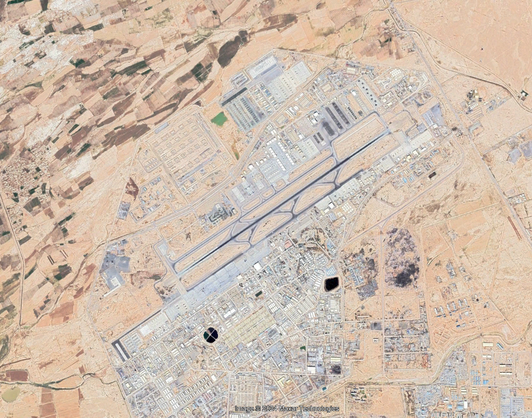
Hello, On your very first post here, you say: But if we look at the current state of the airports, we understand that the map in its current state is more representing the 2015-2021 era. Biggest clue: the state of Kandahar airport, with all the aprons on the northern part of the runway. This is the airport picture as of 2008-2010: During this period, taxiway "Gulf" was not even a thing, and you could only taxi to runway 05 via taxiway "Foxtrot" (the south taxiway). We have to wait until 2011 to see all the new aprons on the north of the runway: Another hint: the building of Nimroz Airport (OANZ) started in late 2011. In the 2008-2010 period, Zaranj Airport (OAZJ) in the center of the city was the only existing runway in the vicinity. We have to wait until 2013 to see the works on the runway. Before that, it was just an empty stretch of sand... So my question is: do you still intend to represent the 2008-2010 period? And if so, will such anachronisms be corrected in the future? Thank you,
-
Tactical or standard procedures? As you might have noticed already, the civilian departure and landing charts don't give a lot of information regarding military procedures, especially in the very particular context of counterinsurgency. Indeed, counter-insurgency (or COIN) operations such as those in Afghanistan present very special characteristics for fighter aircraft: the departure and/or recovery airfield is located in a hostile environment. While this may be the norm for helicopters and tactical transport pilots, it is very rarely the case for fighters and strategic transport aircraft, which generally have sufficient range and autonomy to operate from a relatively safe location. But operating either from Middle East or from former Soviet Republics was very costly in terms of resources: many hours were spent in transit, therefore consuming costly hours of flight without operational value. For the case of Kandahar, if the airfield was used by the US forces since the very first weeks of the war in 2001, we have to wait until 2004 to see the first British Tornado, 2006 to see the first Dutch F-16, and 2008 to see the first French Mirage 2000D or Belgian F-16. Deciding which type of operations to carry out (tactical or standard) requires a balanced decision in terms of risk management: what's more likely to happen? am I more likely to be shot down by an insurgent preparing an ambush near the airport? or am I more likely to collide with another aircraft on arrival or departure? If the first risk predominates, tactical operations should be chosen. If this is not the case, standard procedures should be followed, which have long been tried and tested and are known to all parties. Estimated risk balance between SAM threat and traffic hazard for Kandahar airport. I'll propose a dedicated study of the SAM threat around Kandahar in a dedicated topic, but we can say that with the increased number of troops deployed along time in and around Kandahar airfield, as well as the deployment of dedicated security and surveillance tools (like CCTVs or C-RAM radars), the SAM threat has steadily decreased to reach a minimum during the "surge" in 2011-2012, and has started to increase when NATO countries started to disengage after 2014-2015. In the mean time, if we have a look at the airport's activity, it has steadily increased until 2015, with Kandahar becoming the main hub or "APOD" (Aerial Port of Debarkation) for all operations in Southern Afghanistan. In September 2009, an article said that "with the increase in forces in southern Afghanistan, Kandahar Airfield has become the busiest single-runway airport in the world. Peaking in late May at an estimated 5,500 flights per week, the airfield has maintained more than 5,000 flights per week through June and July, said Col. Bill Buckey, the airfield’s operations officer, a Marine augmented to NATO’s International Security Assistance Force. Previously, the busiest single-runway airport in the world was the London Gatwick Airport, averaging around 5,000 flights per week." But the difficulty was that not only that the airport was busy in terms of movements, but it was also the wide differences in performance between the different users: the single runway was used for helicopters, tactical transport aircraft, strategic transport aircraft, UAVs and fighter jets, not to mention the civil airlines that also operated there... All in all, we can consider than during the 2009-2017 era, very standard procedures were the most appropriate: for example overhead break arrivals for fighter jets, and 3° slope straight in approaches for other aircraft. On the contrary, before 2008 and after 2018, tactical procedures would be more appropriate, like high angle final descent. For example, you have here a tactical take-off and tactical landing for a mighty C-17. For those who are interested, I have detailed on my personal page tactical take-off and landing procedures in Kandahar for fighter aircraft.
-
Bomb Fuzes options in the rearming panel
graveyard4DCS replied to graveyard4DCS's topic in General Tutorials
Application to the Case of the F/A-18C in DCS World 5.1 - FMU-139: Description The FMU-139 (series) electronic bomb fuze is an electronic impact or impact-delay fuze. It is used in Mk 80 series general-purpose bombs, including laser-guided bombs. The arming times can be in-flight selectable, and the functioning delay must be set during weapon assembly. Theoretical use The U.S. Navy’s F/A-18 fuzing system can be divided into two major subsystems, which are the aircraft and the weapon. The FA-18 aircraft subsystems that affect weapon release and reliability include: aircraft software, AWW-4 Fuze Function Control Set (FFCS), aircraft wiring, connections, decoders, and bomb racks. The weapon subsystems include: a MK-122 safety arming switch with M70 bomb cable assembly or a FZU-48 bomb fuze initiator with a coil power cable, a FMU-139 electro-mechanical fuze, a bomb tail section, and MK-3 arming wire. The fuzing system is identical when used in “dumb” free-fall bombs and “smart” LGBs or JDAMs because they are all based on legacy MK-80 series bomb bodies. The FMU-139 does not contain its own internal source of electrical power but relies on an externally produced supply of direct current (DC) provided by either the aircraft at release or a ram-air turbine generator mounted in the warhead’s charging well. The fuze will function differently depending on the electrical power provided. The current U.S. Navy FMU-139 electro-mechanical bomb fuze within the bomb fuzing system receives power from either the aircraft Fuze Function and Control Set (FFCS) by a pulse through the MK-122 arming switch and M70 cable assembly or continuously from a FZU-48 air turbine. The fuze does not receive power until the bomb is separated from the aircraft for both bomb fuzing configurations. Only Navy aircraft have an FFCS and so this mode is sometimes referred to as “Navy mode.” The Air Force were first to utilize the air turbine to power their fuzes and not until 2001 have Navy aircraft used the air turbine mode so this mode is sometimes referred to as “Air Force mode.” When looking more closely at the FMU-139’s faceplate, we can notice on the upper part the “LOW DRAG ARM TIME” settings. In order to use the “Navy mod”, the screw has to be placed on the X setting. When using the “Air Force mode”, the low drag arming delay has to be set to the desired value. In this configuration, the setup is selected on the ground, and cannot be modified in flight. The “Navy mode” brings an extra flexibility, because the arming delay can be selected in-flight, while it’s locked on a single value in “Air Force mode”. In “Navy mode”, the crew must select two different settings: the arming time (ARM: either 5.5S or 10S) and the explosion delay (EFUZ: OFF, INST or DLY1). Once this is done, the plane’s FFCS will send a specific electrical current to the bomb that will understand the required configuration. In “Air Force mode”, the EFUZ setting is replaced by an MFUZ setting, that will only let the pilot decide whether the bomb will be armed (TAIL) or not (OFF). Selecting the ARM setting to either 6”, 7”, 10”, 14” or 20” has no effect on the actual arming delay, since it has been set up on the ground, but it will enable correct DUD cues on the HUD (when trying to drop the bombs too low for example). Regarding the explosion delay, it is set up on the ground by the screw on the lower part of the faceplate. Four values are selectable: INST, 10 ms, 25 ms or 60 ms. As described above, these settings cannot be modified anymore in flight, unless in “Navy mode” where it’s possible to force an INST setting even if a longer delay has been selected on the faceplate. As indicated on the FMU-139’s faceplate, the same fuze can be used for high drag bombs. The fuze has a built-in accelerometer, and if after bomb release a strong deceleration is sensed, the HIGH DRAG settings will be automatically applied. If this event is not detected, the LOW DRAG settings apply. We can notice that in HIGH DRAG configuration, four arming delays are selectable: 2.0”, 2.6”, 4” and 5”. The 2.0” option is marked in red and requires a manual push on the “interlock” button to confirm that the selection is intentional. But it has to be understood that this delay is very short and poses great risks for the shooter, and its use is actually forbidden. You’ll find below a flow chart summarizing all the possible configurations for the FMU-139. Current situation in DCS World: Current DCS fuzing options do not offer the possibility to use the X setting on the FMU-139. It means that the FMU-139 is always used in “Air Force mode”, and that only the MFUZ option should appear in the STORE pages, both with dumb bombs, LGBs and JDAMs. In reality, the current model does is not following this logic, and the options on the STORE page are always the same, whatever the actual fuze choice: Mk-8X - Low Drag & High Drag MFUZ/OFF-NOSE-TAIL-N/T or MFUZ/OFF-NOSE or MFUZ/OFF-TAIL or EFUZ / OFF-INST-DLY1-DLY2 or a combination of both EFUZ and MFUZ when selecting a mechanical fuze and an electronic fuze on the same body (a situation that never happens). GBU-1x / 2x - General purpose: EFUZ / OFF-INST-DLY1-DLY2 JDAM - General purpose: EFUZ / OFF-(VT1)-INST Note: for cluster bombs, the settings are: MFUZ/OFF-PRI-OPT (Mk 339 - PRI = PRIMARY = first time setting, OPT = OPTION = second time setting.) or MFUZ/OFF-VT1-VT2 (FMU-140). Therefore, as of 2024, it is clear that the parameters in the STORE pages in DCS World are not correct. They tend to mix several concepts, and do not take into account the programmable side of some fuzes. For example, the correct stores format options for JDAM are described in the table below. This is what the developers should try to reproduce to go to the end of their development process. Read the original article for more details about FMU-143, FMU-152, DSU-33, M904, M905, Mk 339 Mod 1 and FMU-140. A kneeboard page summarizing recommended fuze settings for the F/A-18C in DCS World is also available. -
For those who'd like to find departure and landing charts for other airfields in SW Afghanistan, I published an article explaining how to find them for various eras: How to Find Airport Charts for Afghanistan? null Timeline of websites publishing AIPs for Afghanistan. I'll release other sets of charts for SW Afghanistan in the coming weeks.
-
1:500.000 Tactical Pilotage Charts for CombatFlite The logical follow-up to the previous ONC 1:1.000.000 was, of course, the publication of a set of smaller-scale aeronautical charts. In general, 1:1.000.000 scale charts are used for long-distance, high-altitude flights, to give an overview of the route and to easily find diversion airfields. But they are not detailed enough to plan and execute visual navigation. For this purpose, 1:500.000 scale maps are generally used: at this scale, it is possible to see details such as villages, bridges, forests and antennas - the kind of visual features that are useful for low-level flying. The only 1:500.000 maps available for Afghanistan in the early 2000s were the old US TPC maps, the very same that have been chosen here. As for the ONC maps, I decided to include large areas around Afghanistan, up to Kyrgyzstan to the North. More maps for even lower scales will be released in the future.
-
I've put together a set of charts for Kandahar airport, along with some useful additional information. These charts are the official instrument procedures issued by the US DOD FLIP, but published on the internet for use by all crews landing at Kandahar. They can be downloaded by all members from my personal page. As you will soon discover, all the information dates from 2008-2010, and the northern aprons do not correspond to the airfield as represented in the game. Therefore, I'll soon be publishing another version for the 2017-2019 era. I will also take the time to guide you on how and where to find this type of data. List of charts. Example of departure chart. Example of landing chart.
-
Bomb Fuzes options in the rearming panel
graveyard4DCS replied to graveyard4DCS's topic in General Tutorials
I eventually started writing a guide on this topic. You'll find the first part here. All other parts are on my personal page, don't hesitate to check it. Bombs fuzes - Introduction In 2024, the release of the fuzes options in the rearming panel in DCS World brought a new level of realism and complexity to this very unique flight simulator. Understanding what’s the role of a fuze, how it works and what the different settings are, is necessary in order to use this feature correctly, i.e. to maximize damages to the target and avoid duds or self-damages. This article is a short introduction to the essentials terms that have to be known and to what an " aerial bomb" is comprised of. 1.1 - References Articles: Understanding the FMU-139 and Its Employment Options; Documents: NAVAIR 11-1F-2 - Description and Characteristics - Airborne Bomb and Rocket Fuze Manual; Safe arming times for Mk-81, Mk-82, Mk-83, Mk-84 and M117 Low Drag Bombs; Increasing the Reliability of General Purpose Bomb Fuzing in Precision Strike Warfare; Explosive Weapons Effects by GICHD; USAF JDAM Tactical Manual on Wikileaks; 1.2 - 1.3Definitions Fuse: cord or tube for the transmission of flame or explosion usually consisting of cord or rope with gunpowder or high explosive spun into it. Fuze: a physical system designed to respond to one or more prescribed conditions, such as elapsed time, pressure, or command, and initiate a train of fire or detonation in a munition. Safety and arming are primary roles performed by a fuze to preclude ignition of the munition before the desired position or time. The spelling FUZE is used to denote a sophisticated ignition device incorporating mechanical and/or electronic components for example a proximity fuze for an artillery shell, magnetic/acoustic fuze on a sea mine, spring-loaded grenade fuze, pencil detonator or anti-handling device as opposed to a simple “burning fuse”. Main charge: the explosive charge which is provided to accomplish the end result in the munition; e.g., bursting a casing to produce blast and fragmentation. These explosives, because of their relative insensitivity, ordinarily require initiation by a booster explosive. Armed: a fuze is considered armed when any firing stimulus can produce fuze function. Function: a fuze “functions” when it produces an output capable of initiating a train of fire or detonation in an associated munition. Arming delay or arm time: the time elapsed from launch to arming. Dud: a munition which has failed to function, although functioning was intended. Early burst: a weapon detonating after completion of the arming delay but before hitting the intended target. Premature function: a fuze function before completion of the arming delay. Safe separation distance: the minimum distance between the delivery system (or launcher) and the launched munition beyond which the hazards to the delivery system and its personnel resulting from the functioning of the munition are acceptable. Safety and arming device: a device that prevents fuze arming until an acceptable set of conditions has been achieved and subsequently effects arming and allows functioning. Explosive train: the detonation or deflagration train (i.e., transfer mechanism), beginning with the first explosive element (e.g., primer, detonator) and terminating in the main charge (e.g., munition functional mechanism, high explosive, pyrotechnic compound). 1.3 - Bomb description Bomb bodies are made up of multiple parts. We can distinguish in particular: the nose plug (1): it has a role in terms of mid-course ballistics and target penetration. In particular, the MXU-735 is a round shaped solid nose plug that is designed to provide better penetration of hard targets, without the likelihood of nose plug shearing during oblique impact. the arming wire(s) (13): they are a physical link between the aircraft’s pylon and the bomb. When the bomb falls away from the aircraft, the wires that have been selected in the cockpit (nose, tail or both) are pulled away from the parts to which they have been linked to on the bomb (e.g. the nose fuze, or the battery for a PWY-II), thus authorizing the functioning of the mechanism. If the arming wire has not been selected, the bomb is dropped with its wire still attached and the associated mechanism won’t function. For example, during a jettison, the bombs are dropped with their wire and are therefore inert. Physically speaking, the wires can in some cases be “crossed” on the bomb’s body, meaning that selecting the “nose” option in the cockpit will actually enable the “tail” fuze on the bomb. In any case, the crew has to know the effects of the cockpit settings, rather than the actual wiring diagrams on the bombs. the inner tubes (23): they are used to link the fuzes with the aircraft in FFCS (or “Navy”) mode (detailed later). the coating: navy bombs have a gray thermal protective coating that makes them IM or “Insensitive Munitions”, for safety on board of ships (in case of fire for example). Training munitions are painted blue. Munitions containing live explosive have a yellow stripe. fuzes (11 + 26): they will be detailed below. As you can already see, the fuzes are just a one element among many others of an aerial bomb. They will be detailed in the following articles. -
Updated: Airport and NAVAIDS database for CombatFlite As discussed earlier regarding that particular database, I wasn't quite happy with the initial data choice. I decided to dig a little into DCS theater files to see what's available there... First of all, Afghan theater files are located in the DCSWorld(OpenBeta)\Mods\terrains\Afghanistan folder. If most files are ciphered, some .lua files are readable and give us almost all the desired information. Let's start with the beacon.lua file: it describes all the active beacons on the theater. We can see that each airfield has a number that corresponds to the DCSID field in the CombatFlite database. We can also note that frequencies are indicated in Hz, since 2 letters beacons are generally NDBs that work in the kHz frequency range. The location is given directly in DD.DD, that is to say the correct format for our CombatFlite database. We can therefore say that this file contains all the information needed to reproduce actual DCS NAVAIDs in CombatFlite! The various beacon types for this theater are: HOMER (or NDB), TACAN and VOR-DME. But if we look into other theaters, we can find VORTAC, ILS LOCALIZER and ILS GLIDESLOPE, but also RSBN, a Russian short-range navigation system. At this stage, the beacons list for the Afghan theater is clearly short. Let's hope it will get more comprehensive in future updates. Then we can have a closer look a the radio.lua file: it lists all the default AI frequencies on various airfields. It gives us both a list of airfields, and the list of radio frequencies, so most of the information needed to finalize our database. Once again, frequencies are given in Hz. Airfields are identified through their ICAO code most of the time, like OABT for Bost airport in the previous example. Some airfields, like Camp Bastion (OAZI) have two set of data: one set for helicopters and the other set for aircraft, which certainly means that we can have segregated helicopters and aircraft traffic on that airfield. One airfield is designated by a call-sign, "YARDBIRD", which is in fact the call-sign of Dwyer Airport (OADY). One airport is designated by "CTAF", which stands for Common Traffic Advisory Frequency. It designates a frequency used on non-controlled airfields, for advisory calls. It's not clear if an airfield is supposed to be linked to this particular entry. Last interesting information: Nimroz airport (OANZ) is included in the frequency list, even if it has not been announced among the airfields on the SW Afghanistan theater. It has been built to replace Zaranj airport (OAZJ) and in order for the theater to be coherent, either one or the other airport only should be listed. In the 2007-2011 time-frame announced by DCS, only Zaranj should be available. Eventually, we can note that the DCSWorld(OpenBeta)\Mods\terrains\Afghanistan\Map folder contains a towns.lua file that lists the name and location of all the towns and villages on the theater. It is supposed to be used by the Ka-50's ABRIS navigation system. It can be used to complete CombatFlite's town database, but since it's apparently not used in the software at this stage, I won't dig in it for the moment. All these info let us build a database that's much closer to the game's state. It is available here , and should replace your persiangulf.xlm file in your CombatFlite\Data folder. However, even if this method brings us quality data, it will also force us to check for changes after each theater's update...
-
Thanks for the feedback, it was indeed a typo in the link, the final dot had to be removed. The link has been corrected and should be working now.
-
Since the bomb fuzes are now available in DCS World, do you think it's necessary to invest time in researching information and creating a guide to their operation and use?