walmis
-
Posts
301 -
Joined
-
Last visited
-
Days Won
13
Content Type
Profiles
Forums
Events
Everything posted by walmis
-

Post MotherBoard Specs Of Bricked TM Warthogs Here Please
walmis replied to twobells's topic in Thrustmaster
There's also my fork https://github.com/walmis/arduino_hssp/commits/master based on miracoli. I've made a few changes you can see in the commit list. I didn't proceed with the the vector attack. Since resoldering the chip magically worked, I decided not to waste more time on this. But this is interesting nonetheless and hope something comes out of it. I think first ~6K of flash is the read protected bootloader. Doubt it will dump the bootloader, but worth a try. One attack I could think of would be to load an app using existing app structure (see .tmf). I did not manage to find the correct entry point jump address, btw. The rogue app would dump the data of the bootloader using ROMX instruction. It shouldn't be too difficult (I guess) to patch in a loop which would bitbang data to gpio. Sadly the PSoC1 tools are quite old. Maybe some cmdline utilities might be useful from the PSoC1 designer software. I did install that on WinXP virtual machine, LOL. BTW, I did manage to reflash the same dump using arduino_hssp and psocdude (but without erasing chip ! ) and that firmware worked after resoldering the chip. So that confirms the arduino_hssp should work (my fork). Info dump: CY8C24894 datasheet AN2100 Bootloader: PSoC® 1 Infineon-Assembler.book-UserManual-v01_00-EN.pdf PSoC® USB HID Bootloader Getting Started With PSoC® 1 https://github.com/steve-m/m8cutils https://www.mikekohn.net/micro/naken_asm.php - powerful disassembler/assembler/simulator -
Post MotherBoard Specs Of Bricked TM Warthogs Here Please
walmis replied to twobells's topic in Thrustmaster
Sadly I scrapped the idea after realizing the bootloader part is read protected. I tried various stuff like disassembling existing TM firmware, trying to compile a hello world image using the PSoC designer and comparing the vector table structure to TM firmware, trying HSSP commands. This post is interesting and a good reference https://syscall.eu/blog/2018/03/12/aigo_part2/ -
Honey, I developed FFB joystick (DIY)
walmis replied to propeler's topic in PC Hardware and Related Software
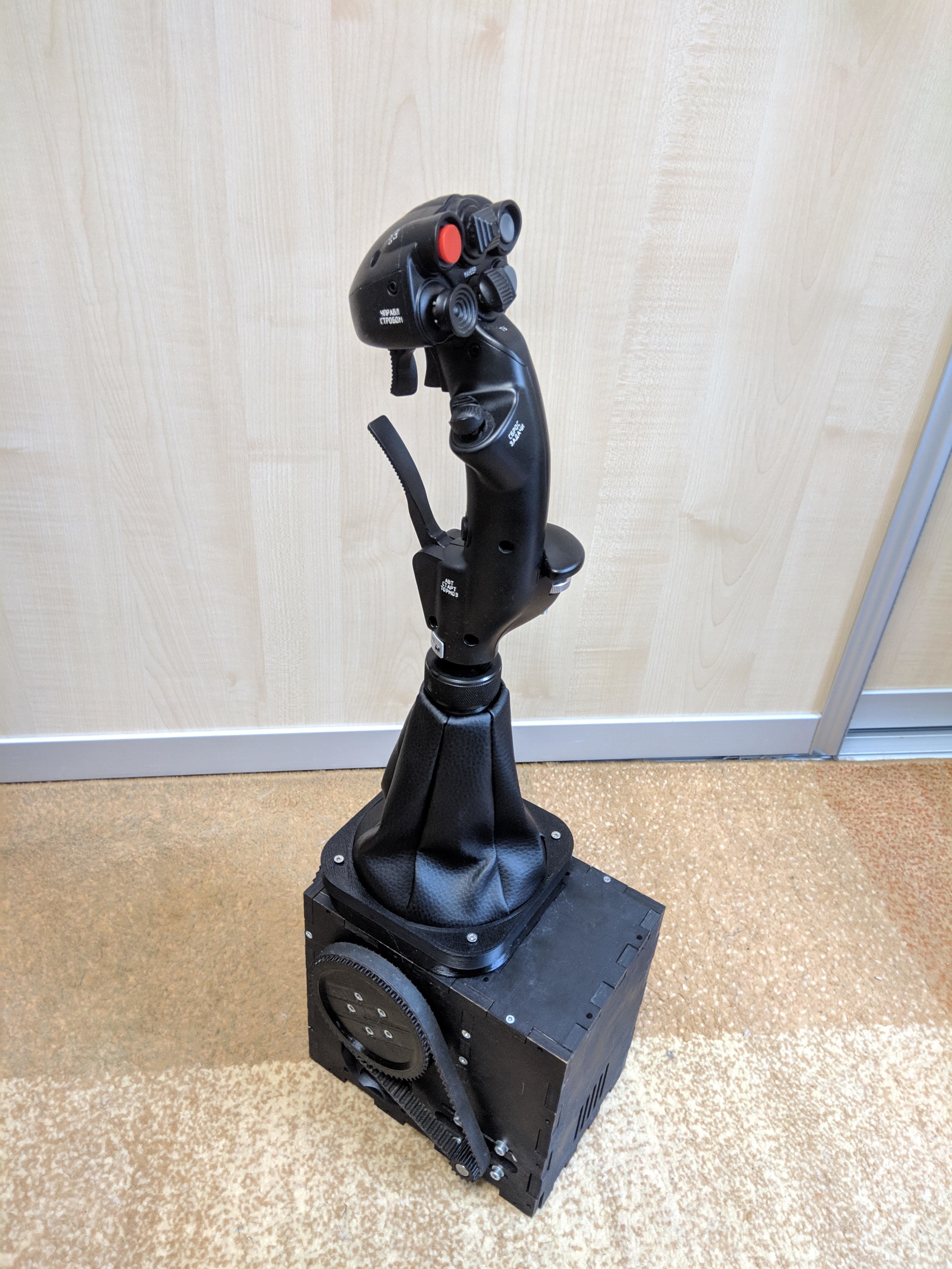
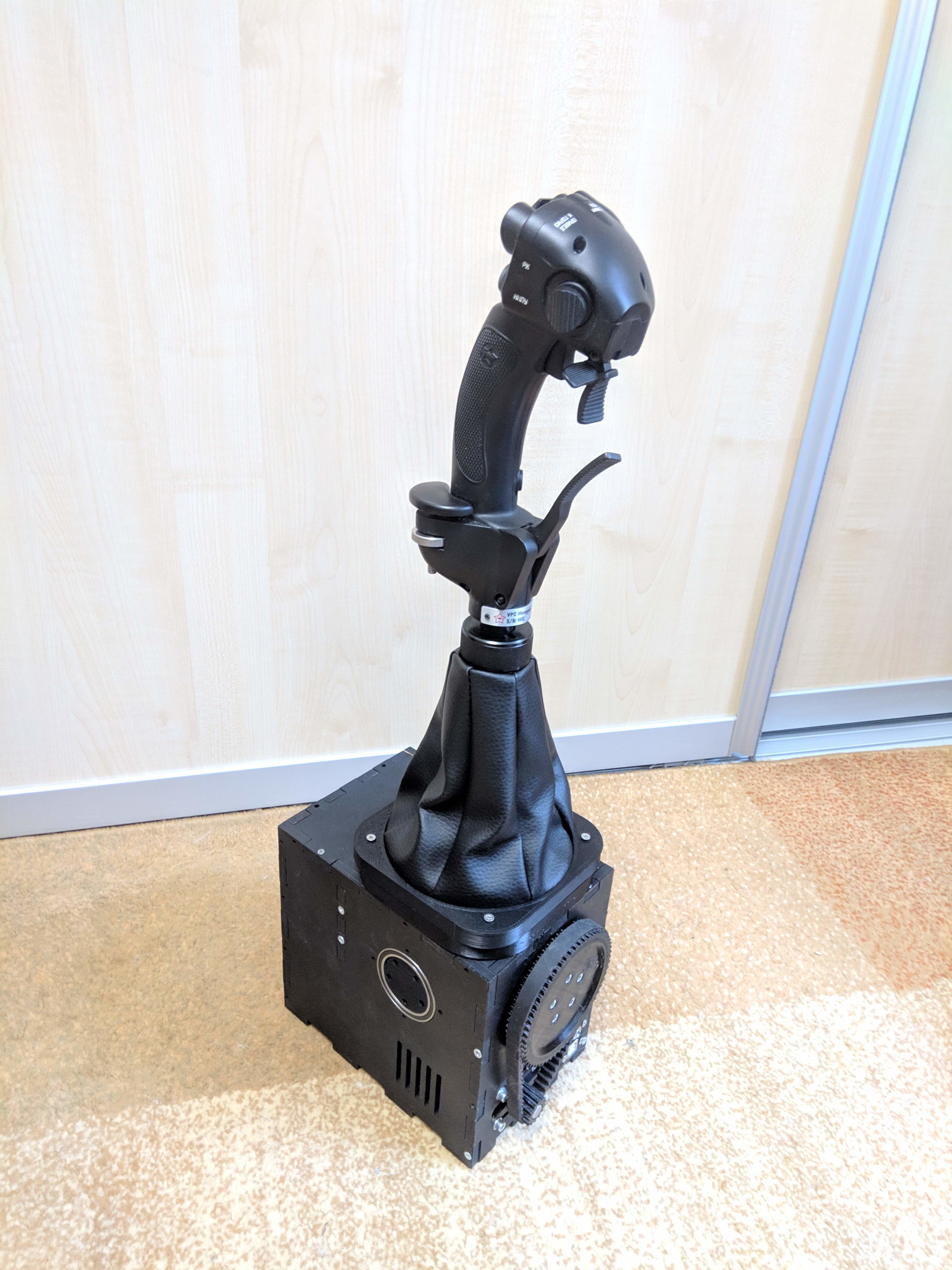
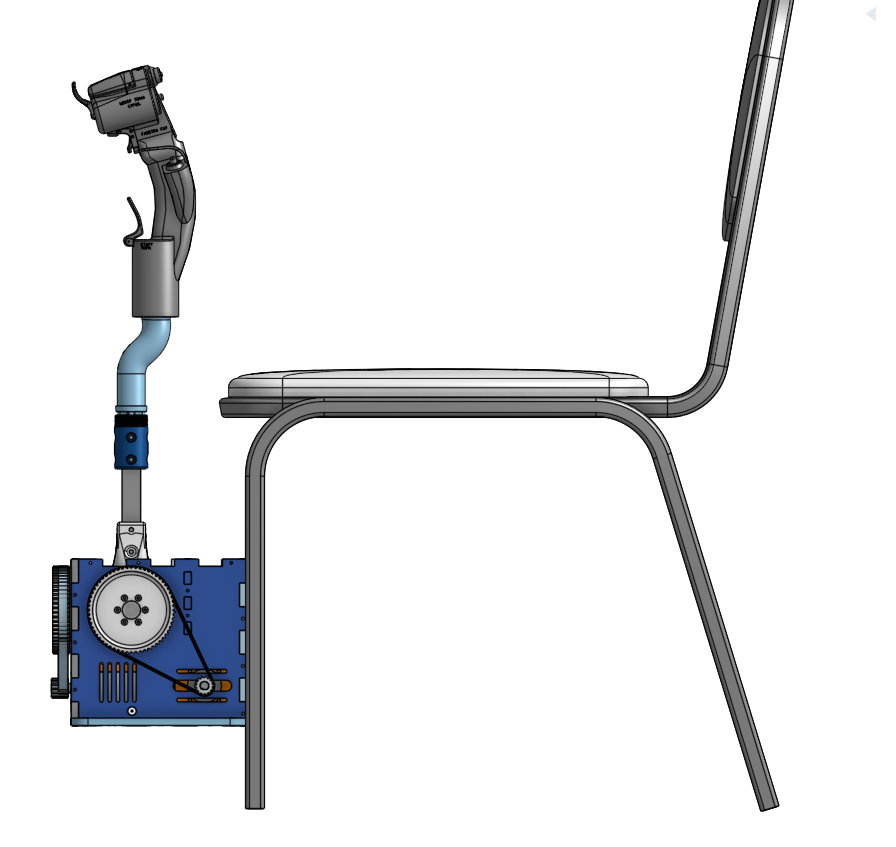
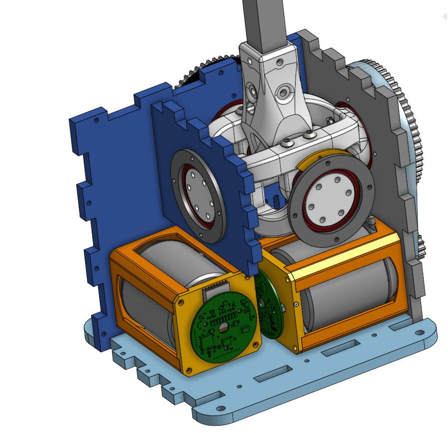
Here is my first prototype design. Dual pulley reduction, lots of torque Some parts are missing, didn't maintain this project for a while. With anticogged motors it produces very smooth operation. There are a few issues with belt slipping. I initially I used HTD3M belts, but HTD5M with better belt tensioning should solve that. I think the biggest problem with FFB with fancy motors is the huge price tag and sourcing. I did some tradeoffs and went for more ubiquitous motors.
-
Honey, I developed FFB joystick (DIY)
walmis replied to propeler's topic in PC Hardware and Related Software
Hello there, Yes but sadly the app does not use any standard communications, it interfaces directly with my FFB joystick's firmware, so no way to affect MSFFB2. -
Honey, I developed FFB joystick (DIY)
walmis replied to propeler's topic in PC Hardware and Related Software
The thing is that the "inside" holes are usually smaller than the "outside" holes. That explains why main bearings went in OK, but the smaller ones had a too tight fit. I usually add a 0.4mm tolerance for the inside holes. ABS has the worst shrinkage so makes the problem worse. PETG is best on the shrinkage aspects so parts are more dimensionally accurate. Not sure about your material. -
Honey, I developed FFB joystick (DIY)
walmis replied to propeler's topic in PC Hardware and Related Software
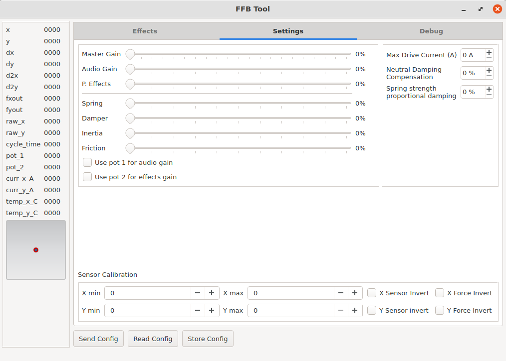
Yeah, a yoke should be possible too. The mechanics should be able to accept two NEMA23 case motors. The USB board supports standard FFB implementation. I'm also working on a support application to adjust additional settings, such as calibration, firmware update, etc.. Working on this! Supply side of things is complicated, but my guess this year I should be able to get something ready. Price target would be around 250-300$ for 2 motors with integrated electronics and a USB control board. -
Honey, I developed FFB joystick (DIY)
walmis replied to propeler's topic in PC Hardware and Related Software
Hey guys, an update on my FFB development. Ordered FFB controller boards and boards for the motor control, redesigned the gimbal from scratch, so not to be bound by copyrights. Also spent some time on optimizing the design, so it could be built rather quickly. Finding sources of parts is also a challenge during these times of various shortages. I'm hoping I will be able to start selling these electronics kits for anyone that wants to build own FFB joysticks. And later some finished builds, similarily how Prusa started with 3D printers Added some prototype photos
-
Post MotherBoard Specs Of Bricked TM Warthogs Here Please
walmis replied to twobells's topic in Thrustmaster
The original soldering looked fine, therefore I was surprised resoldering the chip actually worked. Maybe heat corrected some fault inside the chip, similar how old GPUs in laptops were fixed by heating them. The throttle still works fine to this day. Actually a hot air station is required to perform this procedure. Iron only does not suffice here. As for the iron, I can't recommend TS-100 enough - last iron you'll ever need https://eleshop.eu/ts100.html (also lots of options available on aliexpress, banggood etc.) This video shows how the procedure looks like: -
Honey, I developed FFB joystick (DIY)
walmis replied to propeler's topic in PC Hardware and Related Software
Yes, you will need to print a spacer. I'm using regular wood screws for the sides. I drill a small hole in the side of the plywood and screw in a small wood screw. Tabs do a pretty good job to hold this thing in place. It even holds together without any screws lol. I think wood screws would work also well for plastic. -
Honey, I developed FFB joystick (DIY)
walmis replied to propeler's topic in PC Hardware and Related Software
Hi, I've added the box assembly step file https://github.com/walmis/FFB-Joystick-Base/tree/master/CAD -
Honey, I developed FFB joystick (DIY)
walmis replied to propeler's topic in PC Hardware and Related Software
What about water jet? I attached ffb case laser cut production files I used for the prototype, I used locally sourced 380 × 500 mm x 8 mm plywood sheets. I'll arrange 3d printable stl's later to a github repo probably. Oh, and belts are 375mm 5M and 475mm 5M ffb-case-8mm_laser_1.pdf ffb-case-8mm_laser_2.pdf -
Honey, I developed FFB joystick (DIY)
walmis replied to propeler's topic in PC Hardware and Related Software
Well, I definitely don't plan to use your work for commercial purposes -
Honey, I developed FFB joystick (DIY)
walmis replied to propeler's topic in PC Hardware and Related Software
Yes, that's my goal I'd like to make this my full time operation, but currently I only develop/build during my spare time. Who knows, maybe this will grow into something bigger. Gotta quit my day job first LOL. Btw, what flaws does the Brunner have? -
Honey, I developed FFB joystick (DIY)
walmis replied to propeler's topic in PC Hardware and Related Software
Hey guys, another force test: This time with propellers' gimbal variant. To be honest I'm surprised it managed to pull this much with single reduction gear. 6374 170KV motors, Wye windings ~23 phase amps (Q current in FOC terms) into the motor shown above at maximum. -
Honey, I developed FFB joystick (DIY)
walmis replied to propeler's topic in PC Hardware and Related Software
Yep, working towards that. Yes, actually I'm building another (more simplified) FFB joystick base based on propellers' gimbal. Those force numbers were with my other FFB base, that one is based on 57BLF03 which for the price provides quite nice torque. For the ~50EUR motors, I think these are the winner for FFB. Also that FFB base has more reduction gearing, so that adds more torque to the stick. For propellers variant i used these motors, reterminated with Wye termination. Gonna test torque output later From my understanding delta winding is more simple to manufacture, hence lower price and most hobby motors need more RPM, so that's a bonus. Power output is the same for both windings, just the torque/RPM characteristic is different. Our FFB application is different, because we operate in the zero RPM/max torque area, which means lower Kv the better. Also there is another tradeoff - high Kv motor - more current for same torque, more power is dissipated in MOSFETs. Low Kv motor - less current for same torque - more power is dissipated in the motor windings because of higher winding resistance. -
Honey, I developed FFB joystick (DIY)
walmis replied to propeler's topic in PC Hardware and Related Software
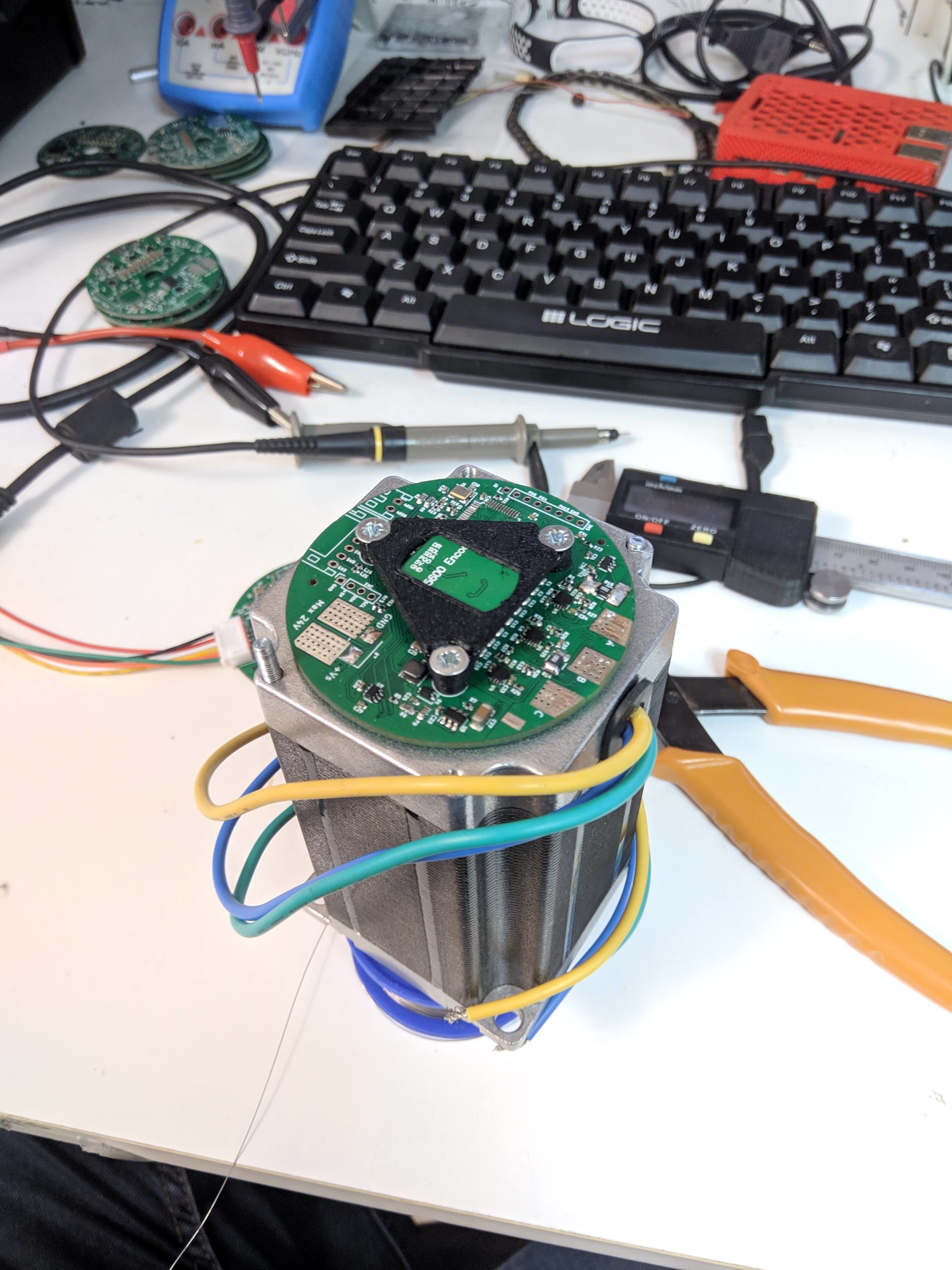
Hey guys, a little demonstration on how the anticogging works on my motor drivers: I also made an interesting finding - most hobby grade motors are wound using the the Delta winding termination, I reterminated my motors using the Wye(star) pattern, and gained 1.7x more torque per Amp for free So essentialy a 170Kv motor is now 98Kv motor using Wye termination.
-
Post MotherBoard Specs Of Bricked TM Warthogs Here Please
walmis replied to twobells's topic in Thrustmaster
I have an update. I resoldered the Cypress chip with hot air with new solder and flux and the throttle magically sprung back to life. Very weird... -
Post MotherBoard Specs Of Bricked TM Warthogs Here Please
walmis replied to twobells's topic in Thrustmaster
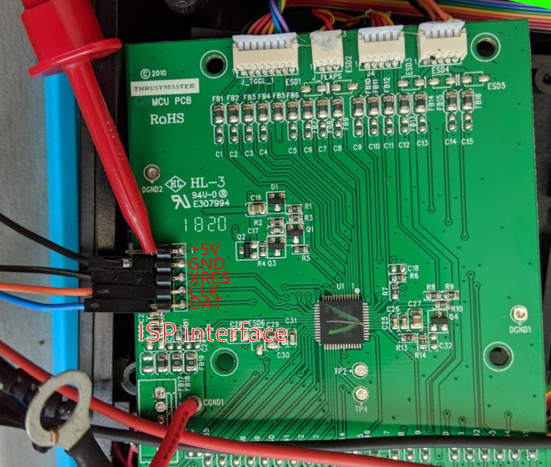
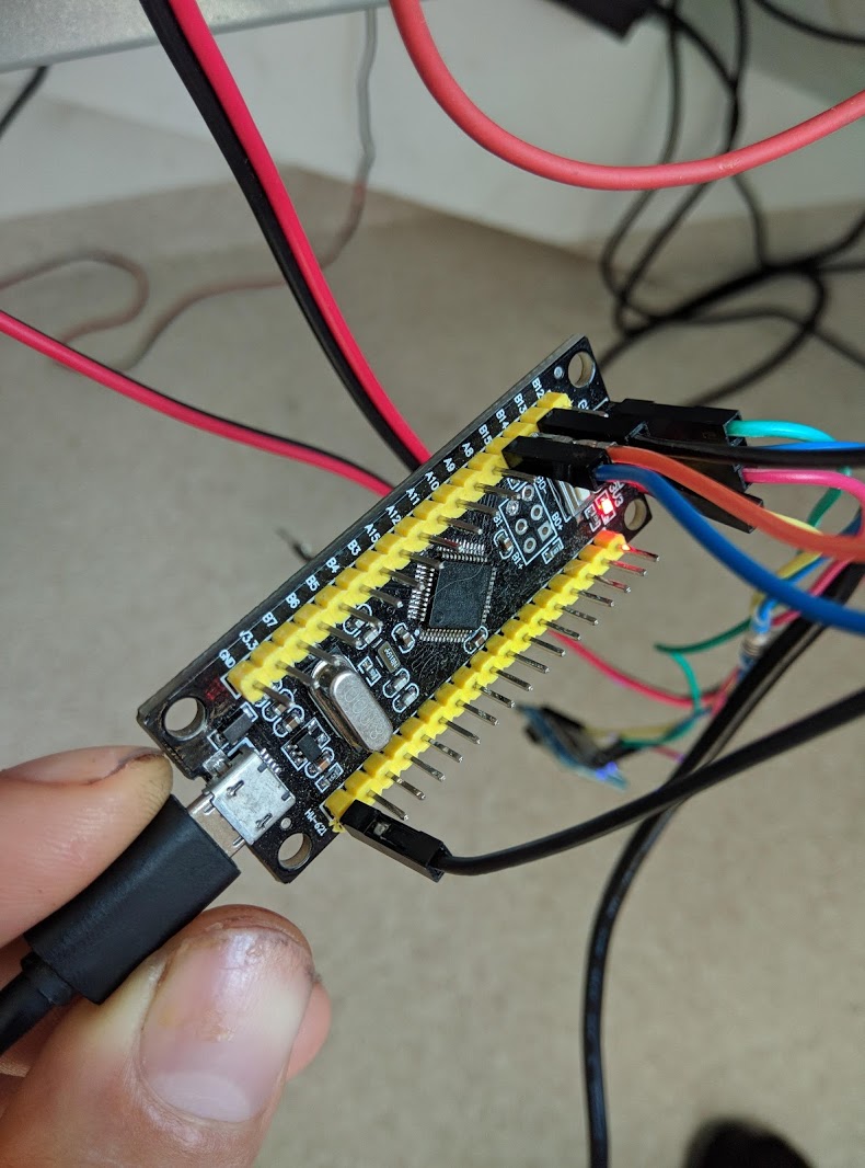
Hey guys, I have managed to dump the firmware from the PSOC chip using open source tools, sadly it is from a faulty throttle and it appears the first part of flash is corrupt. It appears the memory is not read protected, so it should be possible to dump a working image. If someone does have a bluepill STM32F103 board at hand and is willing dump firmware from a working throttle, let me know. Firmware for the STM32 programmer: https://github.com/walmis/arduino_hssp psocdude: https://github.com/walmis/psocdude Also some useful hacking tools: https://github.com/trou/cypress_psoc_tools Once you have the firmware running on the bluepill, avrdude port called psocdude can be used to dump and write firmware on the PSOC. Ubuntu machine (or VM) is recommended to easily build the required tools. dumped flash file: warthog_throttle_dump.bin For comparison firmware file dumped from the TH windows utility: HA10T_PSOC_USB_v23.tmf The ISP header is conveniently placed on the PCB. Pinout on the BluePill board: SDATA_PIN -> PB15 SCLK_PIN -> PB14 XRES_PIN -> PB13 Flash read command (ubuntu): $ ./psocdude -C psocdude.conf -p CY8C24894 -c arduino -P /dev/ttyACM0 -b 115200 -U flash:r:out.bin:r psocdude: AVR device initialized and ready to accept instructions Reading | ################################################## | 100% 0.00s psocdude: Device signature = 0x001f psocdude: reading flash memory: Reading | ################################################## | 100% 3.09s psocdude: writing output file "out.bin" psocdude done. Thank you. Flash security configuration on chip:
-
Honey, I developed FFB joystick (DIY)
walmis replied to propeler's topic in PC Hardware and Related Software
I did start from scratch, actually. Hardware part is 100% my own. Firmware is also built from scratch, I only borrowed some ideas / math from projects such as ODrive and vesc For high workloads, I think, some forced air cooling might be necessary. Currently motors are not attached so that they be able to dissipate heat into the case. I kinda ordered 10mm width by default, should be more than enough Definitely open source when it becomes available I have also a FFB USB firmware in the works for the STM32F103C8 based on libopencm3 library. @propeler also has one in the works. Stay tuned. -
Honey, I developed FFB joystick (DIY)
walmis replied to propeler's topic in PC Hardware and Related Software
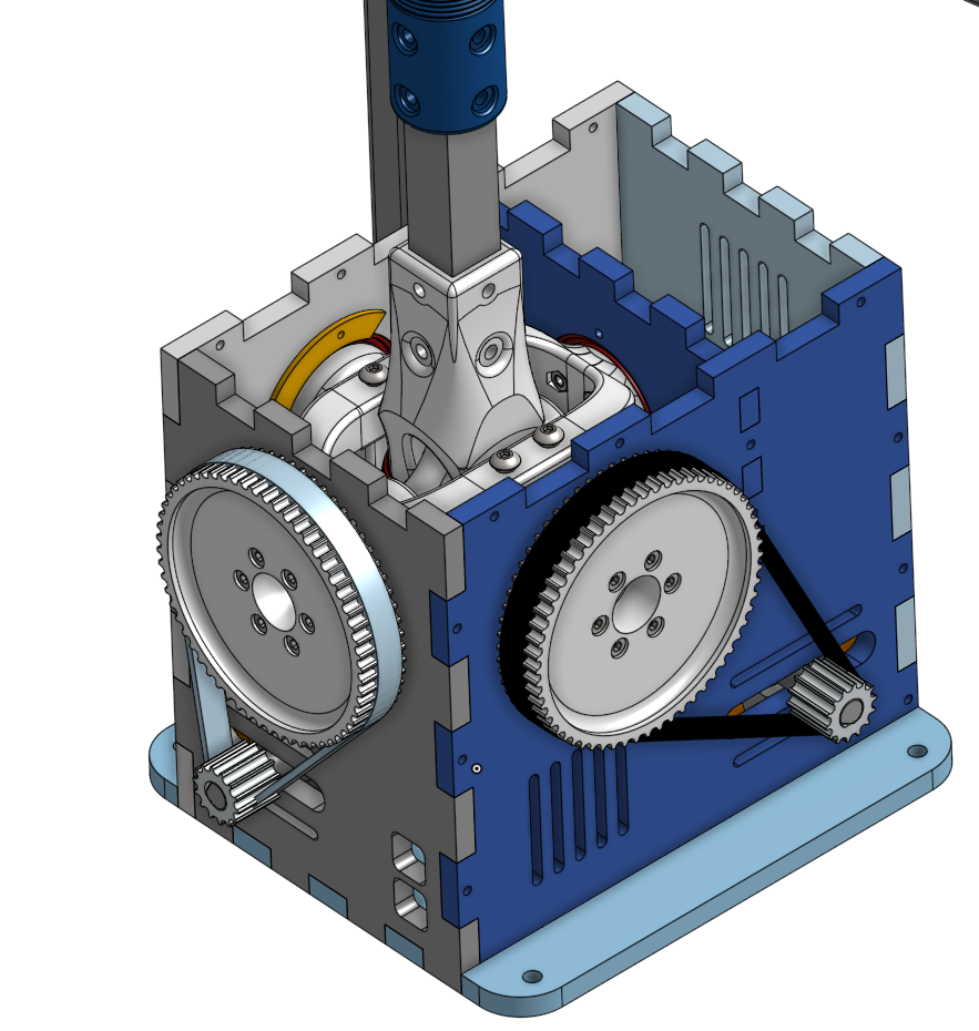
I'm planning to, I just need to finalize it further, but the firmware is in workable condition. Work on this project is a bit slow at the moment. But it'll get there I'm also building propeler's gimbal version, I just made a laser cut 8mm plywood box variant, which worked reasonable well and it's cheap. It cost me around 30Eur for cutting and materials. I incorporated 6374 size motors with my FOC controller. https://www.banggood.com/18-29V-170KV-2900kw-Electric-Skateboard-Longboard-High-Efficience-Brushless-DC-Motor-p-1240567.html?cur_warehouse=CN&rmmds=search Here are some assembly photos: I'll make sure to make some photos of the real thing, when I get back to the lab.
-
Honey, I developed FFB joystick (DIY)
walmis replied to propeler's topic in PC Hardware and Related Software
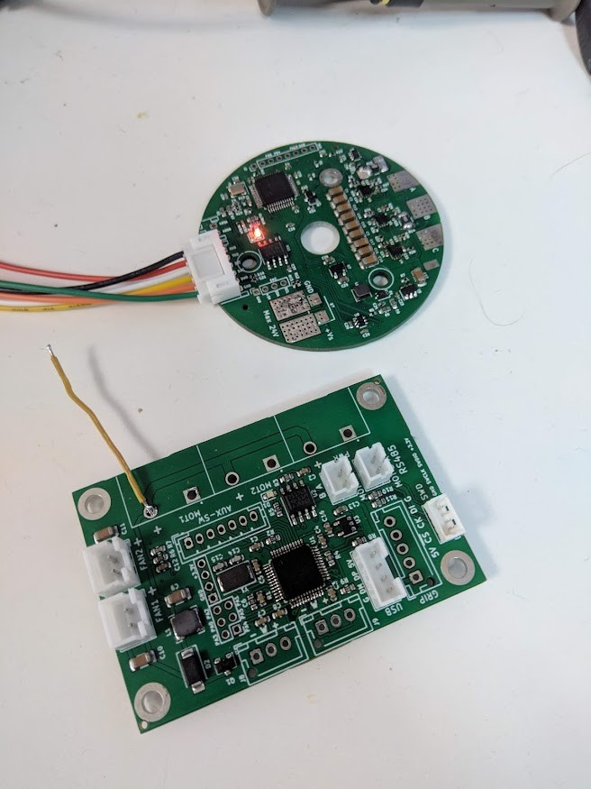
There are actually 3 controllers, 1 is the "master" which talks to the motor controllers, does USB stuff and does the effect calculations and so on. Yeah, I'm planning to put the firmware and project also on github eventually, I'm just want to "mature" it a bit, so everything works correctly. -
Honey, I developed FFB joystick (DIY)
walmis replied to propeler's topic in PC Hardware and Related Software
Did a force test on my machine. Currently I get ~5kg @ 18-20A motor current, motor dissipates around 60 Watts at that current. (Motor phase resistance is around 0.135ohm) -
Honey, I developed FFB joystick (DIY)
walmis replied to propeler's topic in PC Hardware and Related Software
It looks a bit disbalanced because of the upper motor weight, one axis would probably need a constant motor torque added to counter balance it. -
Honey, I developed FFB joystick (DIY)
walmis replied to propeler's topic in PC Hardware and Related Software
Do you have any sources/data on control characteristics? I'd like to learn more about the subject -
Honey, I developed FFB joystick (DIY)
walmis replied to propeler's topic in PC Hardware and Related Software
I highly doubt this will become an issue. You don't constantly wrestle with your joystick and that case I think your arm will get tired first LOL. Most of the time you will be in the center'ish position, which will consume close to zero current.