walmis
-
Posts
301 -
Joined
-
Last visited
-
Days Won
13
Content Type
Profiles
Forums
Events
Everything posted by walmis
-
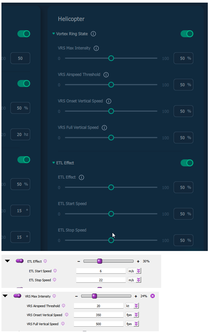
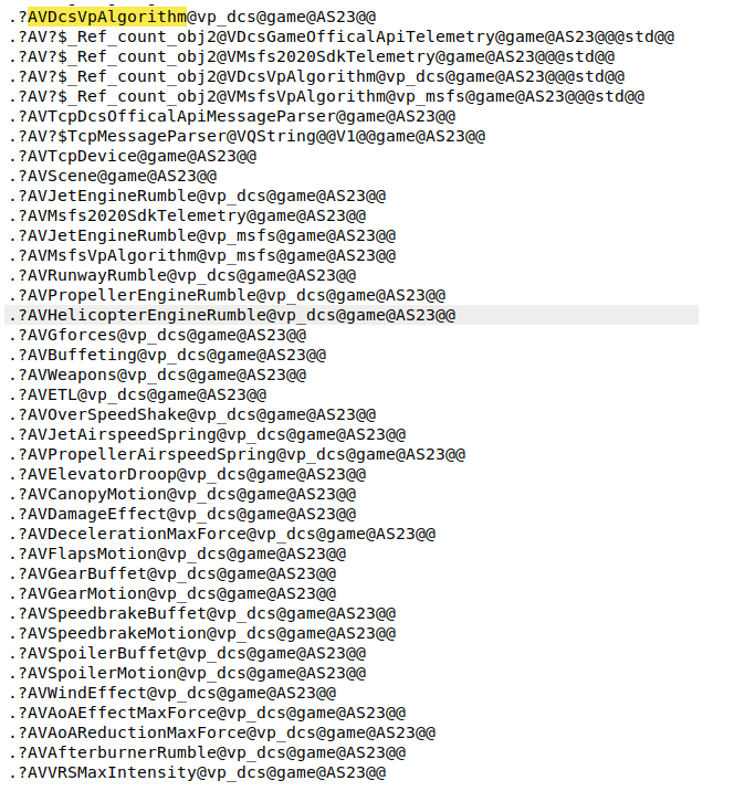
I'll provide some evidence supporting a possible GPLv3 violation. I've examined strings extracted from the Moza executable, which hint at an underlying connection to the open-source VPforce TelemFFB project. Within Moza's code, we see identifiers like vp_dcs and VpAlgorithm that incorporate the "vp" prefix, a clear nod to VPforce, though they don't exactly mirror VPforce’s original identifiers. This suggests that Moza's software may be a derivative work inspired by or partially based on TelemFFB. Given the technical leap from Python to C++, Moza likely used AI-powered tools, potentially GPT-based, to translate parts of the Python-based TelemFFB core code into C++ for their compiled binary. If Moza's code does indeed derive from TelemFFB, GPLv3 would require them to release their own source code under the same open-source license, something they haven't done. This evidence suggests that Moza may have created a derivative product based on TelemFFB without complying with GPLv3, raising concerns about a possible license violation. Next we see hastily 1:1 copied effect adjustment names They even copy pasted damage variables into their export.lua (even the line endings match!) So to summarize (thanks ChatGPT)

- 1050 replies
-
- 28
-

-

-
Worse yet is that DCS does not take account which device and which axis is bound in the controls. If there are multiple FFB devices, DCS will send X,Y axis effects and trim position to multiple FFB devices. So if you have FFB stick and pedals connected at the same time, both pedals and stick will receive the stick (x,y) trim position. Luckily we made workarounds when using TelemFFB. Additionally DCS could add more data to export.lua interface, such as actual trim position, the rest we can implement in TelemFFB app.
-

Honey, I developed FFB joystick (DIY)
walmis replied to propeler's topic in PC Hardware and Related Software
https://discord.gg/XEXZmQHk3T this one should be unlimited -
Honey, I developed FFB joystick (DIY)
walmis replied to propeler's topic in PC Hardware and Related Software
Hey, until the website is done you can join the VPforce discord: https://discord.gg/XEXZmQHk3T There's a #faq channel with the most relevant information. -
Honey, I developed FFB joystick (DIY)
walmis replied to propeler's topic in PC Hardware and Related Software
Hi, I can jump in here So a couple of advantages of the top of my head: Rhino is plug-and-play DirectInput, so no additional software is required for it to run on FFB supported games. Rhino has bigger motors and much higher gear reduction - much more torque Bigger motors with active cooling don't overheat in normal use cases. Price Here's a video showing versatility of the system in action, showing a mechanical implementation of the Rhino DIY motor kit for a custom cyclic from one of my first clients -
Hey guys, I've noticed some FFB related discussions, so I figured I'll jump in a bit since I'm working in the field for quite a while So I have been developing a a plug and play FFB system for the past few years, and recently started shipping first motor kits and first 'RHINO' FFB bases. The FFB motor kit is aimed for cockpit builders and hobby mechanics who want to build their own stick/cyclic, It solves the complicated problem of system control, motor power delivery, USB communication, etc. I very much hope more people will (re)discover FFB and we, FFB users, will receive more love from ED. Feel free to join my discord server: https://discord.gg/XEXZmQHk3T to keep in the loop about the latest developments. My YouTube channel with some FFB demos: https://www.youtube.com/user/walmis
-
Honey, I developed FFB joystick (DIY)
walmis replied to propeler's topic in PC Hardware and Related Software
Good stuff, just don't forget one important piece for such high powered equipment -
Honey, I developed FFB joystick (DIY)
walmis replied to propeler's topic in PC Hardware and Related Software
Hey guys, some quick test flights: I've also made a discord server, so most of the stuff is happening there: https://discord.gg/Y7YmFGHbee -
Honey, I developed FFB joystick (DIY)
walmis replied to propeler's topic in PC Hardware and Related Software
That type of gimbal works perfectly fine for the forces applied in this application. Of course if one wants 20kgf, you might skip the Rhino and build a DYI machine. But as a compact Brunner alternative it works perfectly fine. Disclaimer: while the gimbal might look similar to yours, I have it redesigned from scratch.
-
Honey, I developed FFB joystick (DIY)
walmis replied to propeler's topic in PC Hardware and Related Software
The servo drive can be driven up to 30-35A (the limitation is the current-sensing feedback path gets saturated with 1mOhm shunts, MOSFETS are rated up to 175A). But according to the motor datasheet, peak current is within the servo driver's current limitation. I'll need to test the real world performance. Maybe it's possible to push it more. The 57BLF03 does indeed have a D shaft: Can you elaborate more on "shaft-winding"? sounds interesting
-
Honey, I developed FFB joystick (DIY)
walmis replied to propeler's topic in PC Hardware and Related Software
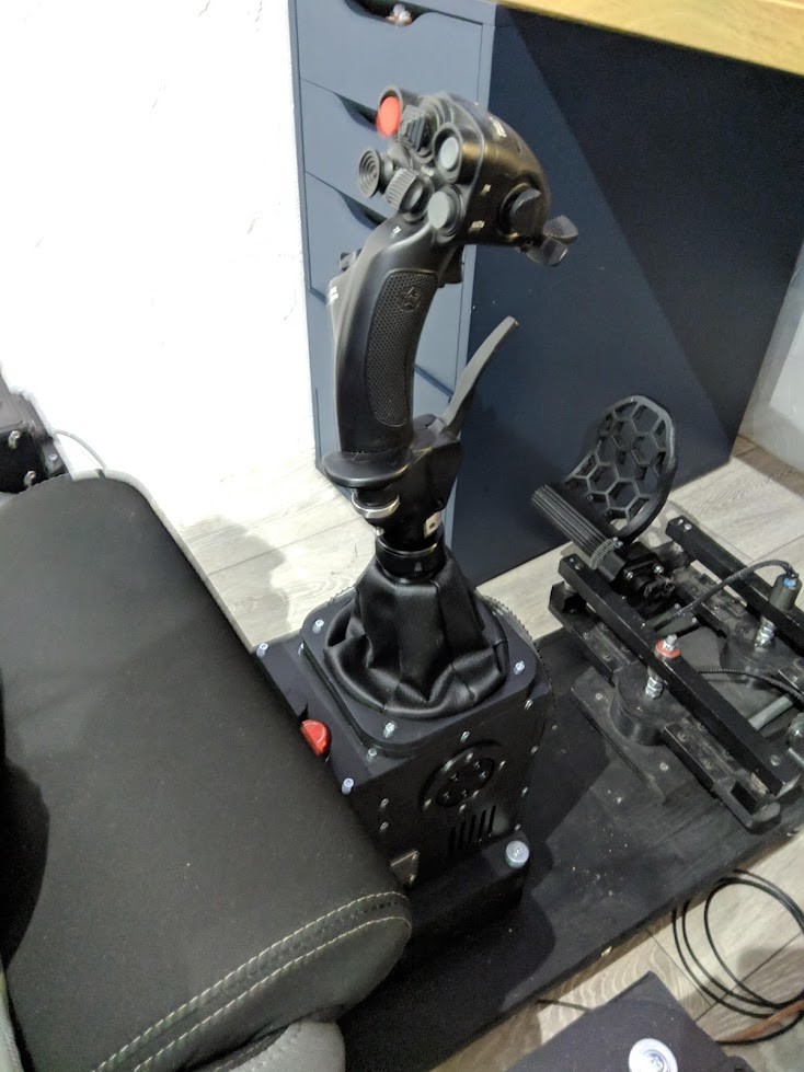
Yes, definitely! Got my hands on a few samples of 86BLF03 motors. Installed the servo drive. Works a treat. Happy to say I will be able to supply them. Demo of the big boy in action with the 57BLF03 for scale: https://gfycat.com/unrulyentirebilby -
Honey, I developed FFB joystick (DIY)
walmis replied to propeler's topic in PC Hardware and Related Software
Hey guys, I've uploaded an album featuring RHINO FFB Base. https://imgur.com/gallery/Do6Jr0T -
Honey, I developed FFB joystick (DIY)
walmis replied to propeler's topic in PC Hardware and Related Software
I have this planned. It will be easy to disable X or Y axis and adjusting the feedback parameters as desired for the single axis! -
Honey, I developed FFB joystick (DIY)
walmis replied to propeler's topic in PC Hardware and Related Software
Been researching how to improve the implementation of the Friction effect. Think I found a solution. This will be a solution to implement a Helo Collective for example without messing with complex mechanics. -
Honey, I developed FFB joystick (DIY)
walmis replied to propeler's topic in PC Hardware and Related Software
The motors are rated 3000rpm at 24V. I have used these with my first base, which has 1:24 ratio pulleys. Works just fine -
Honey, I developed FFB joystick (DIY)
walmis replied to propeler's topic in PC Hardware and Related Software
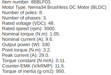
Thanks! Although I do lots of reading, listening and writing in English, my English tongue definitely needs some practice Yes, they are wired in parallel and the speed is controllable by hardware by modulating the voltage. ATM they are ON-OFF controlled with hysteresis - they start at >=50degC and shut off at <=45degC. If a need arises to change these parameters (perhaps like fan profiles in modern motherboards), I'll happily implement this in the future updates. Yeah good point about the 57BLF04, the two reasons were: I was not able to find a reliable source and they are too big for my 'Rhino' FFB base. So I invested into the 57BLF03 ones. There's actually another heavy-duty alternative: the 86BLF03. 2.3kg beasts, 1 Nm continuous and 5 Nm peak torque. Quite tempted to try them, but I'll need to spin another modification of the motor PCBs to accommodate those. -
Honey, I developed FFB joystick (DIY)
walmis replied to propeler's topic in PC Hardware and Related Software
Hey guys, first video is online: -
Honey, I developed FFB joystick (DIY)
walmis replied to propeler's topic in PC Hardware and Related Software
The 57BLF03 motors give 0.066Nm/A at the shaft. I drive them at 25A max with active cooling, so that goes to about 1.5Nm. Haven't tested the saturation. But the torque goes quite linearly with current up to max. One could use a Nema23 gearbox to increase the torque, such as: https://www.aliexpress.com/item/1005002841759258.html [updated] One benefit of these inrunner motors is the better heat dissipation at standstill, since their coils are on the outside and the whole body acts as a heatsink, in contrast with outrunner motors, which dissipate heat through the front mounting point and the motor bell with the magnets inhibit airflow to the coils. -
Honey, I developed FFB joystick (DIY)
walmis replied to propeler's topic in PC Hardware and Related Software
Almost there actually, just figuring out logistics, packaging, shipping prices, etc. -
Honey, I developed FFB joystick (DIY)
walmis replied to propeler's topic in PC Hardware and Related Software
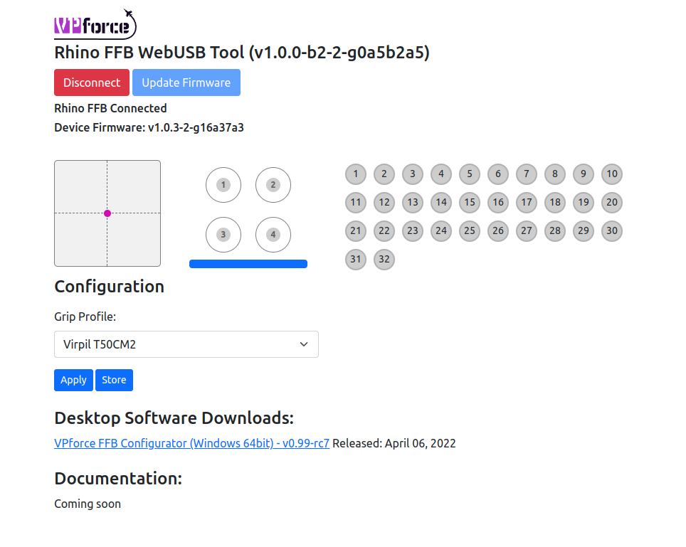
First release of device maintenance page for my FFB controller is ready! The controllers firmware will be upgrade'able over WebUSB. I'll probably move away from desktop app in the future to full configuration over the web. You can find it here: https://vpforcecontrols.com/usb/rhino/ Supporting stuff is now done, now I finally can start prepping the DYI kits for shipping
-
Honey, I developed FFB joystick (DIY)
walmis replied to propeler's topic in PC Hardware and Related Software
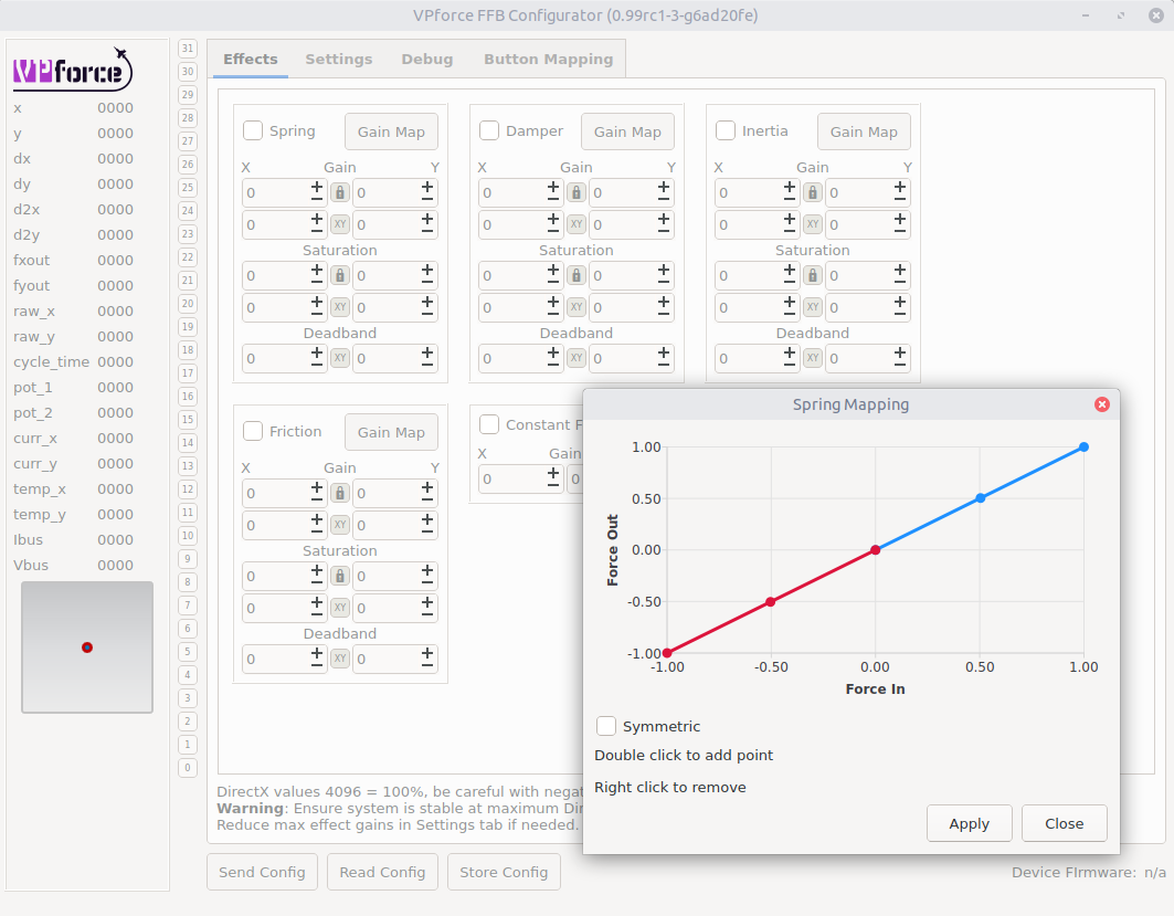
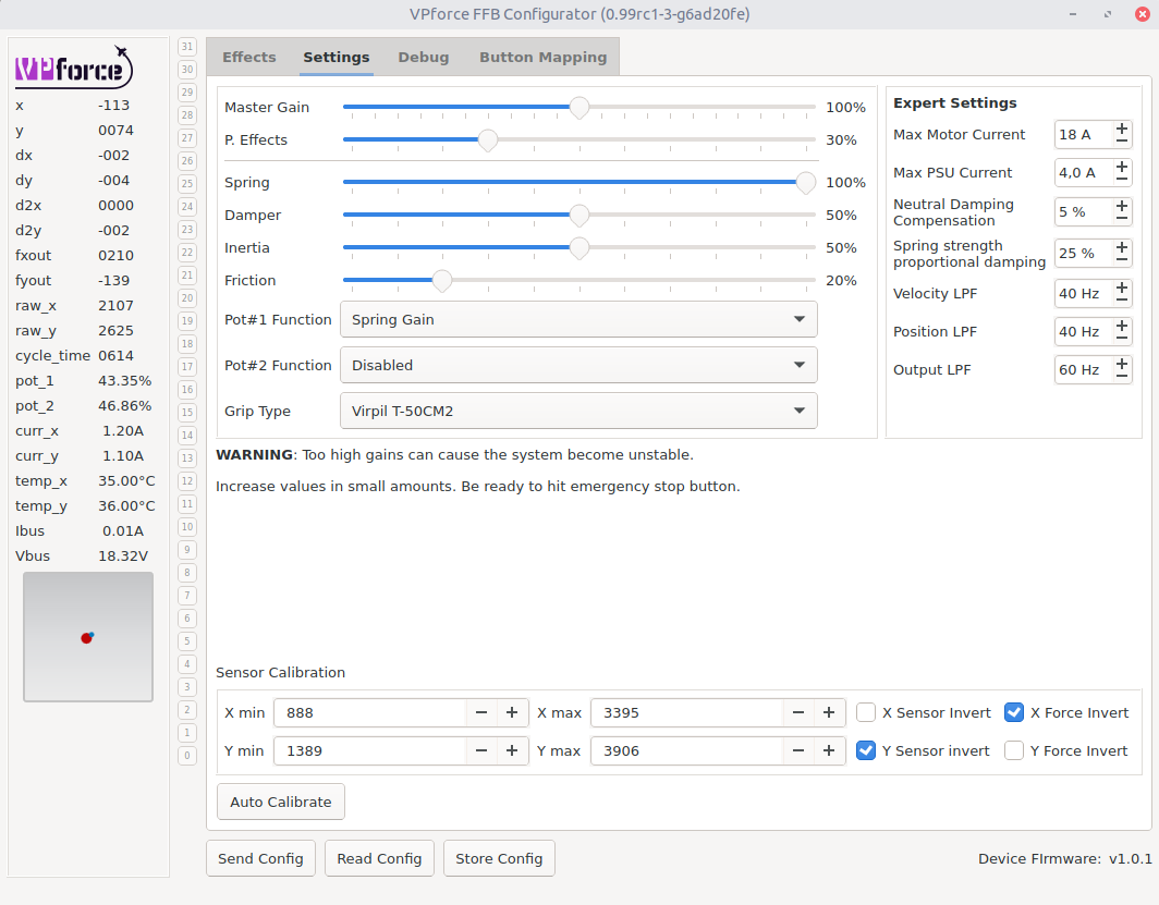
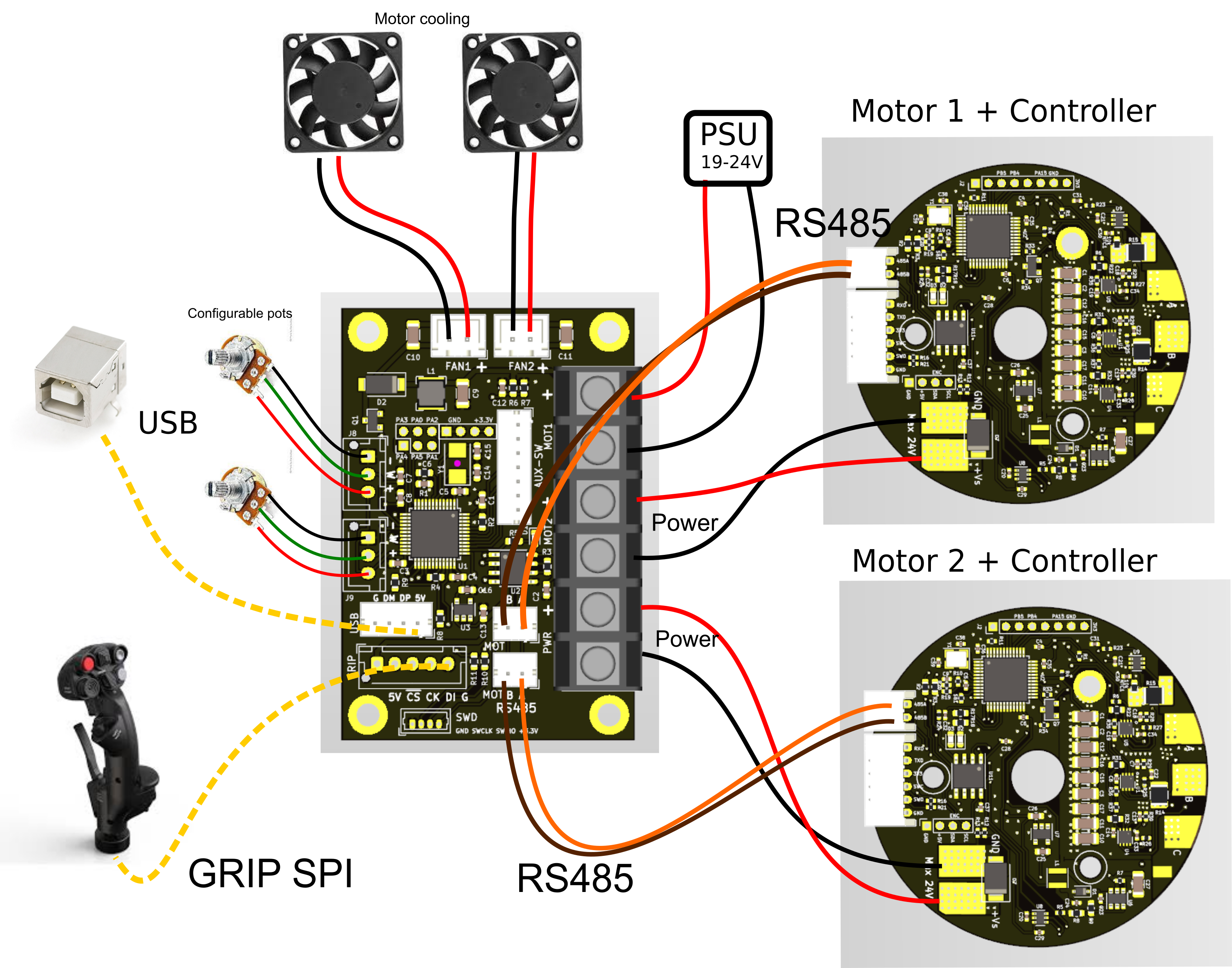
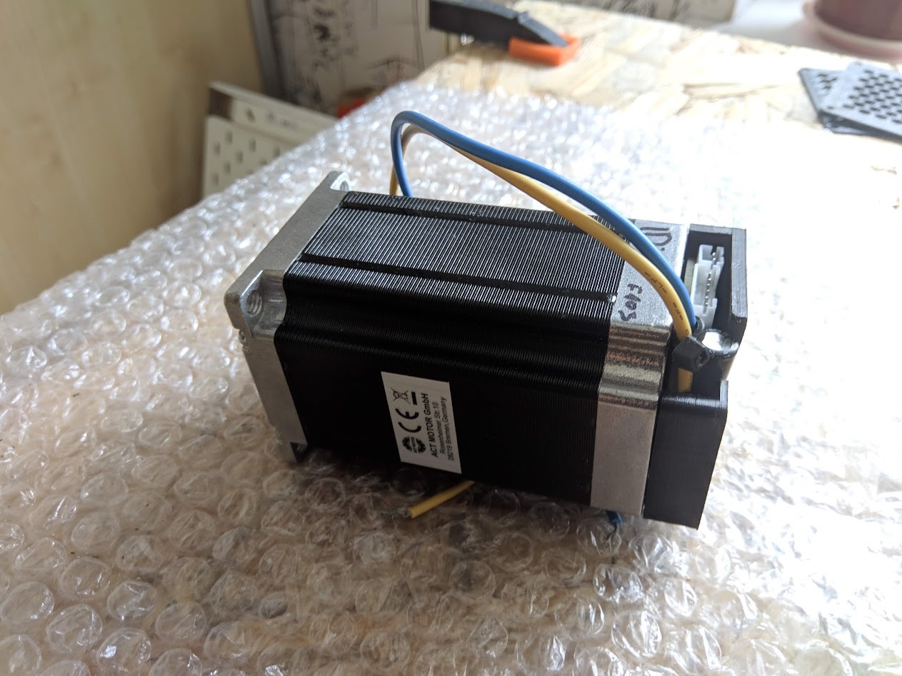
Been super busy last few months developing hardware/firmware/software for my FFB system. Pleased to say it's nearing release. I'm also building a small batch of fully plug and play FFB units and drive kits. Gonna do a photo shoot this week so will have more media to share If anyone's interested in buying a DYI motor/controller kit contact me via PM, I'll need to gauge how many components I'll need to preorder in advance. Here's a sneak peek of the software side state: This is the system diagram of connections for the DYI kit. And the assembled motor unit itself:
-
Vėl expired
-
Post MotherBoard Specs Of Bricked TM Warthogs Here Please
walmis replied to twobells's topic in Thrustmaster
Most likely communication is not working with the arduino here. I think you will need to make sure the baudrates are correct here. Check the arduino code Serial.begin(baudrate) and psocdude baudrate flag ( which is -B as I recall) -
Post MotherBoard Specs Of Bricked TM Warthogs Here Please
walmis replied to twobells's topic in Thrustmaster
Well, I'll be damned. The FSR utility actually dumped the whole ROM! tmThrottleFlashEeprom There you go guys, flash away! One thing to note, you need to save calibration data from the old chip from the last 64 byte sector. USB might not work, but HSSP should. That will save the hassle of having to recalibrate the device. I have a few spare chips, If some of you want a board fixed, let me know via PM. I'm in Europe/Lithuania. out of chips -
Post MotherBoard Specs Of Bricked TM Warthogs Here Please
walmis replied to twobells's topic in Thrustmaster
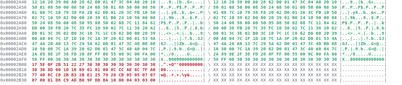
It might work if code will be executed from flash.[1] We just need to find the entry point, assemble a simple dumper program and patch the existing code and flash it using psoc dude. My guess it would be easiest to just bit-bang using any output pin and capture it using a logic analyzer. Yeah, there was a bug which should be fixed in my arduino_hssp fork. Ha. Not really, just read the same stuff out there I have attached the last *correct* dump. I used this one to reflash the chip using psocdude. And since it didn't brick, I assume it's correct Regarding the bootloader, let's not assume TM is using this bootloader implementation from the app note. Maybe they spinned their own BL which sits in front of flash. What's interesting is the vector table starting at 000014c0 which should provide some insight. There appear to be some maybe valid jump addresses. naken_util -m8c -disasm -address 0x0 warthog_throttle_dump.bin 0x14e0: 7d 1b e6 ljmp 0x1be6 7 0x14e3: 7e reti 10 0x14e4: 7e reti 10 0x14e5: 30 halt 9 0x14e6: 30 halt 9 0x14e7: 30 halt 9 0x14e8: 7d 1b e9 ljmp 0x1be9 7 0x14eb: 7e reti 10 0x14ec: 7e reti 10 0x14ed: 30 halt 9 0x14ee: 30 halt 9 0x14ef: 30 halt 9 0x14f0: 30 halt 9 0x14f1: 30 halt 9 0x14f2: 30 halt 9 0x14f3: 30 halt 9 0x14f4: 30 halt 9 0x14f5: 30 halt 9 0x14f6: 30 halt 9 0x14f7: 30 halt 9 0x14f8: 30 halt 9 0x14f9: 30 halt 9 0x14fa: 30 halt 9 0x14fb: 30 halt 9 0x14fc: 30 halt 9 0x14fd: 30 halt 9 0x14fe: 30 halt 9 0x14ff: 30 halt 9 0x1500: 7d 1a c2 ljmp 0x1ac2 7 0x1503: 7e reti 10 0x1504: 7e reti 10 0x1505: 30 halt 9 0x1506: 30 halt 9 0x1507: 30 halt 9 0x1508: 7d 03 c7 ljmp 0x03c7 7 0x150b: 7e reti 10 0x150c: 7d 1a 82 ljmp 0x1a82 7 0x150f: 7e reti 10 0x1510: 7d 1a 92 ljmp 0x1a92 7 0x1513: 7e reti 10 0x1514: 7d 1a a2 ljmp 0x1aa2 7 0x1517: 7e reti 10 0x1518: 7d 1a b2 ljmp 0x1ab2 7 0x151b: 7e reti 10 0x151c: 7d 1a f1 ljmp 0x1af1 7 I attached full assembly dump for convenience. EDIT: Did a diff with HA10T_PSOC_USB_v23 Only change is here, I'd assume it's the calibration data stored in last 64 byte page . Hmm, wonder If we could squeeze a little dumper program there and jump to it using HSSP. [1] Infineon-AN2015_PSoC_1_Getting_Started_with_Flash_&_E2PROM-ApplicationNotes-v10_00-EN.pdf section 3.3. "A running program is never prevented from performing internal reads. The romx and index assembly instructions enable the M8C processor to read from flash for any protection level. " So there IS a chance to read the bootloader! warthog_throttle_dump.hex.txt warthog_throttle_dump.asm.txt warthog_throttle_dump.bin