Duckling
-
Posts
606 -
Joined
-
Last visited
Content Type
Profiles
Forums
Events
Everything posted by Duckling
-
I got two like that for my mfcd's working with either vga,video signal or hdmi Spec state up to 1080p (i can run my down to 800x640 with no problem. Best guess is a bad main board or the video control subboard may be wacko. As said above check your used port for possible errs in settings/refreshrates etc. Youe tried another source just in case ? Pc, port on your card or say a plain video out from a cam, to eliminate If not made already check if you can get hold of a vga cabling and adapter, might be good for future projects also. - verify the used gpu port (or motherboard port) is ok by connecting other monitor/tv using same adapters used for that monitor. If nothing remains and still inop, ask seller for replacement boards or a discount on an extra set to verify Best /gus
-
one use the best, easiest and smartest solution at hand for the task, cant' agree more there. Sioc interface of a dcs pit is on the gray area there compared to at least dcsbios setup but once one get into the procedure a complete pit setup using these is not impossible Not the least expensive option though but the bundled supportsystem is great when things start to get bad ;-) Running 3usb expansion and 8 mastercards currently plus some add-ons in my A-10 pit.Dcsbios /arduinos also right now also for display handling. Cost per port is ok at least
-
@DeJohn: Can you clearify what functions you say that SIOC/OC card can't do in a DCS setup ? Agree on that many brands of cards/interface solutions are used depending on requirements, some easier to adopt then others but I find your general statement wrong here. No offence intended Best Gus
-
Thanks, good to be back. Got a nice to-do list on the way and started to to write a dcs,opencockpit/sioc implementation checklist to ease the strain on the remaining grey cells of mine :-)
-
Very nize setup. What is the optimal height/distance from HUDCenter ? Set my seat on a 3Dof car carrige and ended up way to hight
-
The sleeper has awakened... Well, not peak performing yet but at least moving.. Pit been left alone collecting dust for more than a year. Sum of obligations did grow sky high and the list of "to-do", requests, family and real life triggered the shutdown mechanism and to survive the private pitbuilding was put to pending status. Now slowly getting the time to restart that topic again. If I left some issue or request hanging, my apologies. It's like starting all over again (almost). Reconnected most of the things and found several problems. Not totally sure they was relics from past time or new that surfaced after power came back. Started troubleshooting from interface and upwards to DCS and things started to work again. Central interface system is built with OpenCockpit/SIOC with some additional DCS-BIOS/Arduinos (CMSC and CMSP handling the TFT displays). Thanks Ian ! If that had been around when I started, life had been easier :-) Was still running 1.2.x and most of the pit was ok. Made a triple backup of my SIM PC (Image, Filecopy and consolidation of all SW for the interfaced) and made the leap to 1.5.x. It worked ! (Maybe obvious to some but for me it was a surprise) Now running 1.5.2, all panel works, DCS BIOS has no issues (related to my scripts) Panels are (mostly) operational AND flight data extracts flows like a charm into SIOC. Viewport exports needs to be remade to some extent and holding my thumbs for SoftTH to respawn in a new version. Anyway, back in (pit) business again Cheers /Gus
-
Rich, you ok ? Check your mail/spamfilter please Best Gus
-
Post #176 updated Best /Gus
-
LynxDK, measuremt was made on a 10A MIP so there still is a possibility there is a slight missalignment between that and the 10C MIP. Measurement stated is as close I could get with the tools at hand. I'll doublecheck this weekend with verified tools and ping you back just in case.
-
Hi LynxDK If CMSC has same format as the 10As AN/ANR (rather sure it has) the MIP mounting hole distance are 30mm vertical and 129mm horizontal (center to center), MIP cutout is 109,4 x 47,5 mm and the holes centric placed 'round that' /Gus Edit. Just found the pics posted above of the front face and body measurements of the CMSC. AN/ANR has the same size of faceplate width and notch higher (less then .5mm). MIP Holes "should" be the same Edit #2: Verified a caliper of better quality (on a 10A MIP) (Errorlimits somewhere under 0,3 mm (used centric adapters in bolt holes) cutout. CMSC Hole distances are 119,4 (H) * 30,6 (V) mm CMSC cutout is 109,4 x 47,5 mm and the holes centric placed 'round that' Some additional info: http://www.strandedduckling.com/A-10A_Measurement_front.jpg http://www.strandedduckling.com/A-10A_Measurement_Rightside.jpg
-
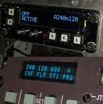
Both that and other posts 'all over' ;-) Building techniques, tech approach for guages to name a few and quality focus in all is impressing. Don't stop please. (Arthritis is hell) Your CMSC OSRAM implementation will be great to follow ! No and No. My CMSC is close to 129*46 mm and the OLED 2row Display area is near 72mm (96 is total width). (the AN/APR same placement in A-10A has same dimensions and mount as the CMSC but I nudged the front of CMSC down a bit to ease space for the VVI and RWR display in my rig) Even if it's Q&D approach, it enable the text to appear close to where it does in the real thing. Rightmost LEDs and knobs had to be moved down a bit to make space for the display though. The Unused part of the display will be covered with the now missing lightpanel/frontplate Edit: @Anton: Thanks, found a local supplier for a 'Green Stage filter Gel'. Ordered and will try it out Edit #2: Just reread the answer to Nikolas_A and found it may sound harch. Note to self:avoid posting during workhours. No offence intended Best Gus
-
@Anton, Thanks. I've made some basic testing with green colored plastic with allmost no effect visual change (still White-ish). What material do you suggest ? (got a link ? searching for a material of max 1 mm thick if possible) @Firedawg, strive for perfection isn't a bad thing here but CMSC Panel total width and hight, is true size here. The display is a bit short in hight but horisontal spacing and character placement is very close to the real thing. Lightpanel/faceplate will be adjusted to cover the excess areas and textures adjusted. Agree on OSRAMs whould be ideal but out of scoop for me due due to cost
-
Hi John, not near finished status of either CMSC or CMSP. I use same I2C 2x20 OLED as Peter on my CMSC (I think). Couldn't get the link posted to work but sure it was active on eBay some weeks ago. Display is easy to connect and interface, space efficient, clear contrast but White. Not perfect but close. Got to replace my oldie 2x16 TFT in the CMSP but haven't yet Complements on your build thread, a true inspiration Best /Gus Edit: http://www.ebay.com/itm/IIC-I2C-2002-20x2-OLED-Module-Display-Arduino-Example-/200982177125?hash=item2ecb78a565

-
Is my video card performance not satisfactory?
Duckling replied to SayusiAndo's topic in PC Hardware and Related Software
Might be off here but reading the above sounds you have both an axis and keys assigned ? Try unbind the axis control if so -
Ah ok.
-
@A10C-Wolf, thanks, but please don't ditch it ;-) Know earlier A mod throttles both handles and linkage needs "some" work to be useful. The feeling of the real throttle is something extra but TMWT do make it a lot easier though, as I'm sure you found out already. Did see some pics years back of the real handle restauration/upgrade but don't remember where (could been here in DMs thread but can't say). DM might know
-
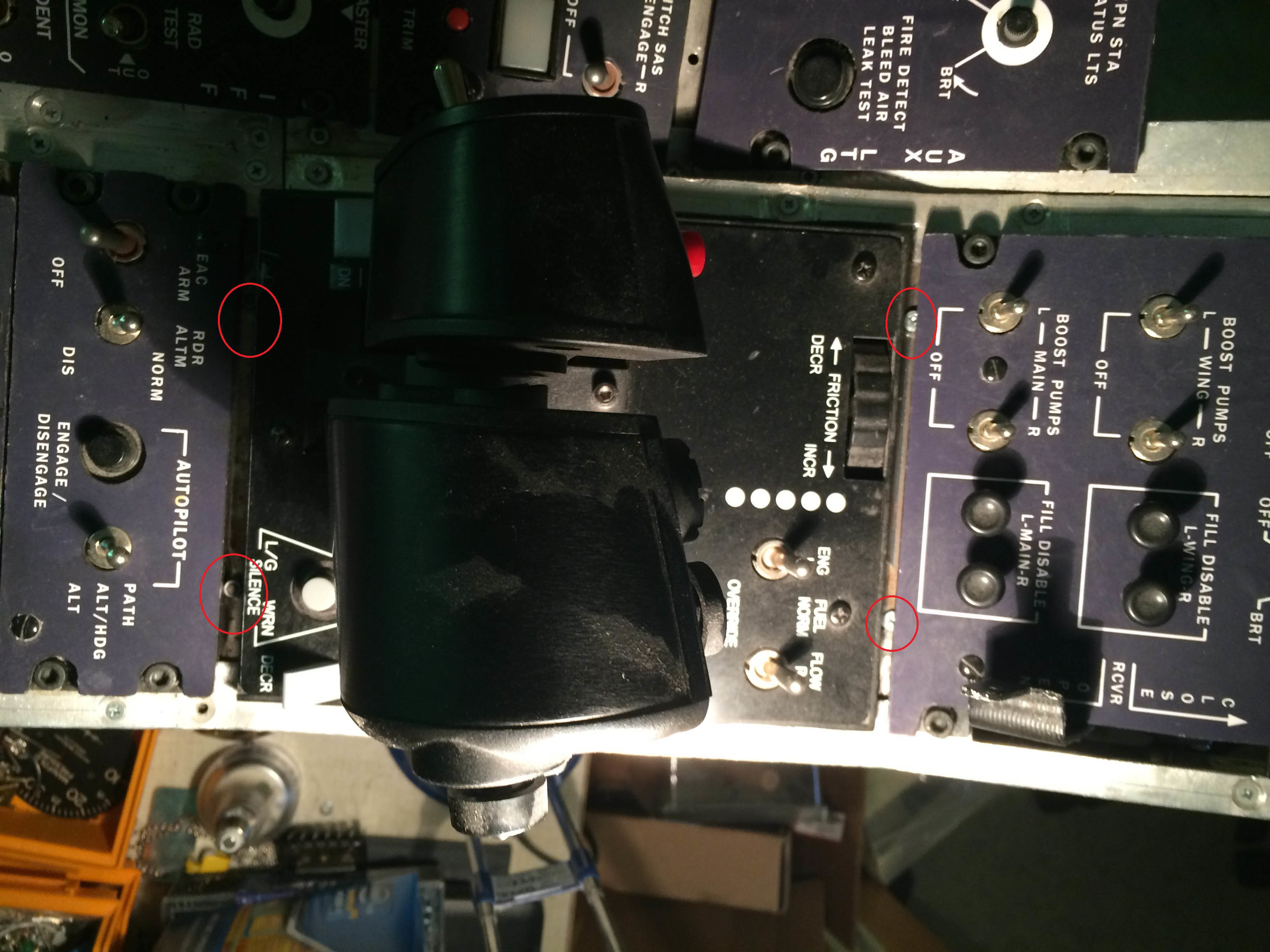
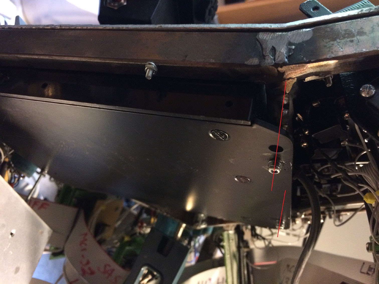
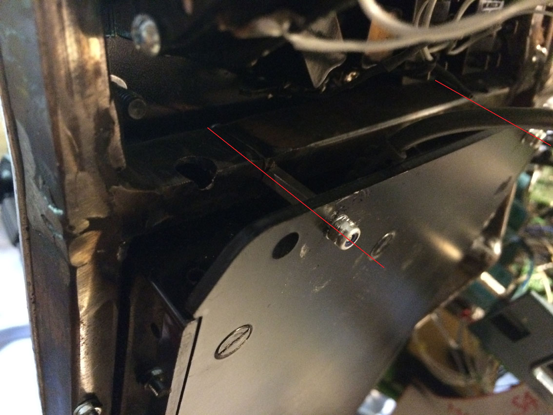
It's a very crude work on the throttle but it works. The Laste quad is cut of at the detent where the 'lightpanel' ends. The base bottom metal plate and side plates was removed to squize down the dims of the package. Prior that the PCB of the LASTE and connecting cable was removed ofc, very easy to do. The cable to the 'Horn Silence' button is connected to the Laste PCB and now patched to one of my IOCard inputs instead. The remaining metal base was cut in rear ;-) to leave a flange (front and aft) to bolt up into the frame in to prepared place. Fixated the top of the throttle case to the metal plate base also to eliminate the flex, a requirement when the mateal sides is removed. Can one way to enable the possibility to use either real throttle or the TMWT be to build a module for each that fit the true frame size ? A bit 'LEGO' and not sure if the width of the rightmost 'lane' can fit the slight wider TMWT without extrude into the hub. /Gus Edit: Ky, congrats to the seat cover ;-)
-
Hi David. Long time, welcome back. /gus
-
Real Throttle assy outside dims are aprox 140mm (width) x 180mm (lenght) with bolt to fasten it from front and back side through the real frame. The TM WT with Laste panel cut of, and the metal sideplates removed is close to 146mm width and 186mm length (in my case). I removed the TM Laste PCB and cut of that complete part from rest of the throttle. Managed to squeze it down in my frame. I got 148 mm inside dims of each 'rail'. The new assembly was then fasten with bolts from underneath, through the TM WT bottom metal plate, inte the rails of the frame. Only part except the Laste PCB that needs to be interfaced with other means is the 'Horn Silence' button that is connected to the same Laste PCB. A bit rough but it works fine. If DMs true panel inside dims fit the TMWT (or can be adjusted), it could be a solution if not the real throttle is to be used (and warranty is no were to be found after that :music_whistling:)
-
Looks very impressive Mike. Follows it with great interest and sure result will be great. Got a load of syncros standing by ;-) Best /gus
-
Got to raise my insurance :-) wish my pensionfond incresed in same rate...
-
Hi Harsu. 6k ? I know the cost increased a bit throgh the years but I got them for 50$ a piece some years back.
-
Major Announcement: New software to to connect panels to DCS
Duckling replied to FSFIan's topic in Home Cockpits
Thanks Ian. Very impressive rwork. Got one newbie question that i probably missed in the docs, can you describe the procedue (or refer to where in the refs) a best practise to implement multiple Arduinos to DCS-BIOS ? I also 'vote' you include a donation button or a Paypal 'buy a beer' address ;-) Cheers Gus -
Major Announcement: New software to to connect panels to DCS
Duckling replied to FSFIan's topic in Home Cockpits
Thanks Ian. Very impressive work. Got one newbie question that i probably missed in the docs, can you describe the procedure (or refer to where in the refs) a best practise to implement multiple Arduinos to DCS-BIOS ? I also 'vote' you include a donation button or a Paypal 'buy a beer' address ;-) Cheers Gus -
[opensource] A-10c EMI gauge with arduino and PCB KiCad file...
Duckling replied to overpro's topic in Home Cockpits
Who am I to judge ? ;-) Looks great and you way ahead of me, thanks for posting OverPro.