FSFIan
-
Posts
1301 -
Joined
-
Last visited
-
Days Won
7
Content Type
Profiles
Forums
Events
Everything posted by FSFIan
-
How well can I control the Hornet with a UFC, ODU and two MFDs?
FSFIan replied to FSFIan's topic in DCS: F/A-18C
Thanks for the insights. I'll get the Hornet and see how far I get by operating the AMPCD with the mouse. If I find I need to use a few of the OSBs on it frequently to the point that clicking them is annoying me, I can map them to the HOTAS or build a tiny dedicated button box. The F/A-18C should give me a nice fallback option for those times on multiplayer servers when ground-pounding in the Harrier simply is not an option because of enemy air cover and no friendly CAP. I don't know how much time I can devote to learning its systems and A2A tactics, but the least I can do is take off and lob a few SPAMRAAMs in anger. -
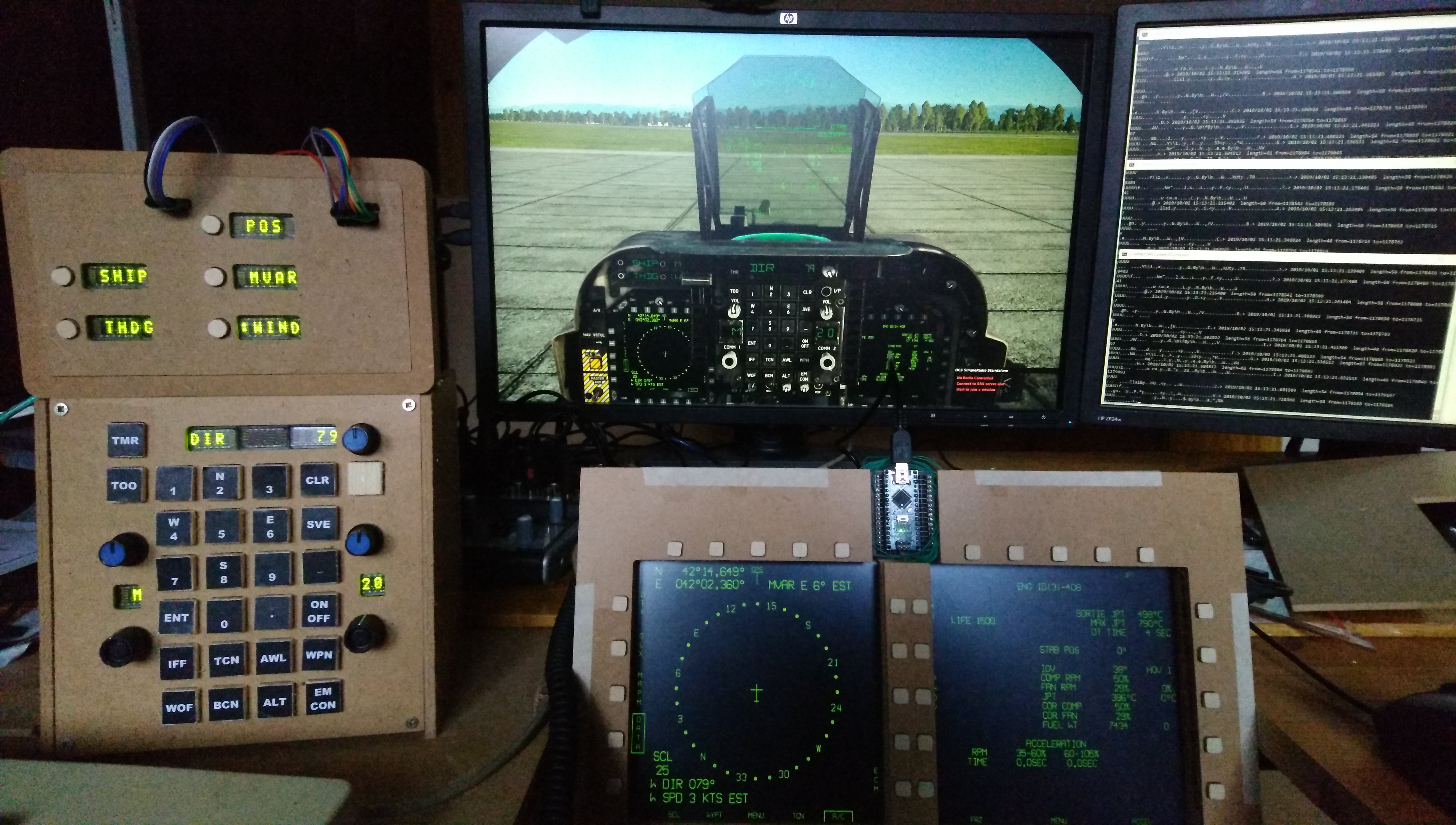
Hi, given that I have cobbled together a working Harrier UFC, ODU and MPCDs which would translate very well to the Hornet, I am considering to buy it this sale. In the Harrier, once I have started it up, everything I use regularly is covered by the custom panels and my HOTAS. I'd like to know what the third display in the Hornet is typically used for, and how much only having two MPCDs will affect my ability to operate a Hornet without using the mouse. (I don't have the space, monitor or time to add a third MPCD in the short/medium term.) For example, I could export the third display to my right monitor, it just wouldn't have any buttons. How much hassle is it to temporarily swap display contents around? Is there any "quick swap" feature similar to coolie hat down in the A-10C? Here is what my setup for the Harrier looks like:
-
Big difference #1: socat got replaced by the "DCS-BIOS Hub". That means no more harmless but confusing "could not compute FAST_CWD pointer" error messages, a web-based graphical interface to connect and disconnect COM ports, and thanks to the "autoconnect" settings on the COM ports and the "Autostart DCS-BIOS" setting, no need to (remember to) manually start the socat script(s) before playing DCS. The DCS-BIOS Hub uses only TCP to communicate to DCS: World, as UDP can lead to harder to debug issues and generally more trouble with firewalls. You can still start the DCS-BIOS Hub before starting DCS; it will re-attempt the TCP connection until it succeeds. Big difference #2: The DCS-BIOS Hub integrates the interactive control reference documentation, so you don't need to install a Google Chrome extension in development mode for that anymore (which Chrome will nag you about every time you launch it). Big difference #3: It comes in a standard .msi installer package, so installing and upgrading is quick and painless. It can also modify Export.lua for you, so you don't have to modify that manually. It will add a dofile(...) statement that points to its installation directory to Export.lua, the Lua scripts now live under C:\Program Files\DCS-BIOS\dcs-lua. If you have custom modifications, that is the place where you need to apply them. (Probably less hassle if you install to a non-system location where normal users have write access.) Note that in the A-10C, the path to the CDU JSON data has changed, see this commit for the change you need to make. Also make a backup of your changes, I assume the installer will overwrite them on upgrades. What changes did you make? Big difference #4: it's a solid foundation for additional features. As the DCS-BIOS Hub is no longer a Lua script inside DCS: World, it has access to any library it wants to use and can do more calculations without impacting DCS performance. Use 2% more CPU when everything you do stops the sim? Not good. Use 2% more CPU on a different core? Nobody cares. This opens up the possibility for interesting future improvements, such as a Websocket API so people can build virtual panels with HTML and JavaScript that run on any device with Wifi and a web browser, or the ability to map commands from your panels to keyboard actions or a vJoy feeder so you can use a DCS-BIOS powered simpit for other games as well. Extra hidden bonus feature: The ability to remap inputs to a different DCS: World module is already implemented, there's just no UI yet: https://github.com/dcs-bios/dcs-bios/commit/b47b5517c1229a3e45ba0ceedde0e92b20648091 I use that to make my Harrier MPCDs work for the A-10C MFCDs and the Ka-50's ABRIS buttons. Yes, they are. I had planned to use OLEDs, but then saw a surplus of 40 HCMS-2963's on eBay. I realized 40 might not be enough if I build everything I can think of (Harrier UFC+ODU, A-10C RWR and CMSP, kitchen timers, ...) so two days later, the seller auctioned off the last 200 pieces and I got another pack of 100. In total, I got 140 of these for about EUR 1.60 a piece. I won't need all of these, so if anyone needs some for their simpit build, let me know. I'll part with these for EUR 1.60 + shipping as long as I know they'll end up in a simpit. I also made some modifications to the LedDisplay library so I could daisy-chain ten of these: https://github.com/jboecker/LedDisplay
-
If it comes with a driver board that accepts something standard like HDMI, DVI or DisplayPort (but without a frame), I'd pay about $100 a piece + shipping. I have been looking for square displays so I could actually mount my UFC "up front" between the MPCDs in the Harrier. Found a single seller on Alibaba, with a large price range, and haven't bothered to ask what they'd want for two pieces. I'd take two, maybe three displays (let's face it, I already have a UFC+ODU for the Harrier, that's just asking to buy the Hornet this sale!).
-
I am not, but I am about to change that.
-
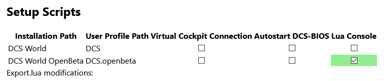
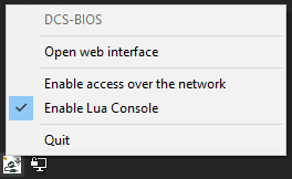
Hi, since some people who might find this useful will miss it if it's just mentioned in the Home Cockpits forum, I'll drop a note here. I have published a pre-release of DCS-BIOS v0.8.0 that includes a Lua Console that can help you debug your mission scripts. How to set up: Download the MSI installer and install the applicaton start the DCS-BIOS Hub using the start menu shortcut Click the icon in the system tray and click "Open web interface". A configuration page should open in your browser. Select "Setup Scripts" on the left and activate the Lua Console: This installs a file in the Scripts\Hooks directory. How to use: start the DCS-BIOS Hub Make sure "Enable Lua Console" is checked in the systray menu: This is a security precaution; anyone who can connect to the web interface of the DCS-BIOS Hub can then execute arbitrary Lua code on your machine. If you also check "Enable access over the network", the web interface will be usable from other machines on the network (point a web browser to <your-LAN-ip>:5010) -- obviously, you should only do this on a LAN that is firewalled from the public internet. Start your mission Open the web interface and click the "Lua Console" menu item. Set the "Environment" dropdown menu to "mission" Type in some Lua code, then press Ctrl+Enter to execute it and show the results. Some useful snippets to try: return list_cockpit_params() return list_indication(n) (set n to a small number; start at 0 and work your way up.) return c_flag_is_true(42) to check the status of flag 42. a_set_flag(42) to set flag 42. a_clear_flag(42) to clear flag 42. a_set_flag_value(42, 23) to set flag 42 to value 23. return a_do_script([[ trigger.action.outText(trigger.misc.getUserFlag(42), 5 , false) ]]) to show the value of flag 42 as a cockpit message local keys = {} for k, v in pairs(_G) do keys[#keys+1] = k end return keys to see what else is available.

-
The DCS-BIOS module is called "FA-18C_hornet". The DCS: World subfolder under "mods" is probably called something different so it does not recognize that those belong together. Don't worry guys, the job hunt is proceeding well, and while I am still looking I get to collect unemployment insurance and bring DCS-BIOS to a position where I can continue to maintain it without being a bottleneck :)
-
I have published a pre-release of DCS-BIOS 0.8.0 here: https://github.com/dcs-bios/dcs-bios/releases/tag/v0.8.0-pre2 Update: v0.8.0-pre2 is out, this no longer crashes if no serial ports are found. If you already installed -pre1, you'll have to uninstall that from the "Add or remove programs" control panel, otherwise the installer will complain that a v0.8.0 is already installed. If you try it, please let me know of any issues in the DCS-BIOS 0.8.0 prerelease feedback thread.
-
I have published a pre-release of DCS-BIOS 0.8.0 here: https://github.com/dcs-bios/dcs-bios/releases/tag/v0.8.0-pre1 There is no documentation yet, but most things should be pretty obvious if you have used DCS-BIOS before. After you run the program, it will look like nothing happened, because all it does is start in the background and add a systray icon. You can click the systray icon to show a menu which lets you open the web-based configuration interface, or just point your browser to http://localhost:5010 . I'd like to apologize for my long absence from these boards and DCS in general. After I got a full time job about two years ago, the amount of time and energy I could devote to DCS-BIOS maintenance rapidly decreased. Another issue was that I did not have an easy-to-use test setup for DCS-BIOS development; everything was solderless breadboards and a mess of wires. Over the last year, a few things happened to change that. I moved out of the city where I studied back to our family home, where I have access to a workshop and no one is inconvenienced when you fire up power tools at 8pm. I replaced my chinese 1610 CNC toy with a machine that is 10x as expensive but 100x less hassle. I bought the Harrier in a sale and instantly got hooked. Then I lost my job two months ago. While it is annoying to have to look for a new job, it also meant I had a bunch of time to build a UFC, ODU and MPCDs (see attached screenshot) and get a head start on a new DCS-BIOS version, which is now in a state where I can improve it in smaller increments. I'll try to catch up on the PMs I have missed and the GitHub issues I have been ignoring over the next days. I'd also like to thank ArturDCS and BlackLibrary for forking DCS-BIOS and adding support for a bunch of modules. Allowing forks like this in case I could not continue to maintain the project was the reason it was open source from day one, but I wouldn't have expected anyone to pick this up given the sparse amount of developer documentation.
-
From what I can tell, there are two different input systems in DCS (or maybe two different conventions of using the same system). One is used for most keybindings and joystick controls; a command consists of a command ID, usually specified in the keybinding Lua files as one of the iCommand... constants. I will call those "normal commands" in this post. The other system is used for clickable cockpits. A command consists of three numbers: a cockpit device ID, a command ID, and an argument. I will call those "clickable commands". (I suspect that "normal commands" are the same as "clickable commands" with no argument value specified and the cockpit device ID set to 0.) Let's take the AV-8B's OSB 1 button on the left MPCD as an example. In mods\aircraft\AV8BNA\Input\AV8BNA\joystick\default.lua, the keybinding is specified as follows: When you push the joystick button, iCommandPlaneLeftMFD_OSB1 is sent to the airplane and it will activate the left OSB1. When the button is released, iCommandPlaneLeftMFD_OSB1_Off is sent. In mods\aircraft\AV8BNA\Cockpit\clickabledata.lua, the NAV master mode button is defined as follows: Using the definition of default_button from clickable_defs.lua, some guesswork, and some experience with DCS-BIOS, I think that when the mouse button is pressed, the "clickable command" (26, 3200, 1) is triggered (send command 3200 to cockpit device 26 with argument 1) and when the button is released, (26, 3200, 0) is triggered. Also, the first command changes cockpit argument 200 to 1.0, the second one changes it back to 0. Cockpit arguments control animations in the 3D model. The IDs of cockpit devices can be found in mods\aircraft\AV8NA\Cockpit\devices.lua (MPCD_LEFT = 26). The command IDs can be found in command_defs.lua in the same folder (mpcd_l_commands.Button_01 = start_command + 200 = 3200). Note that with the "normal command", the cockpit argument 200 never changes value. You will also note that when you trigger OSB 1 through a key binding instead of with the mouse, the button click is not animated on the 3D model and does not make a sound. The Harrier training missions notice button clicks by looking at cockpit arguments. That is the reason why they do not notice when the actions are done using the keyboard or joystick. So now that we understand the problem, how can we solve it? Sometimes we are lucky and we can check for the result of the button press, instead of the button press itself. For example, we could tell whether we are in A/G, NAV or VSTOL master mode by looking at the cockpit arguments that control the indicator lights in the respective buttons. (This would, for example, also detect entering A/G mode because the TOO button was pressed.) A/G mode is argument 281, NAV mode is 283 and VSTOL is 285. But this does not work for every button and finding the correct argument number with the model viewer takes some effort (you can do a binary search by playing around with the animations). The other option is to monitor both methods: for OSB 1, we already know that we can monitor cockpit argument 200 to see if the button was clicked (which already happens in the training mission), but we also want to know if iCommandPlaneLeftMFD_OSB1 is triggered. First, we need to find out which number iCommandPlaneLeftMFD_OSB1 represents. To do so, edit MissionEditor\MissionEditor.lua and set OPTIONS_ADD_COMMAND_CODES_TO_TOOLTIP = true at the top of the file. Then go to the "adjust controls" screen and hover the mouse over one of the cells containing a keyboard or joystick binding. This way, we can find out that iCommandPlaneLeftMFD_OSB1 is number 642. Now we can use the trigger "X: START LISTEN COMMAND" (command = 642, flag = 500, hit count=1, cockpit device=0) to set flag 500 whenever iCommandPlaneLeftMFD_OSB1 is triggered. Instead of looking at cockpit argument 200, we can also use "X: START LISTEN COMMAND" to set the same flag when the button is clicked with the mouse, by specifying command=3200, flag=500, hit count=1, cockpit device=26. I have attached an example mission that displays a message whenever the left OSB 1 is pressed either through a key binding or with the mouse. Thanks for the amazing and fun training missions by the way. I am having a blast with the Harrier! Cockpit Trigger Demo.miz
-
Hi everyone, here's a short update about the current state and possible future of DCS-BIOS. In October 2017, I stopped studying Computer Science and started to work full time at a web hosting company. Before that point, progress on DCS-BIOS was already slow. After that, it ground to a complete halt. I thought this would be temporary -- that the job would become easier as I gained experience and I would find time and energy to hack on DCS-BIOS again. Unfortunately, that was not the case. Because my employer's web hosting platform is built around a closed-source third-party product, I could not improve my understanding of the system to a point where I would be confident that any configuration changes I was considering would not break anything. This uncertainty caused me a lot of stress. I am sorry for my lack of communication over the last months. I didn't know what to write because I did not have any good news to share and I did not want to admit to myself that the project was dead. Fortunately, now I do have some good news. (1) On June 23 (only five more weeks to go!), I will go on a three week vacation. I am going to visit Warhog in Canada, where we plan to work on his cockpit and DCS-BIOS. (2) When I return from my vacation, I will start at a new job. I found a position as a software developer not far from my parents house. This means I can move back to the country, commute by bicycle instead of public transport, and when I come home from work I will have access to space, a good selection of tools and the neighbors are far enough away that nobody is bothered if I use power tools at 9 PM. Under those circumstances, it is inevitable that I'll start working on some kind of simpit of my own, probably a small collection of multi-function panels which will serve as a test bed for DCS-BIOS 2. Unless there are some unforeseen nasty surprises on the new job (unlikely, but you never know how horrible and headache-inducing a codebase is until you have worked with it for a few weeks), things are looking well for the future of DCS-BIOS.
-
Hi everyone. I had a week of vacation last week. The plan was to work on the next DCS-BIOS version and answer forum questions about the current version. But no plan survives first contact with the enemy. The enemy turned out to be eBay, which made me realize how inexpensive entry-level CNC mill kits have become. My apologies to everyone whose questions I have ignored all week, I was distracted by the shiny thing that arrived in time for my vacation: The image shows a 1610 CNC kit I got for 185 Euros. The work area is 160x100 mm. The Z height you have to work with depends on the length of the bits and the thickness of the sacrificial board. With the 38mm long bits I ordered and a 7mm sacrificial board, I get about a centimeter of useable Z movement. The machine comes with 10 cheap 10 degree engraving bits with a 0.1mm tip. On Warhog's advice, I purchased some decent quality engraving bits and end mills from a local supplier. ****-ups and fixes The machine arrived three days before my vacation and came flashed with grbl 0.9, which is an open source CNC controller. The current version is grbl 1.1f, and whoever designed the control board ("Woodpecker CNC") did not bring out all of the pins needed for in-circuit programming. ...so the first thing I did was to solder some wires to it, and tried to update the firmware. That did not work immediately, and while debugging the issue I managed to short something out and fried the on-board ATMega328 chip. I ordered a replacement board just in case, then pried off the chip and attached an Arduino Nano (with current firmware) instead. That worked, but I had some issues where the stepper motors would randomly do their own thing and crash the bit into the mill table. I found out later that this was caused by the probe cable being too close to the cable for the spindle power supply, but this issue made me switch to the new controller board (an Arduino Uno with a CNC shield). The switch to the new controller board also meant that I am now running the steppers on 24V intead of 12V (I checked the part number on Google, they are rated for 12V to 24V operation). After that, I managed to get the machine running. I have mounted the old controller board (which I still use for the connectors and the MOSFET that switches the spindle power) and the new controller board in the case of a broken ATX power supply. The case came with a fan which draws about 100 mA at 5V, so I attached that to the Arduino's 5V line. The stepper drivers used to get pretty warm (not too hot to touch though). With the fan, I can hardly tell that the machine has been running after I turn it off. The first thing I made was the small PCB. That proved that the machine can do what I bought it for: make PCBs suitable for SMD soldering of SOIC packages. The second product was the small wooden box, which I designed as separate 2D drawings in Inkscape. That's where I found out that milling something like this can take quite a while (about 1.5 hours for this 5x5 cm box). If you have a new tool, you will want to buy more tools After making the small box, I knew I needed a faster way than milling to cut wood and acrylic. I also wanted some way to cut material stock to size before milling. After some research, I purchased a cheap scroll saw (73 Euro). The Einhell TC-SS 405 E has an adjustable speed range from 400 to 1600 RPM. At low RPM, it was very quiet when I tried it at my parents house. Once I moved it to my apartment, it made the whole floor shake. I tried placing it on a piece of styrofoam, which had no effect at all. Then I tried placing it on a blanket (wrapped in a trash bag to protect it from dust). That works remarkably well. At low RPM, it now sounds like a sewing machine. If I adjust the holding mechanism so the 4mm plywood gets pressed firmly against the saw table, then even while cutting wood the vacuum cleaner is louder than the saw. For the large box, I used the CNC mill to mark the cutting line and then cut the thing out with the scroll saw. I used the blade it came with, which was a bit too coarse for the job. To design the large box (12x7x2 cm), I wanted to use a 3D CAD program. After trying FreeCAD and getting frustrated with it, I found SolveSpace. SolveSpace is still in early development, so it does not have many features. That also means it has a clean interface that does not overwhelm a beginner. It does not support variables, but you can import one sketch file into another and then use "equal length" constraints against lines from the imported file. I used that to define the length, width, height and material thickness of the box once and re-use those values for all three sides. If I want to make a smaller or larger box of the same design or cut one out of a different material, I only have to modify a single file. Unfortunately, I did not find a way to export just the outline of a face, so I ended up retracing two of the three sides in Inkscape. I'll have to look into this some more, there has to be an easier way to do this. You'll spend more than $200 on a sub-$200 mill All things considered, I spent close to 500 EUR on the mill, scroll saw and accessories. Here's a rough breakdown: CNC Machine 185 EUR New Controller Board (Express Shipping) 30 EUR Drill Bits 52 EUR Scroll Saw 73 EUR Saw Blades Cordless Drill 70 EUR Digital Calipers 13 EUR Feeler Gauge 10 EUR Materials 50 EUR Workflow and end mills For anyone curious, here is the workflow I use: I draw my plans with SolveSpace. Some 2D exports require some post-processing in Inkscape. The G-Code is generated and sent to the CNC mill with bCNC, which can also do autoleveling for PCB milling. For PCBs, I use KiCad to draw the PCB, pcb2gcode to generate the G-Code and bCNC to send it to the machine. The stepper motors are controlled by an Arduino Uno with a CNC Shield, running grbl v1.1f. Review The machine does what I purchased it to do -- it enables me to make single-sided prototype PCBs and is accurate enough to create 20 mil traces for SOIC packages. , It does not come with any assembly instructions. Fortunately, someone has done a review of the machine and posted build instructions on his website. My machine was slightly different, but I managed to assemble everything in one day. The process can be a bit annoying at times, but it is not difficult. I don't know how suitable this machine is for building a home cockpit. I'll probably find out soon enough. I don't have plans to build a simpit, but with the machines to do so now always available, I see some multi-function panels in my future. Looking at this machine on my desk now, I realize that a 3020 would also fit on this desk. On the other hand, even when realizing this before, I probably wouldn't have spent $500 on a machine without knowing if I could get it to work beforehand.
-
When the mega is powering up and sees data on the serial port pins, it will try to interpret it as a program to be uploaded. In that case, it can get stuck in bootloader mode -- it does not time out and switch to your program like the other boards do. For the RS-485 master, we solved this problem by adding a delay of a few seconds in the connect-serial-port.cmd script. If you are using a Mega as a slave device, try disconnecting it from the bus, pressing the reset button, and then connecting it. A more reliable method is to upload the program to your Mega boards using an ISP programmer instead of the serial port. That way, the chip will not contain the bootloader and will boot straight into your sketch every time. You can use another Arduino as an ISP programmer. You can also buy an inexpensive programmer from eBay (less than $10). I have an USBTinyISP and an USBASP. Both can be used to upload a sketch to the Mega, but IIRC one of them cannot be used to put the bootloader back again if you want to program the Mega with the serial port again.
-
What the "best" controller board is depends on your application. There is a spectrum that ranges from buying off the shelf hardware (costs a little more, but you get a turnkey solution) to writing your own firmware (lots of work, extremely cheap hardware, ultimate flexibility). Derek Speare Designs, GroovyGameGear and Leo Bodnar all offer commercial solutions to your problem. The different boards have different prices, number of input pins, wiring schemes (keyboard matrix or not) and additional features (analog inputs, ability to use rotary encoders). You can also build your own by uploading the correct firmware to a suitable microcontroller board. There is a thread here on the forums by overpro where he uses an Arduino Mega, there is MMJoy2 which can generate firmware for the Arduino Leonardo, Pro Micro and others. You can also learn how to program microcontrollers in C++, bang your head against the USB specification, and roll your own USB device with the awesome V-USB library, which implements low-speed USB entirely in software: I'll admit that this one was only worth the time it took to build because I learned a lot in the process. The lower rotary encoder changes the panel that you are controlling. It shows up as a composite USB device with one 32-button, eight axis controller for each panel. I also found out that Windows will not accept more than 16 joystick devices at once...
-
A low-cost way to attach a small TFT display module over USB
FSFIan replied to FSFIan's topic in Home Cockpits
You can configure DCS to put a copy of a display on a second monitor, so you can grab it from there. This works out of the box for the two MFCDs, and with some editing of Lua files for most of the other displays in a clickable cockpit (e.g. the RWR, CMSC, CMSP, or CDU in the A-10C -- anything that gets rendered as a flat texture instead of being a part of the 3D cockpit model). That should work. I took a quick look at the datasheet. With that display, the EZ-USB chip is no longer slowed down by the timing requirements of the display, so the data rate could increase up to 2.3x compared to the 320x240 TFT with the SSD1289 controller. On the other hand, it has 5x more pixels than a 320x240 display. I would expect about 14 fps. In practice, we could probably achieve ~30 fps again if the host software gets optimized to only send the parts of the frame that have changed, as large parts of the display will be static most of the time. -
A low-cost way to attach a small TFT display module over USB
FSFIan replied to FSFIan's topic in Home Cockpits
Looks like it would, at least these guys use a 320x240 display. http://www.driven-technologies.com/simulated-flat-panel-displays/simulated-military-displays/f-18-integrated-fuel-engine-indicator-ifei.html I don't know how hard it is to find one in a 5.5 inch size though. You might be able to use two smaller displays in portrait mode instead. I don't know the F-18 well, so I don't know where this display would be in relation to the pilot, but if you are not going to be looking straight at it you might want to find an IPS panel instead of a TFT -- on these cheap TFTs, the colors change drastically with viewing angle. -
A low-cost way to attach a small TFT display module over USB
FSFIan replied to FSFIan's topic in Home Cockpits
DisplayLink is definitely the way to go for high resolutions. This board could probably handle a 480x320 display (for the SSD1289 the EZ-USB has to slow down a bit to meet the timing requirements), but if you go higher than that the frame rate will drop (this is not such a problem for DisplayLink chips -- I have a 1600x900 DisplayLink monitor that works remarkably well on a USB 2.0 port, so their controllers must have enough computing power to implement compression algorithms). The advantages of this approach are the low cost (for the price of one DisplayLink adapter, you can get all the parts you see in the video) and the ability to talk to displays in small and weird form factors that might not be available with an HDMI port. -
I finally got some time to tinker again. The following video shows a 320x240 TFT display module attached to a Cypress EZ-USB FX2LP development board: The software and wiring instructions can be found at: https://github.com/jboecker/fx2-usb-display You can blame ArturDCS for this, this whole thing is the result of a discussion we had on Discord when he told me he could not get Saitek's Flight Information Panels to work with DCS. The first idea was to use an Arduino Due, but that was too slow (mostly because while the Due has 32-bit I/O ports, the pin headers do not bring out one complete port, so the firmware needs to do a lot of bit shifts to put the right bits on the right pins). Then I stumbled upon the Cypress FX2LP. This is the same chip that is found in the $10 logic analyzers from eBay. It has an 8-bit 8051 CPU that is a bit slower than an Arduino Uno, but it has a fast data path between USB and a 16-bit parallel interface that does not involve the CPU at all (it only sets things up and then gets out of the way). If you search eBay for "CY7C68013A", you will find development boards with this chip for less than $5. The current software can take a 320x240 rectancle from your screen and send it to a 320x240 TFT module that is attached to one of these dev boards and has an SSD1289 compatible controller chip. There are 5 unused GPIO pins and an I2C bus on the board that could be used to attach a few push buttons or rotary encoders in the future. The board runs on 3.3V, but all inputs are 5V-tolerant.
-
DCS Bios pointer calibration tool - gauge calibration
FSFIan replied to draken152's topic in Home Cockpits
I don't know why the link does not work anymore, it might have been broken when I changed the control reference to open in a new window instead of a tab to work with current versions of Google Chrome. That said, the tool it was a work in progress and was never finished or documented, so you're not missing out on anything. -
DCS-BIOS not responding to UDP messages (not Arduino based)
FSFIan replied to Smoke_Eater's topic in Home Cockpits
Try "EPP_BATTERY_PWR 1" & vbLf I can't remember if VB 6 supports escape sequences in string literals, and from a quick Google search it looks like it doesn't. And thanks for the trip down memory lane, the IntelliSense inside the VB editor of MS Office encouraged a lot of trial and error and I eventually learned how to program. Visual Basic was the first "real" programming language I got exposed to (I won't count batch files under MS-DOS 6.22, as you had to call out to external programs for simple things like text input and calculations). Somewhere I still have a VB 6.0 CD lying around. Does it still work under Windows 10? -
Try the following code. I don't have a LED backpack to test with, but the Adafruit library had good examples and I verified that it compiles, so it probably works. If the digits are displayed in the wrong order, you'll need to reverse the indices in onTacanChannelChange(). // include Adafruit LED Backpack library #include <Wire.h> #include <Adafruit_GFX.h> #include "Adafruit_LEDBackpack.h" // include DCS-BIOS Arduino library #define DCSBIOS_IRQ_SERIAL #include "DcsBios.h" // display instance Adafruit_AlphaNum4 alpha4 = Adafruit_AlphaNum4(); void onTacanChannelChange(char* newValue) { // when we get new data for the TACAN channel, write it to the display // you might need to reverse the display (go from newValue[3] to // newValue[0]) if it is the wrong way around. alpha4.writeDigitAscii(0, newValue[0]); alpha4.writeDigitAscii(1, newValue[1]); alpha4.writeDigitAscii(2, newValue[2]); alpha4.writeDigitAscii(3, newValue[3]); alpha4.writeDisplay(); } DcsBios::StringBuffer<4> tacanChannelBuffer(0x1162, onTacanChannelChange); void setup() { // initialize display alpha4.begin(0x70); // write something to the display // so you see something before data is received alpha4.writeDigitAscii(0, 'A'); alpha4.writeDigitAscii(1, 'B'); alpha4.writeDigitAscii(2, 'C'); alpha4.writeDigitAscii(3, 'D'); alpha4.writeDisplay(); DcsBios::setup(); } void loop() { DcsBios::loop(); }
-
Do you have a datasheet for your display? That should show you which pins correspond to which segments. If you post a link to a datasheet, I can take a look and tell you how you have to wire it up.
-
DCS-BIOS - How to send a freuency value directly to a UHF radio?
FSFIan replied to yoreh's topic in Home Cockpits
Unlike in the A-10C, the UHF Radio in the Huey does not have any commands to directly set a dial to a specific position. It only has commands to increase and decrease the selector position, so that's all that is exposed by DCS-BIOS. That makes this problem more complex, but not impossible to solve. You'll need to figure out the current position of the selector in the sim from the exported UHF frequency, then figure out if the selector position needs to increase or decrease and send the appropriate command. I can help you with that after Christmas when I get back to my apartment where I have access to my DCS rig and Arduino boards. -
Just ignore the ratings. They are important if you want to switch mains voltage or large currents, but any switch ever made will be able to handle a few milliamps at 3.3 or 5 volts, which is what all the interface boards use.
-
A 3D view for the DCS: World 1.5 Open Beta Mission Editor
FSFIan replied to FSFIan's topic in Mission Editor
Post your dcs.log. That usually includes an error message that points to the problem.