Tekkx
-
Posts
319 -
Joined
-
Last visited
Content Type
Profiles
Forums
Events
Everything posted by Tekkx
-
Herllo ZuluBravo. This is AlfaFoxtrott :) Have you copied headtracker.dll into (install drive)/DCS World/bin/ ?
-
This is an objection to the hardware section of this exquisite club: :) The Matter: While there are many times I can't neither saw nor drill I do some thinking about the future... To be prepared if the "missing link" called RS-485 is ready to run I want do design a RS-485 Shield with a Transceiver to saddle on a Nano. I like busses and One-Plug-Solutions. So my thinking was to put an Arduino Nano into each module and link them all together. RS-485 says, there are more than 90 posible. For easy connecting and removing I'd prefer RJ45 with standard LAN-Patch cables. Each module would need - Ground / Shield - 5 Volts for Arduino - 12 (or 24) Volts for Backlighting - 2 Wires (or 4 if full duplex is planned) for RS-485 Everything at just one RJ45 (they tolerate up to 1.5 Amps) and I do NOT talk about PoE (Power over Ethernet) That's also the reason for designing a new shield tho' there are millions available. Each shield should provide a second RJ45 as Output to easy (or daisy) chain any amount of modules. Also would be there a jumper to activate a terminal resistor (or two) on the first and last module of the chain. Also a kind of device for adressing.... (??? This is to diskuss later 'cause this is far beyond my knowledges) The Question (I don't want to invent the wheel twice): Is there already a used "Standard", which Pin is used for what? If NOT: Should WE introduce our own DCS-BIOS-Bus-Standard? I am not at that grade of knowledge to be a leader at this workgroup. I just wanted to make YOU think about. ;) Brake a Leg.
-
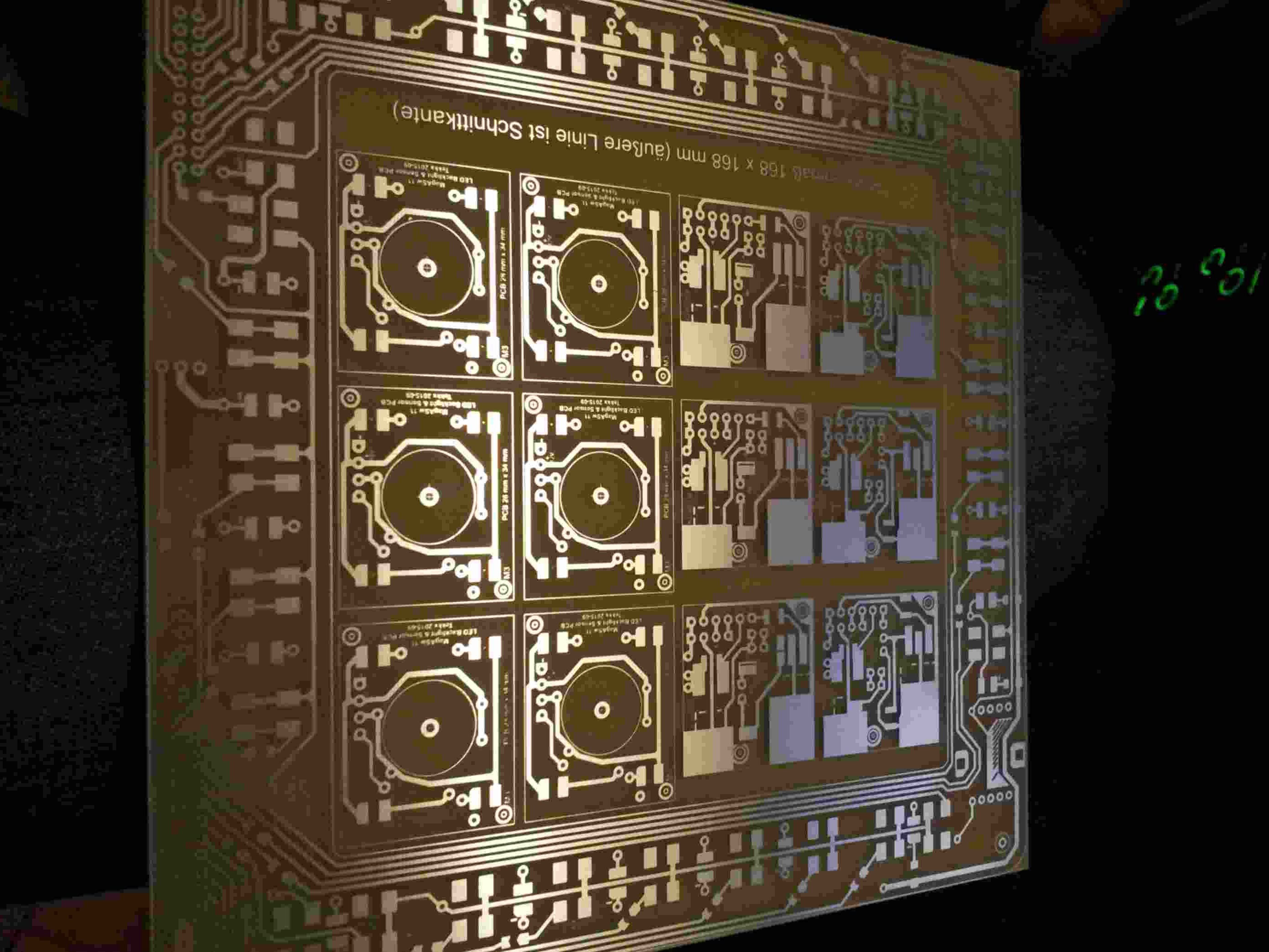
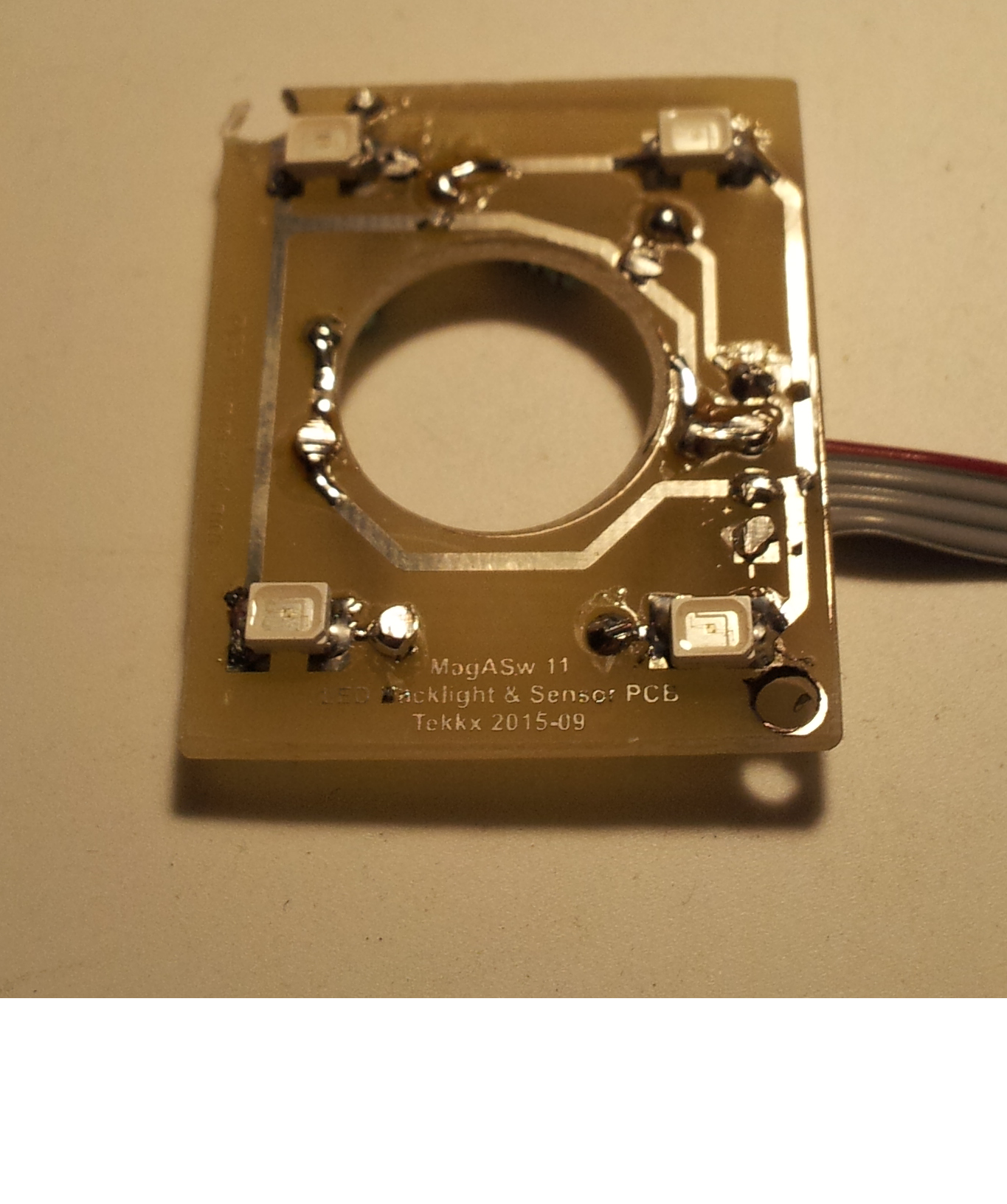
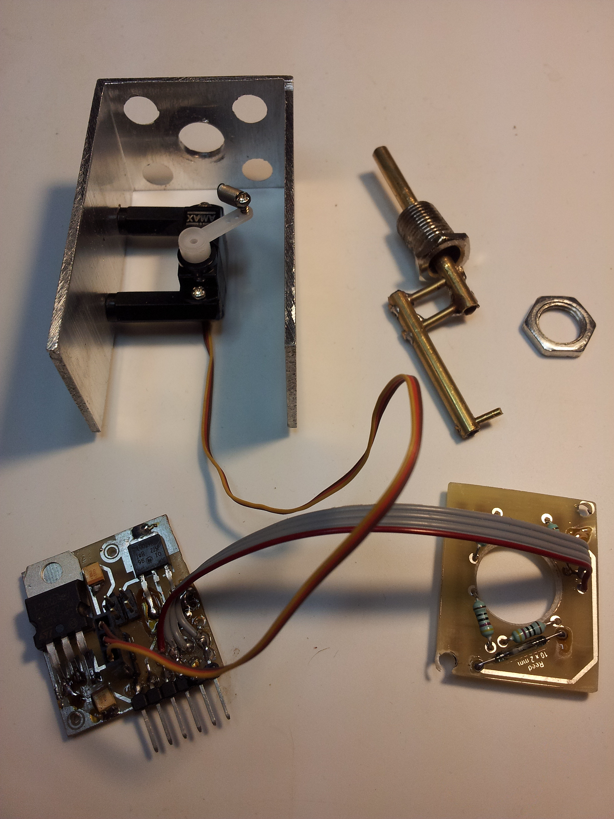
Yesterday the brandnew PCB delivered. Right now I have no time to saw and solder them. Status of our project is attached ;) Look at the Pics... I may need new glasses. Tho' it works I'm not in danger to win an award for beauty. In the center of the Control- and PWM-PCB are 4 Pins to be seen (last pic). These are PWM Slave-OUTs (or INs). So there is just one (1) MOS-FET needed if other MagicSwitches (or other Backlights) present and to be lighted. But: I'm still on it :) Right now I have to spit some code and make a first test run.... maybe tomorrow :music_whistling:

-
So meanwhile we should buy some RS-485-Tranceivers like this? (0,20 Euro pp) This would be a tremendous relief to the USB. I keep my fingers crossed :)
-
Without knowing much about resolution and this all mattters: I made good experiences with a X52 (not pro). But: The X55 is quite better. It is more like the A10 Stick and Throttle. I use the smallest Spring with cropped a half winding. After some mess with axis curves it works really good.
-
That's a really good hack. (Watched the vid) I allready did some tests with servo connected to arduino instead of servo tester: Conclusion is I came up (depending of kind of servo) with an angle of exactly 120 degs with the Servo of my choice. 120 is the magic angle. And this is a lucky matter!!!! I try to imagine to hack this micro-servo. I would need a clean room and a mid class microscope :) My tax-case is almost solved (means: sent to the gov after a few days w/o sleep) so I can do further tests and tinkering next days :D Also I cleaned up my cabinet* some. So there is also some place for this ;) * Cabinet: A special room with computers, some kind of workshop, an ash-tray and my pilot's place.
-
Last post here is almost half a year old. I'll place my question anyway: I intend to complete my HELIOS-dash with some rotarys on HSI, Altimeter... Thanks to DCS BIOS this shouldn't become a big deal. Now I am spoilt for choice what kind of rotary. There are so many offers that my hair became grey :) First criterion is size. OK. This is easy. But: - what means "absolute" or "incremental" - which resolution should it be: 20 PPR (pulses per rotation?) or 4000 - there are also "channels" and "detents" Please share your experiences with me. I'm driving crazy!!! I found some at eby with 18 PPR. Should that work? Thank you so much.
-
 Hey Aries. Don't know if you still there... I have FTNIR 1.8 alpha running and use PointTracker 1.1 (Tracker Source) with a home made 3-IRLED-clip. Besides I still have to mess with curves - which interferes between FTNIR and DCS - it runs very stable and reliable. I set a good reachable key (in Options - Keyboard and Mouse Shortcuts) to Center it while flying cause after streching exercises Zero-Point changes everytime. Would appreciate if someone could share his experiences with curves.
 -
I've got the brandnew FTNIR 1.8 alpha today. Many THX to Wim and friends :cheer3nc: I haven't had assumed that there will be some headroom for improvement: This is a great masterpiece of some Software. A pitty, I already told I love it. So I can't augment my commendation ;) @Symphony: Do you use ATI? Read "Known Issues" of FTNIR
-
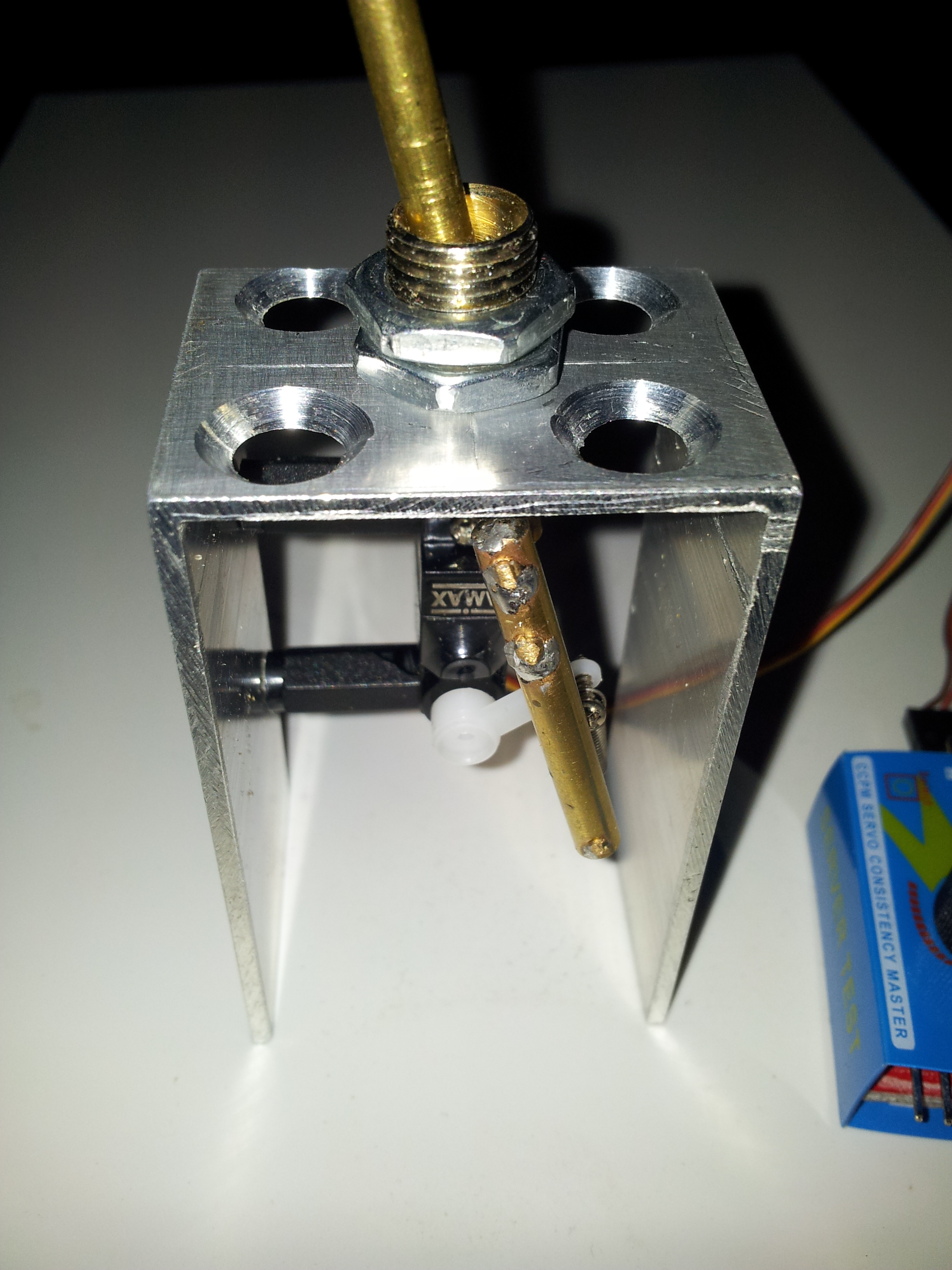
Short update Hello friends. I'm still alive. Work on switch is on progress, due to extern influences just on idle throttle :( I've got a very small and cute servo (third shot). It has sufficient power, acts very quick and fits to our limitations of place. And it was less than 6 Euros (w/o shipping). I think - based on actual data - I can start bringing the parts together in two weeks (means end of Oct 2015). One little problem is there: Vendors of such equipment (below 100 Euros per device) are very stingy with data. Datasheets aren't available. All three of purchased Servos have a moving angel of about 90 degrees (45 in each direction). This is a little bit tight to our matter, should work, but 100° to 120° would be perfect to reach the "snap point" secure and reliable (I keep tracking the FAA-License). ;) I use a Servo Tester device to move the Servo. I have no idea, if the moving range is limited by the Tester or by the Servo itself. As you may know, I am a dipshit in programming. Also I have no idea to simulate the right PWM-signal to check out, what the servo is really able to. So: Is there someone who can provide some code for an Arduino (I have several on hand)? One button to move full in one direction at maximum speed, one button to move reverse at full speed. That's all. Do not integrate it to DCS-BIOS, so I can make tests w/o other tinkering. Later this code would be the base for final MagASwitch related DCS-BIOS code. (Don't want involve Ian too much with this. He has to graduate in a manner to become our pride and joy) :) That's for the day. Ready for further talk on. :poster_offtopic: PS: While doing some tests with headtracking I loose more than 3 planes. I hope, my insurance comes up for this :joystick: And - you will already know - another Edit (one day later): It seems that I am some dopy: There is a ready-to-use servo library for Arduino... That should work for me to test my installation in about two weeks.
-
rgr. Will try this. One BIG drawback came with IR-Clip: A hot tip of a cigar is recognized as a 4th point. 4 points = BAD. :cry_2: Edit: After the trick with Scotch Tape doesn't work really good, I took some fine grinding paper and roughen the surface of LEDs. Now I can yaw my head almost 80 deg (there is no monitor at all) in both directions without loosing track. Second Edit: Sent a small donation to Wim (Dev. of FTNIR)
-
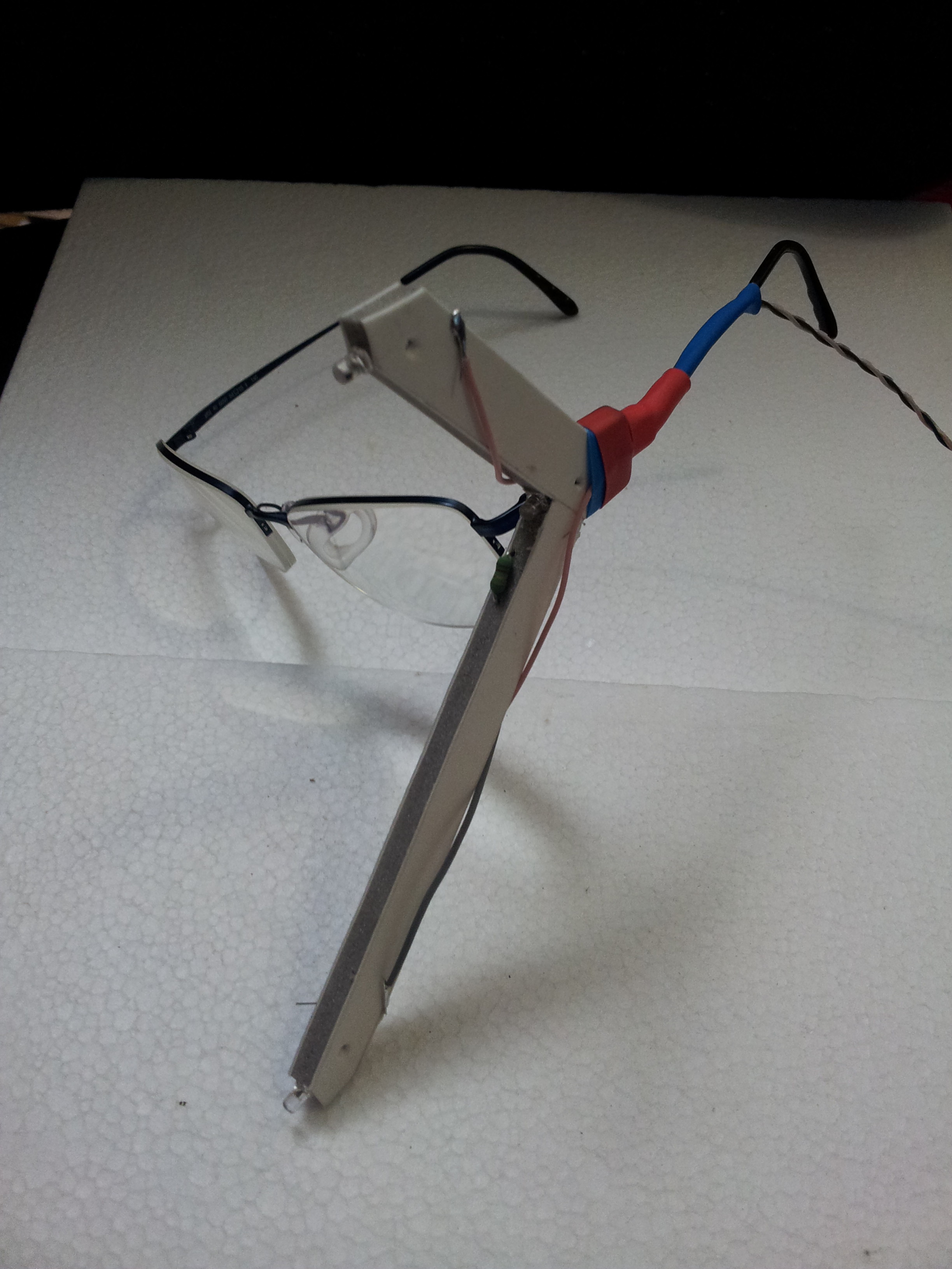
I made some experiences with FaceTrackNoIR and Freetrack. Facetrack looses track under weak lighting while moving fast. Also it jitters around so I lost about 3 planes :music_whistling: Freetrack I didn't brought to run. Meanwhile - trying different cameras - I've ended with a PS3 EyeCam (7 Euro at eBay + 2,99 Dollars for the driver). I use FaceTrackNoIR 1.7 Settings: as TrackerSource PointTracker 1.0 as Game protocol FreeTrack 2.0 Today I nailed a Clip of Hard Foam with 3 3mm-IR-LEDs and put it on the frame of my "Gaming Glasses" :) The LEDs in series with a 16 Ohm resistor, fired with 5 Volts. (right now from a mains-adapter, later out of USB) Now it works fine. If I add some kind of diffusor to the LEDs (right now no idea what to use for - some kind of translucent balls) it should work perfect. Right now it looses track if I turn (yaw and pitch) too far. This is caused by relatively small emitting angel of LEDs. I have still to make some tuning with filters, curves and other Settings. Time will come :) Now I have TrackIR what I spent 15 Euros overall for. Think I will Support FT-Team. :)
-
What happens if you connect other ground pin at arduino? Same? Or try to ground poti's housing. Smells like some interference with sth. like PWM or sth else. Just theory! :)
-
Hello, dear community. Since I encountered the same problem today, I wonder if there is a solution in sight. Meanwhile. The Story: Cause of facetrack-caused problems I saw no other way out to test a triple-head installation today. To fire 3 montors with 4864 x 1080 pixels seems not to be a problem to 2 GTX580s. I edited *monitor*.lua and it works. Some blurred, but this is subject to diskuss at other place :) (meanwhile solved: forgot to change ratio in LUA). The Problem: After I added a 18" for some gauges by HELIOS (incl 2x MFD and RWR) and a 7" for CDU-screen, DCS A10C now is completely unplayable. Framerate is felt by less than 10 frames per second. IF I could export Gauges, MFDs and CDU to another PC (there is a dusty one with good GPU available) the problem would be solved. Maybe. HELIOS export to a second PC should run fine (not tested yet, I confide 100% in Gadroc's good work). But how to export MFDs, RWR and CDU to a second PC (TCP preferred)?
-
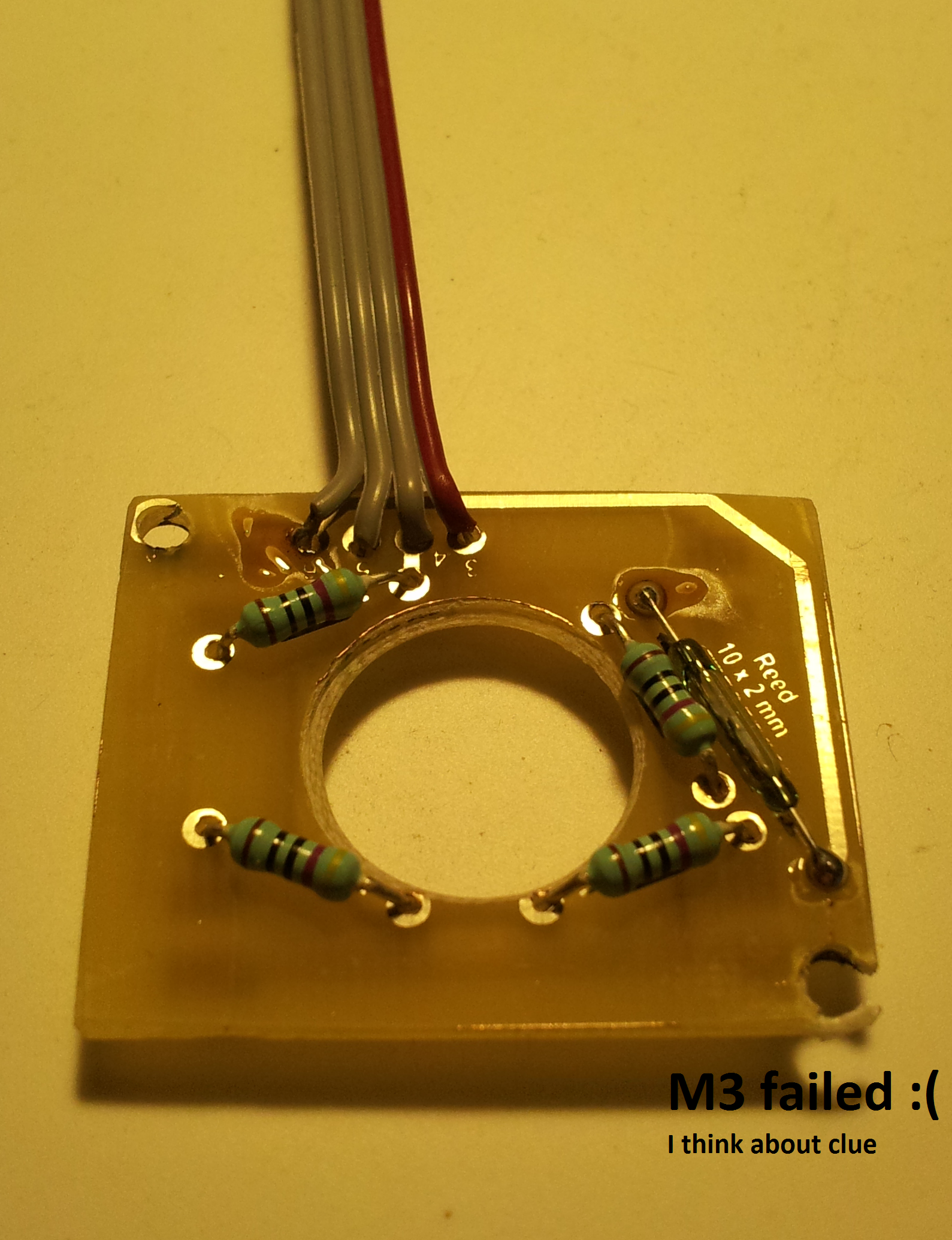
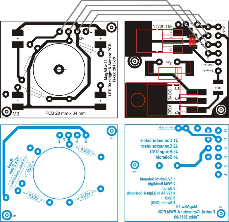
BTW: Here are my PCBs Left is on top with 4 LEDs and Reed-Switch (instead of the micro-switch) Right is the Control- and Amplifier-Board with MOSFET for LEDs and Darlington for Solenoid Black is Top-Layer Blue is Back-Layer (that's why as mirror) Red are the devices. Update one day later: Purchased two different Servos (at a bargain price) and a Servotester (to activate Servo w/o running DCS) Top PCB (LED backlight and Reed Contact) isn't obsolete. Control PCB is to overhaul because we'll need 5 to 7 Volts to drive the servo. If the stuff is on my hand I'll do a prototype, controlled by this Servo-Tester, and we'll see :) Another important Update: If someone has the intention to follow this way (with solenoid): Note the updated PCBs: Between Base of Darlington and Control Input (Output of Arduino) a 10k ... 100k Resistor has to be included. Otherwise you get full 12Vs here. Consequences aren't subject to explain ;) I already killed my brandnew Servotester, also by unobjective mixing of 2 testing situations (means: stupidity). It was just 2,50 Euro. Cheap lesson :music_whistling:
-
Thank You, Ian, to prop me up ;) Your recommendation to use a servo is agreeable. Maybe I find one in one of my junk boxes (did some RC experiments in the 90s. Stupidly I purchased a stack of solenoids just today :doh: and I found a neat solution to fire the solenoid by Darlington. If the "Servo-Project" runs fine, I can still resell them. That's real spirit of research: You have to be able to reboot your project. :) I have sufficient Alu-Profile and other stuff on hand. So I can screw sth. together. I'll report if I'm ready for further talk on. Brake a Leg!
-
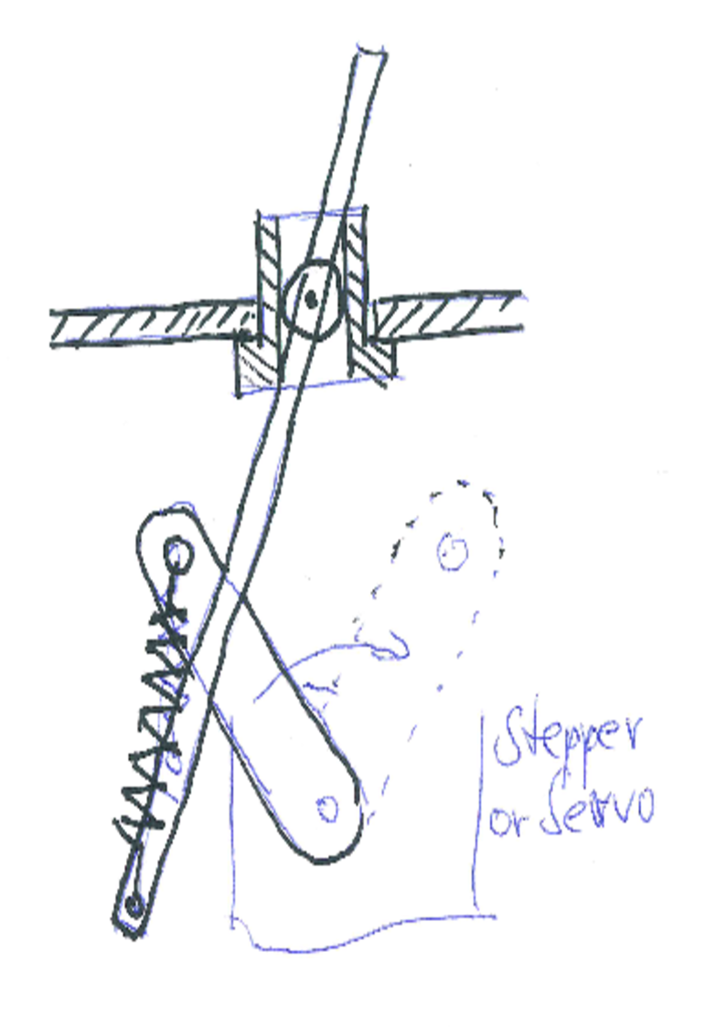
Hello, dear Community. While I did (due to lack of time) very small progress (not none) in fullfilling my order I followed the steps in adapting stepper motors in DCS-BIOS. The Boys are doing great work there: http://forums.eagle.ru/showthread.php?t=141095&page=12 This great work inspired me (as all of those action) to make some thinking about options regarding Mag Actuated Switch: Maybe a stepper solves the problem of heating treatment and weak forces. The stepper moves - instead of the lever directly - a second lever and alters AoA between Spring and (Main-)lever. Servo's Lever and Switch's Lever are just linked by the Spring. So you have - if switch is manually actuated - not to act against the stepper. Attached is a quick made sketch of my thoughts. I am at work right now :) Note: NO scale! No Switch yet! Principle: A spring holds the lever in its position and pulls it back if lever is actuated under "cold" condition. Remote Actuation: In case switched device (EAC e.g.) spools up, stepper moves in pos B (right), spring moves over a snap-point (or whatever the term is) and lever jumps to ON position and is now held there by the spring. Manual Actuation: Lever is to push against the Spring and activate Micro-Switch or Reed-Contact (latest concept). Activated Device (EAC e.g.) spools up, DCS-BIOS sends corresponding signal to Servo. Servo moves secondary lever into B. Main Lever stays in ON position. Similar in reverse action. Terms: First: Stepper has to move quick. Second: Stepper has to be strong enough to act against spring's force. Advantages of this solution: First: There is no solenoid which could overheat while holding switch in ON position. Stepper has to work just a few milliseconds. There is NO current in terminal positions. Second: Force of Spring could be chosen relatively strong, depending of stepper's size and AoA. Drawbacks are: First: Ian has to write special code (or has to modify it) Second: We would need a driver board, cause I don't think, Arduino can feed such a strong stepper on its own. Third: Almost all I've done till now is scrap. Fourth: I have no adequate hardware on hand to do some testing.
-
This is exactly what I've been thinking. (Without knowing so much about coding) But this doesn't affect Ians and Gadrocs great work. Thank you. Acceleration could become interesting, if someone build a "moving" Cockpit. Like real Sims does. There are great masses to move (some of us more, other less ;) ). So don't Shift-Delete your code. :)
-
You made an inviting offer. I do all my sketches at CorelDRAW! cause I can and have nothing else. I took in early 90s some AutoCAD R14 lessons, but due to absent working and licensed copy I forgot how to do with :( So my sketches (at the end drawing-like) all in good old 2D, called "senkrechte Zweitafelprojektion". I have no idea how's the english expression. I have - if needed - three different looks (front - side - top). (If someone knows the english term: PM me. So I will improve this post) For flat objects works CorelDRAW! very well. My PCBs I gave as *.tif to the etching man www.platinenbelichter.de. Laser cutting of Acrylic Panels I sent as *.svg to Formulor.de Cutting of Cover-Film and Text I sent also as *.svg to a local advertising agency. (All links are only interesting to the german freaks. Sorry.) Why I tell that? Due to lack of experiences I'll need - if the time comes - instructions in which way I drop the data for further handling and adaptation. Update: Yesterday I overhauled lever-bushing-assembly (I love it), did the Backlighting-PCB (looks good) and caught an exhortation by my wife: "... is there nothing more important do do?????..." She's right. There is still this Tax-Matter. (Long lives Procrastination!)
-
Thank you all. I'm so happy to have got your appreciation. Stay tuned for the next steps (even those will delayed, because some real life really exists - instead there is the matrix at all). Meanwhile I have the DEVICE completely disassembled increased lever's travel angel for some degrees (with still unknown side effects) made a parts list (not closed yet) planned arrangement of 4 LEDs and 2 PCBc did some general dreaming Next steps are layout of PCBs crafting two studs redesigning pivot points reassembling disassembling make drawings
-
Thank You, Warhog, for your kind comment. But my intention isn't to build a cockpit. I have neither place nor time/money to do it :( I found just a problem and the urge to solve it :) It's just a gift (or let's say: return) to the community. Otherwise, since I've detected facetrack (works likely well) and with this side panels are almost impossible to klick to, it seems I have no other choice to build SOME LIKE a cockpit. So, maybe, I use the prototype for building a LASTE panel.
-
That's it, my friends. :) Still with no electronics - just a simple self-hold-circuit with a push button to simulate Remote-ON. Now I have to remake all parts in a craftsman-like manner and reassemble whole shit. Than I will share - if you want - some drawings and parts lists (even with prices). I know, during next 2 or 5 months I won't become a famous Videomaker (this is my first attempt - and maybe the last ;) ) My wife is a professional at those things (with diploma) .... but I won't involve her too much... :) By the way: I have changed project's name from Magnetic HOLD.. to Magnetic ACTUATED Switch :) syaw7o3idp8
-
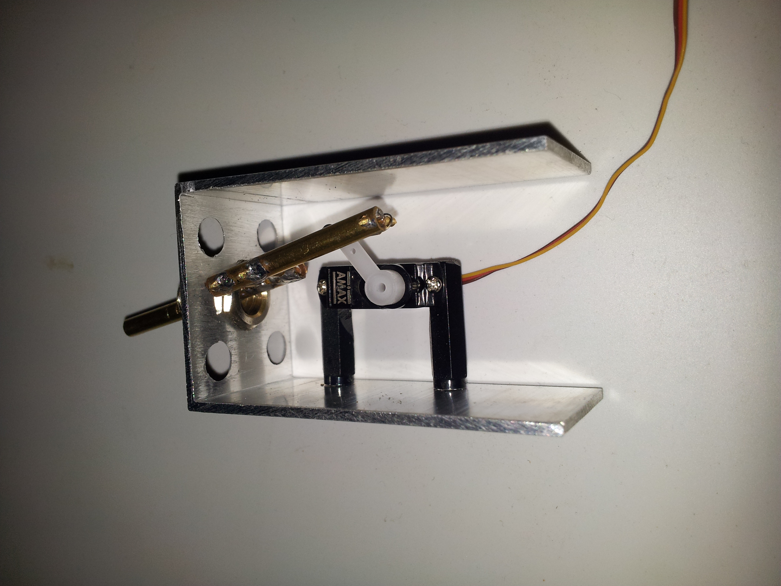
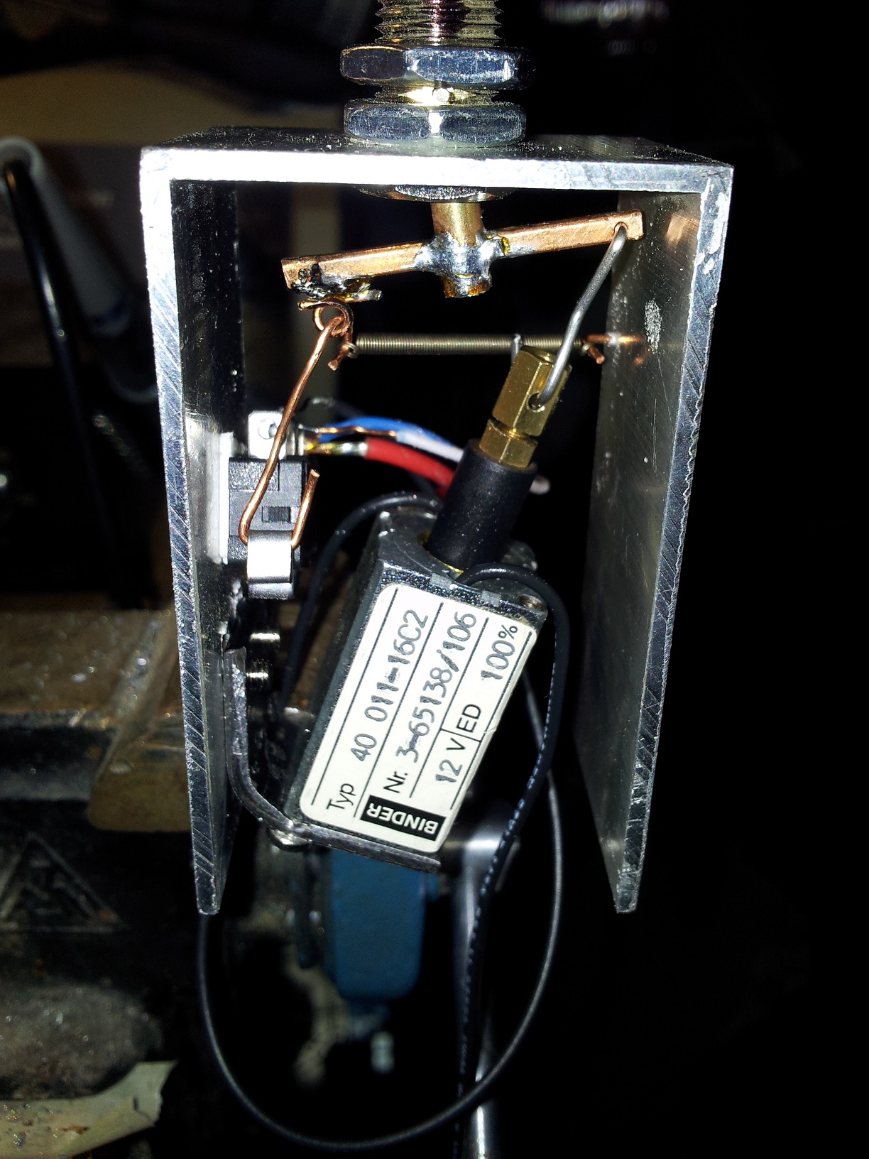
First Tests success (with some faults) Heureka. I did a first prototype. (still without any electronics) We won't get a FAA-licence for it, but it works. Technically. Look at the pics. Both pics are token at OFF-Position. Don't mess with my wireing. I couldn't await to see it working so I took what lies arround :) What I have learned: I need a bigger Solder Iron and a middle sized box of 1-mm-Drill-Bits ;) It (the lever) is a little bit untensioned cause of unsufficient power. From READY-Condition*, lever is to push in ON position without almost any resistance. But it flies with a KLICK in ON position if it's powered by remote. I had to make some agreements due to DC (duty cycle) of solenoid (heat). Right now it becomes just about 35 °C. As I assumed earlier, balancing of lever length, spring tension, travel ranges and AoA of all involved forces is the key :) Thats why the solenoid is off vertical alignment. Maybe tomorrow I'll take a video while working. (New wires and some kind of test bed is to do before). * READY-Condition means OFF position with 12V present, but circuit not closed yet (will be closed if lever pushed manually in ON position)
-
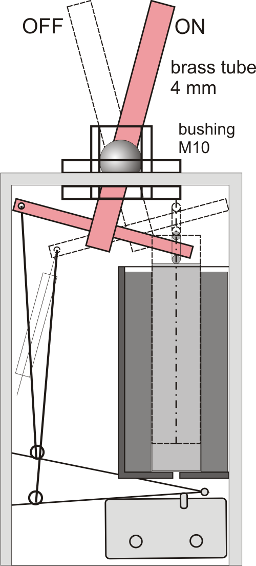
Coil + MOSFET = sudden death!!! I knew this before :) Inside the housing will be enough space for any electronics, as MOSFET, Diode, Resistors for Backlighting. At the End you have to feed it with 12V DC (used for Solenoid and also Backlighting), 5V logic for ON, PWM 5V logic for Backlighting (I mean, this is the most usable way to dim backlight) Also there will be GND Output ON + his own GND (for Matrixes) Six Pins. Thats all :). Good idea will be to add a second linked socket to connect up to four switches (a simple kind of bus for clear layout of wires). --------------------------------------------------- Viperpit are a closed Community. Even reading is just for members. Not sure, if I should support this... I am a open source fan ;) Meanwhile I have a new design with a vertically mounted solenoid. Much more space for copper and core and much more easy to fabricate and mount. Let me bring it together and we'll see..... :) Picture is just a preview. Edit: Yesterday I mounted a model, just consisting of housing, bushing and lever (looks like a hammer). Spring was simulated by a rubber band. Works very well. I'm confidentially I can bring it to work. Main problem (technically the only remaining one) is balancing all involved forces. So further tinkering is focused on gadgeds for finetuning and shifting the whole "Klapparatismus" (there is no english expression for that mechanically assembly) ;)
-
Thank You, Hans. This video brings the last missing answers. Cool. I think, now I can bring it home. Stupidly I am heavy involved in other matters (declaration of income, e.g.) so my next steps will be some delayed. What I already done: Lever is set into the bushing (works well) Housing is ready (looks good) I'm on checking different options to limit current (or voltage - outcome is almost the same) after switch has reached ON-Position (we mustn't lose the focus on costs of a single item, so I try to keep it simple) and "everyone" should be able (if he can handle a screwdriver and a metal saw) to remake it at home. If the copper is delivered I start learning to make solenoids (bigger is better is what I know right now) Another milestone will be dimensioning and fabricating of the retention spring. It should have the right force and it has to act linear or degressive!!! (by the right angel of attack). I also thought about a plus option: I'll add 2 or 4 green LEDs on Top for panel's backlighting. Dimensions of housing will take some place. So you have just to make a Front Plate from a translucent acrylic material, glue black film with cut lettering. Ready. That's today's update. :)