Tekkx
-
Posts
319 -
Joined
-
Last visited
Content Type
Profiles
Forums
Events
Everything posted by Tekkx
-
@all not got an email ;): I'm at a very early stage becoming familiar with TFTs. I would risc a close look at the MCUFRIEND_kbv.h There is at line 28 (inside class MCUFRIEND_kbv) (and there is also a command to flip the whole screen):) I assume coordinates depend on screen's size (resolution), color should be something between 0 and 65k... How to call this in the *.ino I'll find out if my screen arrives from china :) Maybe it is documented somewhere. PS: I understand this Forum as a platform where we discuss problems or affords and Share this with each other. [emoji8]
-
... as I told. :megalol:
-
Some Day you will add some legs and wings to your pit and go on excursion over the Outback :D
-
No. Hansangb. I mean, it's to protect button's bottom from paint while painting (spray e.g.). After paint is dryed peel the film off and there is a clean inlet for the light (from the rear). For glueing the layers you HAVE to remove the film where the adherends are :)
-
RK, I love your pit, your way to solve problems and I thank you so much for let us peep behind the scenes :) So I want to add my personal share to this: I glued all my CDU-Buttons row-by-row on stripes of thin transparent film (as used for sales packaging - here called blisters). This brings three benefits: It prevents the buttons from falling to the floor (and jumping into unreachable corners), prevents the round buttons from spinning and not least makes mounting the panel much easier. Glueing them together is not a problem due to the very little stroke of the momentary SMD-buttons. So actuating one button doesn't affect its neighbors. Maybe this helps others. While tinkering my next panel (just IF I do) I will combine both methods :) Thank you.
-

Get no Emails on new Posts in subscribed Threads
Tekkx replied to Tekkx's topic in Forum and Site Issues
Of course. You are right. I'll amend this in my posts. :music_whistling: -
Get no Emails on new Posts in subscribed Threads
Tekkx replied to Tekkx's topic in Forum and Site Issues
Dear QuiGon (and others). Oh, yes. I checked that uncounted times (not just "double check") :) To prevent any missunderstanding: 1und1.de works strato.de don't! Looking forward to hear about your experiences. PS: I got notification of your post just in time. (as expected cause I use my alternative adress hosted by 1und1.de ATM) -
Get no Emails on new Posts in subscribed Threads
Tekkx replied to Tekkx's topic in Forum and Site Issues
Problem is located somewhere deeper Latest news in this "Notifications Issue": As I wrote above, I changed my registered email to another ISP (edit: I mean Web- and Mail-Hoster) and everything worked fine. Now I canged it back to he original one (was some confusing to get notes from the forum to my business account :)) After changing appeared same behavior as before: No notifications and (even more important) no verification email. That means: "You not may post... (anything)". After a passionated dialog (very close to harsh language) with my ISP (amendment: Mail- and Web-Hoster) came out, forums.eagle.ru may be on some like a Blacklist. I wrote some what of "... capacitation ... they wrote: " ... nope ..." and "... we're happy if we can solve this with your help..." Means: Right now I'm doing theire work. Shame. Dear readers of this post/thread: Is there someone with same or similar issues? I live in Germany (not my own decission) and my (not working) Mail-Hoster (amended) is strato.de. The working one is 1und1.de. Please share your experiences. If there is an Admin reading: Came there some kind of so called "Bounce Mails" in? I could send a copy of this dialogue, but it's written in german... Tell me, if you interested anyway. Please help me (or I will steamroll a little cute dog - your fault!) :closedeyes: -
Get no Emails on new Posts in subscribed Threads
Tekkx replied to Tekkx's topic in Forum and Site Issues
I solved it meanwhile :) Found a post somewhere in this forum that described a similar problem (Sorry. I don't remember the issue). Changed my e-mail adress. Lucky to have more than one of them :) Not changed it back yet. Will see, what'll happens than. -
This looks like a really big step forward :) I bookmarked this Thread in case I rebuild my own CDU. (Was my very first project for DCS and I used each option to fail. Learned alot hereby) Thank you for thinking, making and (not least) sharing :) You are some of my heroes!
-
Hallo Dears. Yesterday I stumbled into Nextion HMI (Human Media Interface) Screens. It's not my problem right now and not at high priority to me. But: Could this become a "short" way to a new kind of CDU-Screen without messing with Monitor-Export and VGA-Converter issues? I post it here cause making controller modules without DCS-BIOS doesn't make sense to me. The other way round: DCS-BIOS with RS-485 opened a countless amount of doors for pit-builders. :)
-
Opentrack track clip with fixed ir led
Tekkx replied to aap_flanker's topic in PC Hardware and Related Software
@wormeaten: Looks very interesting. :) This is an outstanding example for: improvised things are the most sustaining things :) I have a lot of such steam punks here. It's a big benefit for simmers (in contrast to modellers): We do not have to make our stuff for the showroom ;) What kind of LEDs you are using? -
Opentrack track clip with fixed ir led
Tekkx replied to aap_flanker's topic in PC Hardware and Related Software
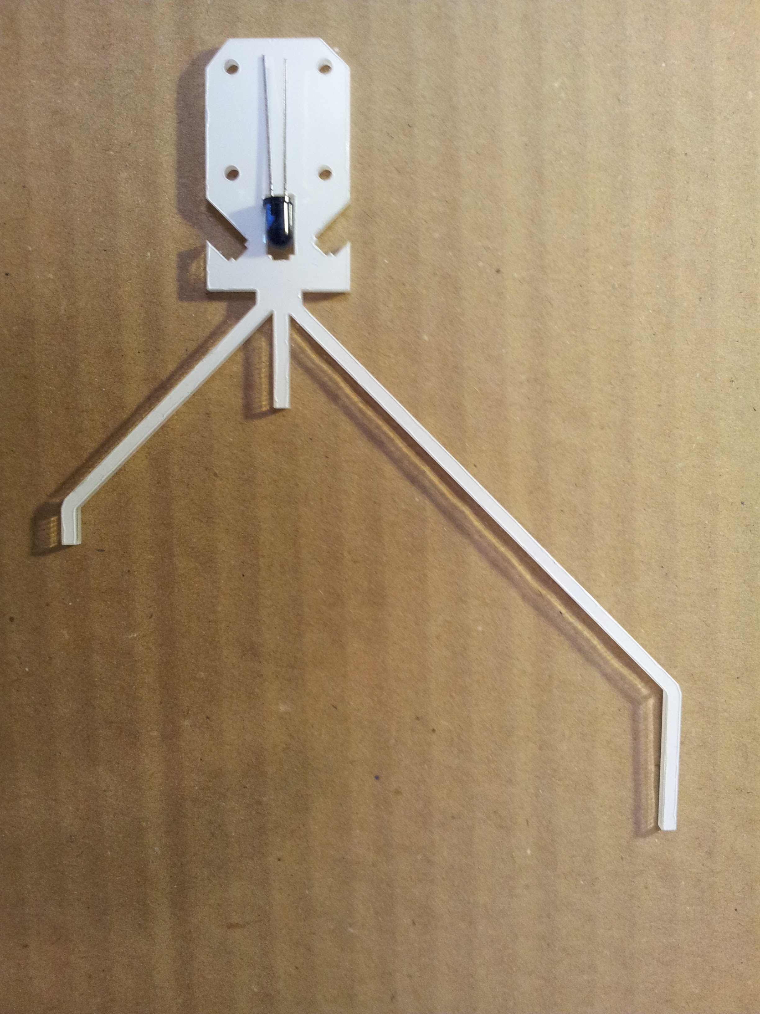
Maybe it solves some problems if you shorten or extend your upper or lower "arm". So they can't shadow the middle LED. But if they too short, your head comes in the line as you turn it left. Let a friend take some photographs of you (sidelong, best while dogfighting) at different positions of your head/body. So you can determine the extreme nick angels and LED's positions (length of arms).. ( just an idea of this minute). Don't forget to adapt your settings in Freetrack or FTNIR every time you made a modification. I will remake mine also. But it's just one of my (felt) 1023 DCS-related projects, so it stuck at a very early testbed-status :) The pic shows an attempt I did very quick as I gave an order to a laser cutter's studio. There was some unused place on the sheet and so I "quick-drawed" this and put the thing there. The design is completely unscientific and has some headroom for improvement :) It is cut from 3mm clear Acrylic sheet (white protective film is still on it). It works as a light conductor. Three IR-LEDs will shine through the arms. I don't know if it'll work. One LED I put there for your imagination :) Maybe I bring some silver coating on it for better reflection inside... (???) As I see as I previewed this post: Photo is token upside down (Australian way). :D If someone has a laser cutter on hand, I add a link to a SVG so you can do your own tests :)
-
Opentrack track clip with fixed ir led
Tekkx replied to aap_flanker's topic in PC Hardware and Related Software
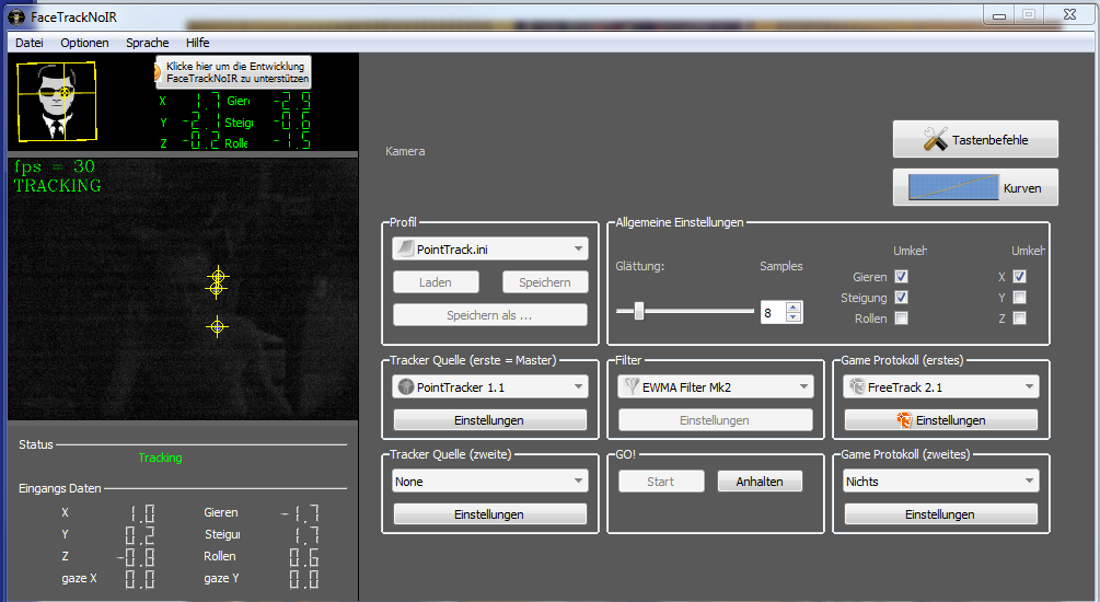
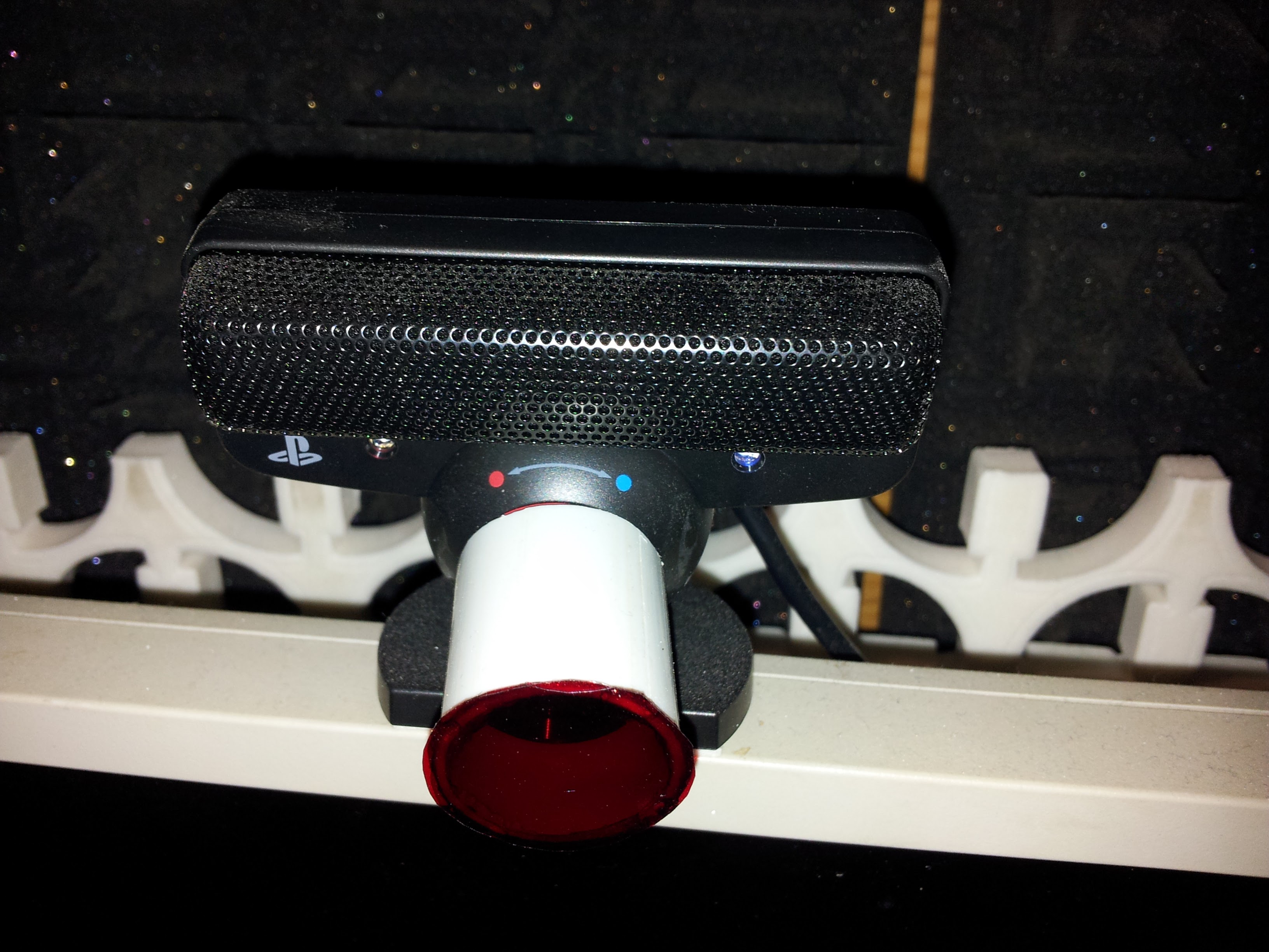
Now I read the opening post completely: I also use the PS3eye (was also cheap at eBay). If someone read this later and want to redo the whole thing: If you use IR-LEDs with enough strength (your - aap_flanker - 5mm ones should be good) it shouldn't be necessary to modify your cam. I just added a simple piece of red film (used for lighting in theaters) in front of the camera to filter unwanted light and side effects. I added some photographs with - clip: you see grinded LED-tops to diffuse theire beams. Clip itsself is made from sandwich card-foam-card as used in Advertising or Architecture modeling. The whole clip is very light-weight. The heavyiest thing is (maybe) the 8.5 Ohms Resistor :) - PS3eye with set red filter - just a piece of 25mm-vinyl tube with glued film - screenshot of FtNIR while tracking
-
Opentrack track clip with fixed ir led
Tekkx replied to aap_flanker's topic in PC Hardware and Related Software
Thow the question isn't directed to me: It depends not just on length of arms ... Most important: You need a clean calibration of your clip (no matter, how it looks like). Main thing is, LEDs mustn't cover each other at some positions. FtNIR has to "see" three LEDs at each time and position. Also (somewhere in FtNIR - now don't remember where) you can determine behavior of your (virtual) position if FtNIR looses track. My tracker looses Track everytime I nick down to look at some Instruments like CDU or AAP or the ashtray... virtual Head (at my configuration) stays where it was until tracking goes on. -
Opentrack track clip with fixed ir led
Tekkx replied to aap_flanker's topic in PC Hardware and Related Software
Thats why I posted it here :) Sometimes (or: over times) it can become some annoying to change specs each time you want to move away from the cockpit. Right now ("now" is relative cause I think about a lot of things) I think about a gimmick for easy removing and replugging the IR-clip. The quest is, to bring that thing with a single move (without seeing anything - it is besides your head) in a very exact determined position (without degrading calibration of FtNIR). Two pairs of very heavy powered Neodyme Magnets could do this Job... (still thinking about). -
Opentrack track clip with fixed ir led
Tekkx replied to aap_flanker's topic in PC Hardware and Related Software
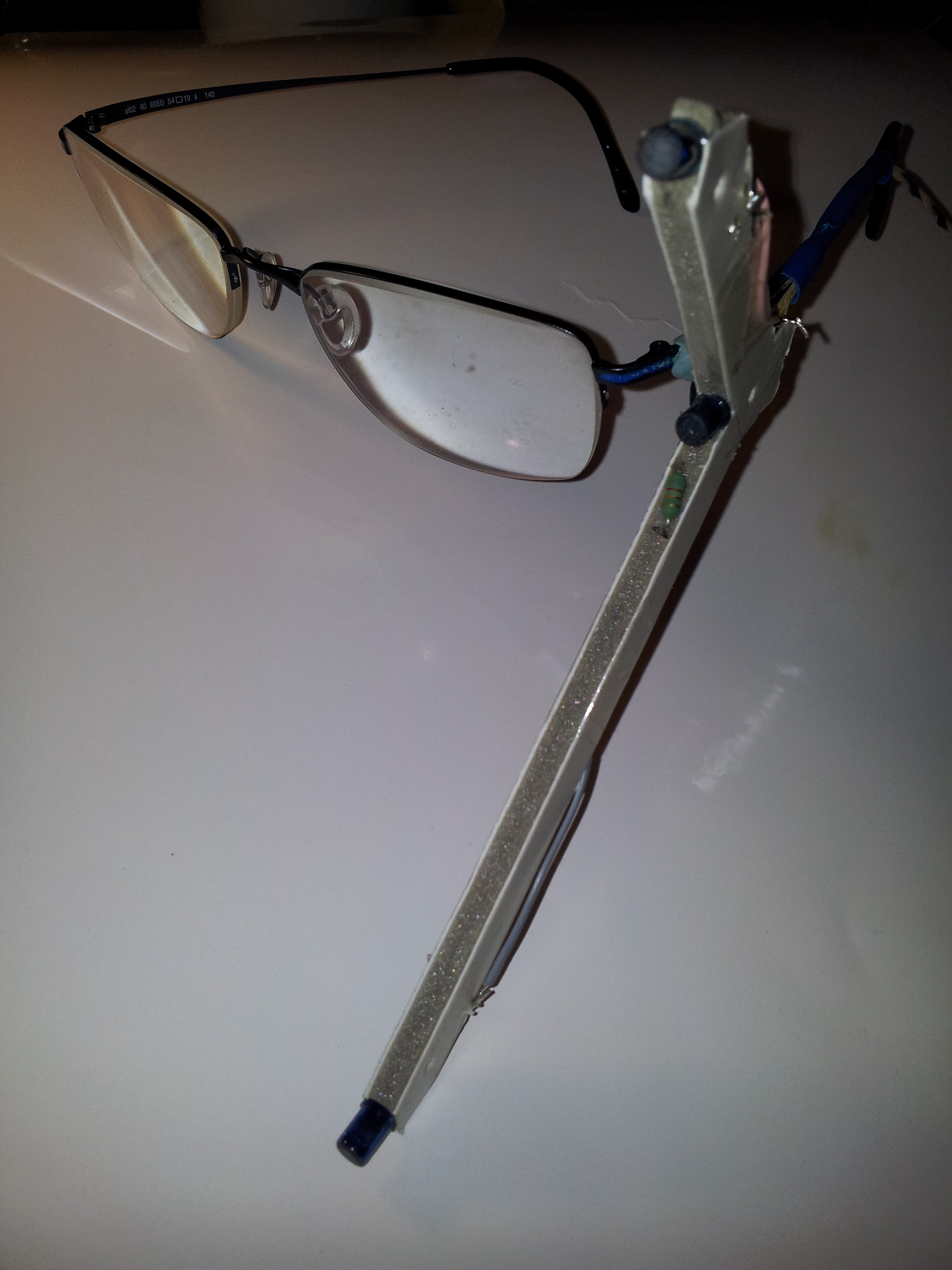
Hey you. I am also wearing glasses. And so my solution looks like this. Some improved meanwhile but almost same. Replaced 3mm IR-LEDs with 5mm IR ones. Works really fine with FaceTrackNoIR :) -
Searching for an volunteer, alfa-testing new DCS-BIOS RS485 transmitters
Tekkx replied to Tekkx's topic in Home Cockpits
Shure. You are right. I solved all my backliting and some notification lamps with MOSFETs. Some 2N7002ET1G (SOT23) up to 300mA for some single or dual PowerLEDs, IRLR024 (DPAK) up to 60A for Backlights. My system has never been very complex and everything was driven by just one circuit.. In therory the coils of my Mag-Switches I want to fire with MOSFET IRF3708 or with Darlington BDX34. Each of these solenoids consumes about 1 Amp. SAS has 4 of them. Continuous. OptoCoupling I plan to positively exclude any kind of side effects. I let meanwhile the smoke out of so many things so I became some kind of scary and look for fail-safe gadgets as good as possible :) One PC357 (simple and cheap Optocoupler) per heavy load appliance is a very small investment. I mean :) Warhog: Are you shure, your MAX485 (not ..487?) are faulty? I encountered also some strange behavior, I trace it back to (hypothesis) unwanted oscillations over the Line with unknown causation. Faked ICs are just one option, fluctuating GND-potential another. (still researching) Results are hot (or cracked) MAX487 and AMS1117. I became quite good in replacing SO8-packages :) -
Searching for an volunteer, alfa-testing new DCS-BIOS RS485 transmitters
Tekkx replied to Tekkx's topic in Home Cockpits
Hallo Warhog. Nice to hear from you. It's a pitty: You would have been an ideal candidate :) But it will be great to mix our experiences. I went for RJ45 due to easy connecting/disconnecting. Thow this isn't relevant if the Pit is ready done :) While the bus has enough power to drive all backlites at a channel (so is my thinking ATM), I havn't solved another problem yet: If there are panels with high current consumption (as my SAS with - still under developement - MagneticHold-Switches will be): How to separate those heavy loads from the bus to connect them to a separate power supply. Just a MOSFET (or a Darlington as I plan to use there to drive the coil) can't do the job. I thought about OptoCouplers (already ordered some) to drive these Darlingtons. At an early state of this project I didn't separate control- and power-circuits. As I am lucky, just at the paper. In Germany you'll have to pay for the FireFighters if they dispatched caused by stupidity :) What is your approach in this matter? Did you also separate the GND of your two PSUs? -
Thank you. I love your detailed explanations. That helps a lot :) Even at own thinking ;) This way I killed about 20 (or even more) Max487 and AMS1117-05: Disconnecting the Arduino from the Transmitter. I'm on adding this Pulldown and also a TVS SM712 to Lines A and B. If I have the first of those boards on hand I'll do a test and will see if there is still something smoking. But this will have to wait until my vacations are over, also the needed items are still at the Celestial Empire ;)
-
@all: Since I was busy and got no notifications for new posts (don't know why) I've been a little stuck (offline) and missed your great progress in adapting DCS-BIOS. Congratulations to you :thumbup: Hope you all are also well at life and health. So I'm a little ashamed about my following (hope: small) question: While testing a small stack of brandnew RS485-Slaves (solder has been still warm) I had something to notice. (See the pic, please) Is this just a "hickup" or should I go against it? My installation consists just of a well working Master and ONE Slave. To the Slave is an Arduino NANO connected with just one button and one LED. Very simple, at a breadboard. No other gimmicks. Linked by 1 m Cat5-Cable. No DCS was running. Thank you for your kind attention. And: Sorry for stumbling in :) PS maybe @Ian: At a german Forum was suggested, to bring a pulldown R (10k) at TXenable Pin. What is your opinion? I think every further load is bad and the Arduino has its own pulldown acitivated (turned on somewhere in your code).
-
Now, with the help of some friends (almost all are users of electronics forums), my family (they gave me some degrees of freedom) and my employer (they gave me not too much load) I managed to bring a first stack of RS485/DCS-BIOS-Devices into life.
-
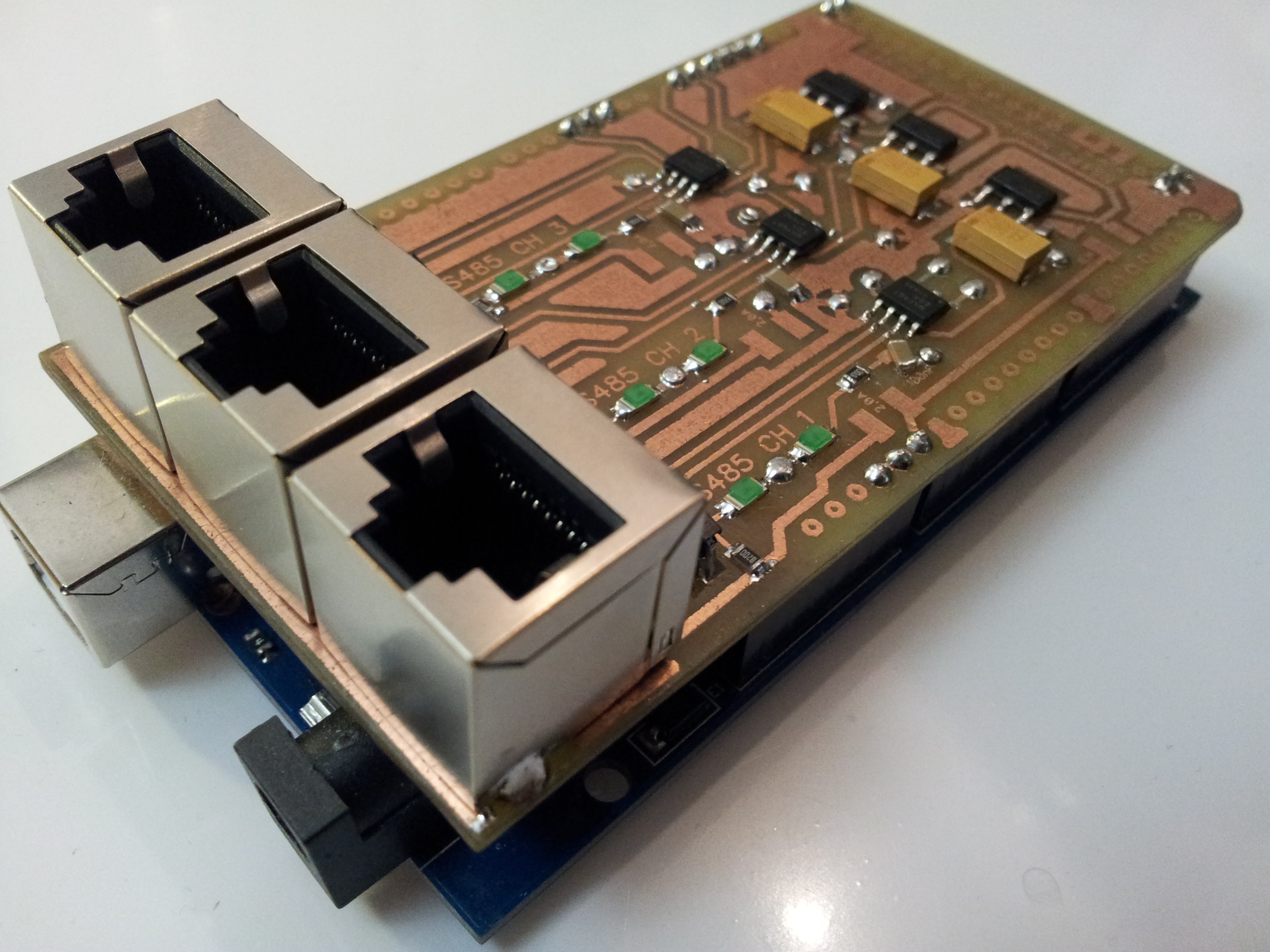
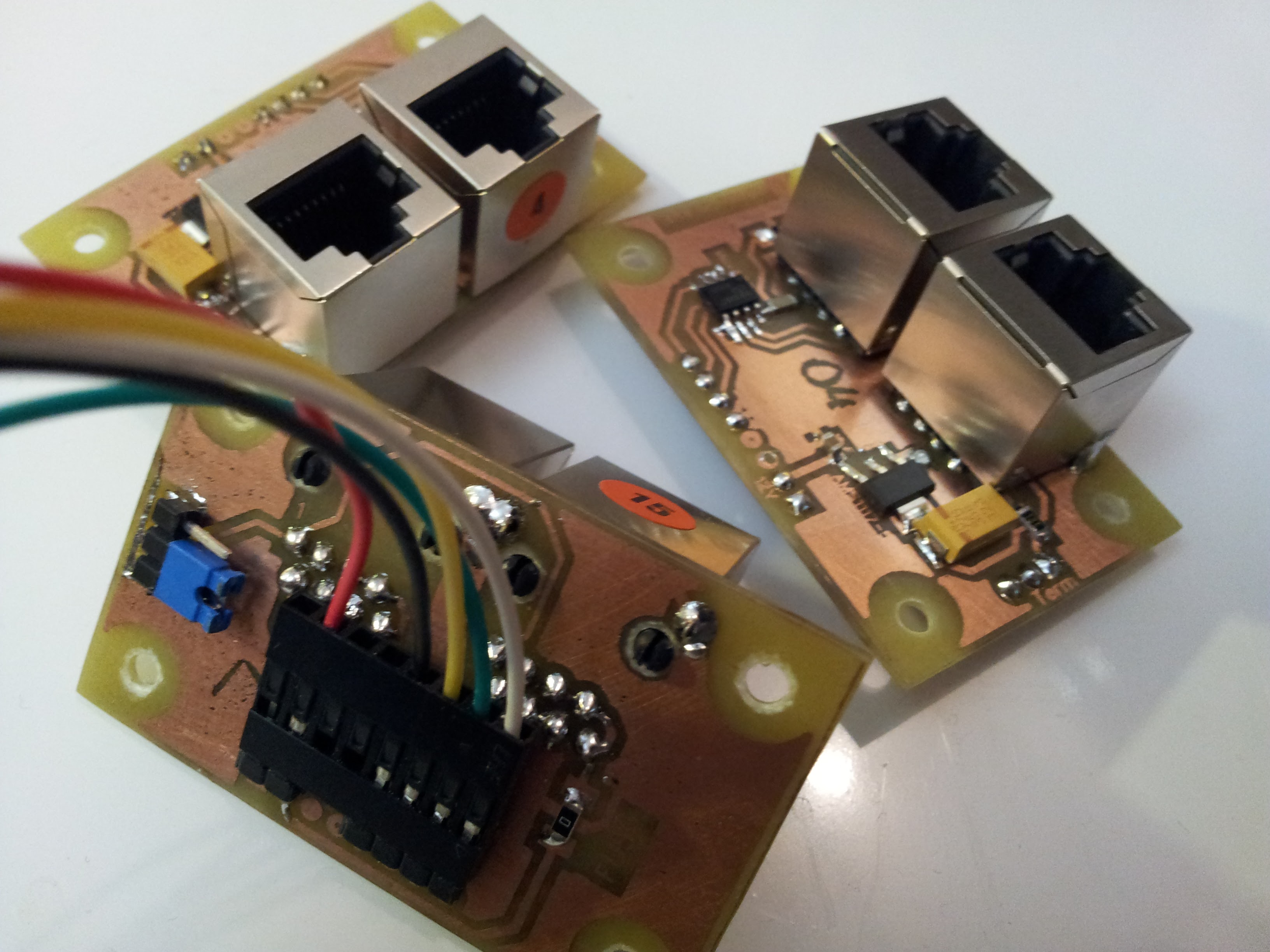
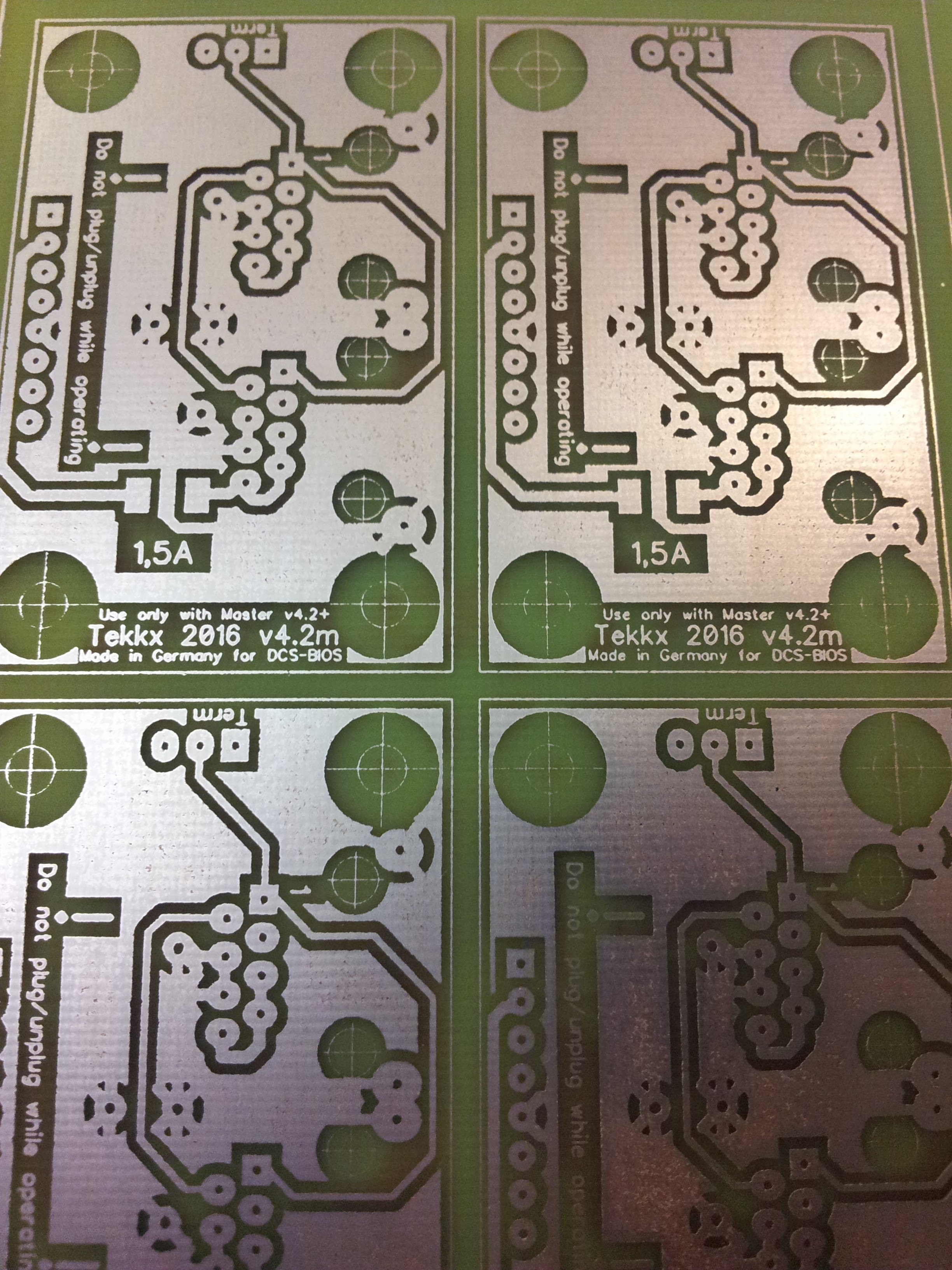
Hallo, dear community. At first: This is not a hoax, joke or some kind of trap or trolling. I promise. It has been a long long way cause I've been distracted by so many other - partially non DCSrelated - incidents. But now is my actual project almost done: I am almost ready to roll out "my" DCS-BIOS Bus-System. ("" cause the software is the great work of [thread=141095]FSF Ian[/thread]) I did some ready-to-run prototypes (really just prototypes as you can see at the pics. Due to I haven't enough panels to connect to, I can't do a significant test. Also is there a massive lack of time for that :( Interested to perform some testing for me and to benefit the community later? Want to be my Mine Dog? The system works that way: Upload the Master sketch to a Arduino MEGA Hook my shield on that MEGA Take some Arduino NANO Upload certain sketches on them Connect them to certain Panels and to one of my (now yours) Slave Modules Link all together by standard Cat5-Cables Plug 12V into the MEGA: Master Module and all Slave Modules incl connected Arduinos are provided with power. System is able to provide up to 1 Amp per Channel (there are 3 of them) Start connect-serial-port.com Start DCS Love it! (I hope so) YOU: - you understand the background of DCS - you know how to write a sketch for Arduino and how to upload it - you understand DCS-BIOS, best: you already use DCS-BIOS - you are a pit-builder and your mashine is running out of USB-Ports - best case: you live somewhere in Europe (even better Germany) - worst case: you live somewhere overseas or Down Under (Freight Costs will kill me - or we have to share those costs) Your flying and fighting skills don't matter. I look for someone who can plug the whole stuff together, give them a sufficient load and can tell me, what sucks. It is important to me, to get those results, so I can implement last changes/improvements and can roll out a first series to the community. And: You have to be cool! 8) I give you one RS485-Master-Shield and (at least) 4 RS485-Slave-Modules to your hands (maybe, I manage to manufact(!) some further more. There are 6 PCBs right now on the work bench waiting for assembling.) For free! As a gift. Really. Not really free, you have to do a little work with them and have to report your results (here or as PM, EMail or whatever). First Pic shows the Master (hooked on a MEGA that I'll keep cause it's my last one atm). Second Pic shows some Slaves. Third Pic shows the next stack under preparation (obsolete meanwhile cause I add some failsafe features just after holidays). You will need: - one Arduino MEGA2560 - some Arduino NANO and same number of DCS-Panels to connect with - one reliable 12V (2 Amps at least, 4 A are better) DC power supply with 5mm plug (standard to Arduino MEGA) - some usual Cat5 Patchcables to connect the whole shit I'm right now on some kind of "manual". If testing is finished you can keep the whole stuff. Next week I have to go to some holidays. Would be nice, if the items sent out before my departure. I am really curious, if someone will do this.
-
Looks all so beautiful. Even the switches are great stuff. Now I know why there has been silence for such a long time. RK: You are a hero.
-
Thow at my understanding of "solid white" and "opaque white" are the same, I got a picture of what and how you do. (It seems, you are also a good photographer) My active Layout: Switches are mounted on the backplate. Backlight shines thru openings (just behind the markings and signs) in the backplate. LEDs (SMD) are located on a PCB, a few millimeters below backplate. Think, I'll follow your path using 2 x 3mm for the Lightplate. Rework the edges of multi-layer acrylic after engraving is tricky and looks (maybe) poor. BTW: I did a step to decrease costs: As laser cut Aluminium Backplates are very expensive (and there remains a lot of rework deburring them), I gave Kraftplex® a try. It's a german "invention" by Franz Betz. This is made from wood, is very rugged, is to paint with any acrylic paint (even Spray Can) and costs much less than Aluminium. The Laser Cutter gets along with a much more smaller mashine (oh, this expression). Means: A "simple" CO2-Laser will do the Job. First samples are promising. I will also do the housings of this magic stuff. This is an example (the 20% finshed SAS-Panel). Backplate is 1.6mm (imp: 1/16") Kraftplex, Notification-Light (still with fake inlet of copy-paper) is made from 0.8mm (1/32") Kraftplex. Laser-Cut. Cutouts for Backlighting are marginal to be seen. To get a relation: The holes aside of the Lamp are 2.4 mm (later M3 to mount the PCB of the Light from behind) One drawback of Kraftplex®: It isn't water resist. So I don't recommend to build panels for a submarine of it. I still have to give all cutting and engraving jobs away to a local or online Cutter's Shop. Had to decide between a Lathe or a Laser. If you cut your panels of acrylic: Is there a heavy inconvinience to the neighbors? (I am a member of the mid-lower class of the society and live in a multi dwelling unit) :music_whistling: