Tekkx
-
Posts
319 -
Joined
-
Last visited
Content Type
Profiles
Forums
Events
Everything posted by Tekkx
-

No DCS-BIOS export data after latest Update 1.5.5
Tekkx replied to Tekkx's topic in PC Hardware and Related Software
Hallo. It took a while (some other issues to solve) but now it's time to close this Thread: Deactivating --os.setlocale("ISO-8559-1", "numeric") indeed solved it. Thank you again :) Now occurs another problem: There is no time left for flying these days... Real life is a mighty thing. -
No DCS-BIOS export data after latest Update 1.5.5
Tekkx replied to Tekkx's topic in PC Hardware and Related Software
Thank you, Capt_Zeen. If I "translate" this line right (I don't speak LUA very fluent), it states to the unwanted Language-Switching. So the Export-Issue is still unsolved. Will comment this line anyway (tonight - I'm still at work). -
Hallo, dear Community. I searched this forum for similar issues... found nothing. So - maybe - it's my fault: Yesterday I updated DCS to the latest version 1.5.5. After this DCS-BIOS (with RS485) spits no output anymore. (What about HELIOS I didn't test. I wanted just to test my latest RS485-Hardware.) After tweaking arround with socat and export.lua (refreshed even DCS-BIOS and Arduinos libraries) - with no result - I downdated to 1.4.(don't remember last digit - I'm not a book-keeper). Now it works fine again (without further tweaking). Is there another one with same issue? Strange side effect after Update to 1.5.5: DCS fell back into German and plays Music (I switched it intentionally to English and strictly NO Music before) :) Can someone tell me, what I did wrong or what went wrong during update? It looks like an 1.5.5-issue cause after fallback it worked again. BTW: Latest Update looked very nice (as short as I used it). Also new items in Menue could become helpful.
-
Hello, dear community. Today I made my first little steps with a Teensy 3.1. I ordered two of them a few weeks ago. After solving a few starter problems (typical, as I see at this forum) I got that thing into business. I expect some more performance compared to "common" Arduino. Also available "uncounted" I/Os make it very appetizingly :) My hope is to solve a display problem (partially). Just for fun I uploaded a randomly (working on UNO) DCS-BIOS-Slave sketch and got uncounted error messages. So my initial questions are: - Is it possible - to a noob like me - to adopt DCS-BIOS without diving too deep into the libraries? - Will this become a bottomless pit? - Is it worth to give it a try? With respect Tekkx
-
Hello Ian. Thank you for the answer. Yes, you're right. I want to override (just for a few milliseconds) some indicators to conduct pilot's attention. Lamp Test could be a good way while my "invention" is on Revision 0.x.x :) Hacking Lua Files is sth complete different: Hands off! (is applied just to me) But I think you poked me into the right direction. Thank you for that. Stay tuned :) BTW: Congraz to your 1k posts :smartass:
-
Hello everyone. (Damned, my notifications of this thread has been deactivated by some unknown reason...) Right now arrised a new (maybe simple, maybe complicated or unsolvable) problem: I'm on a sophisticated Extra for the RS485-bus (will share it as soon it works) and have this question: Is it in some way possible, to tell the (e.g.) MasterCautionLight remote via the RS485-bus to light up? Means that Signal Light on UFC inside the simulation (how to bring a lamp to glow outside is wellknown meanwhile). If the alarm tune also could be activated... even just for a short moment: second best case. The holy grail would be to send also a remote message to the HUD or CDU. Remote from an external device. I studied the reference and found no point of attack. I am this stupid? Off Topic (not to discuss here): My Teensy has arrived. Will give it a try with the "CDU Display Paradoxon" :) PS (few days later): Opened a new thread for this.
-
LOL
-
Hi Warhog. Thats really funny. YOUR amazing work on your gauges (peeping time to time your gallery) made me thinking of my ExpansionBoard. Your way to split the whole shit to several busses is quiet good. I am 100% with you. My attempt targets to another point: The goal is, that each single module has (at the end) one single connector RS485-IN and one single conn RS485-OUT (maybe additional an external power supply connector, Cat6 get slightly warm above 2 Amps.). So you can remove each module (for what reason ever) separate from the pit (like at the real bird). Some modules (maybe) will become a kind of hungry of Arduino-Power so a single NANO, UNO or MEGA won't do the job. So came my idea to split the bus just inside those modules for feeding another (or even two) Arduino. But the whole module is still connected by mentioned two connectors. HSI could be a candidate for this. You are the expert in making instruments. You will have an idea, how much steppers just the HSI consumes and how much pins these steppers will need. Imagine: you remove just some screws, two (or three) connectors and lift off your compact designed HSI from the pit (for doing some maintenance e.g.) Wouldn't this be great?
-
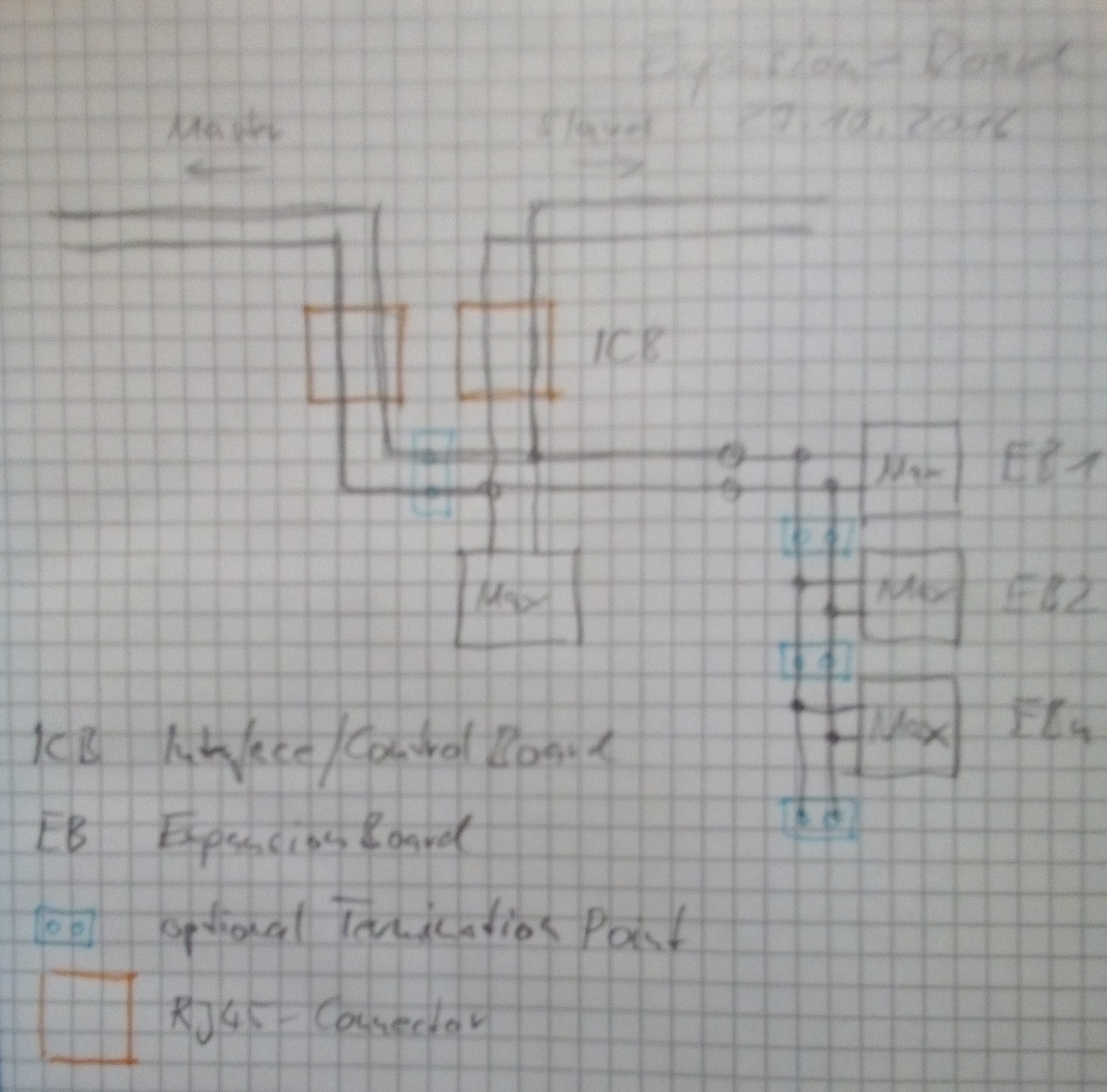
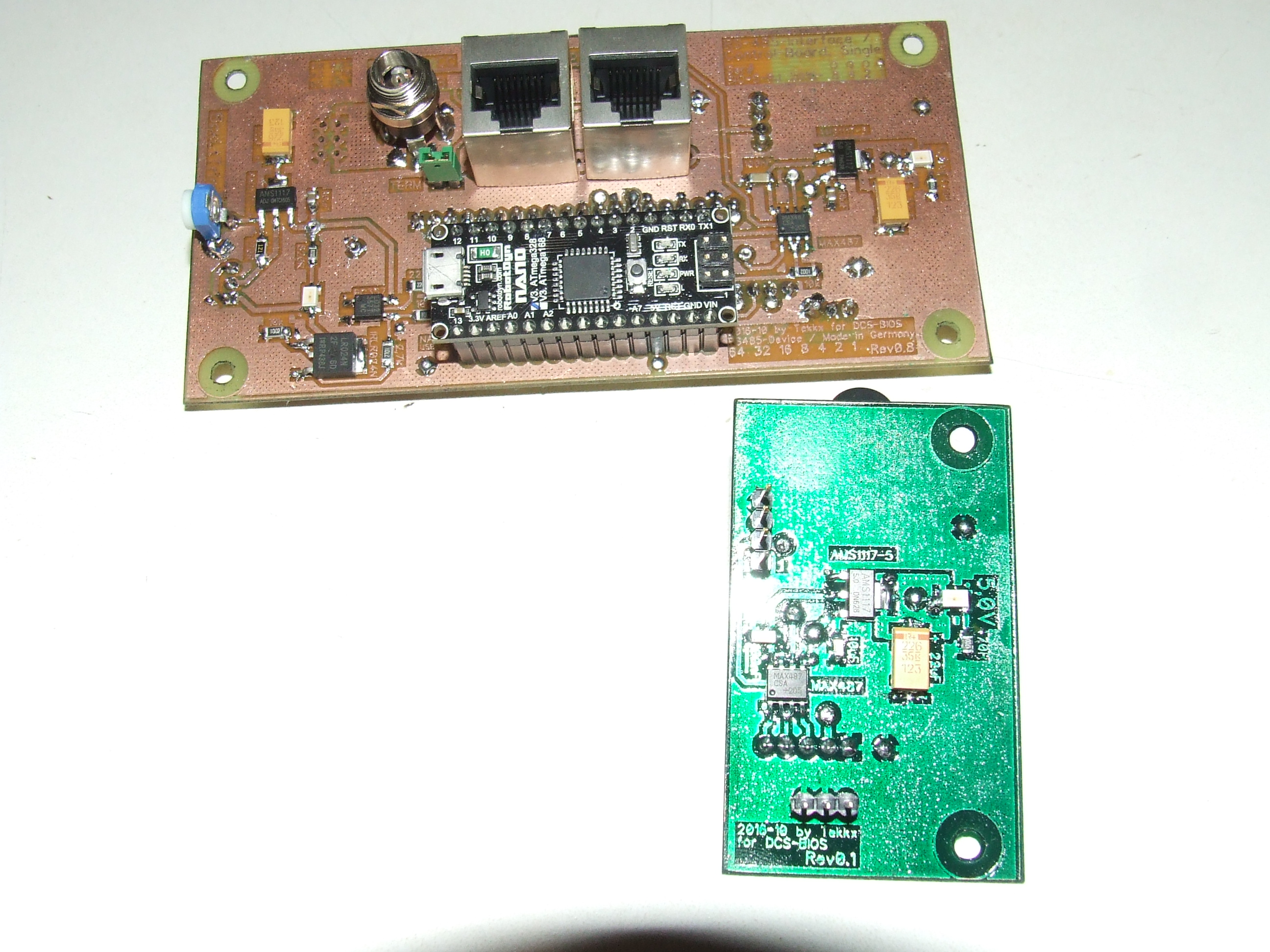
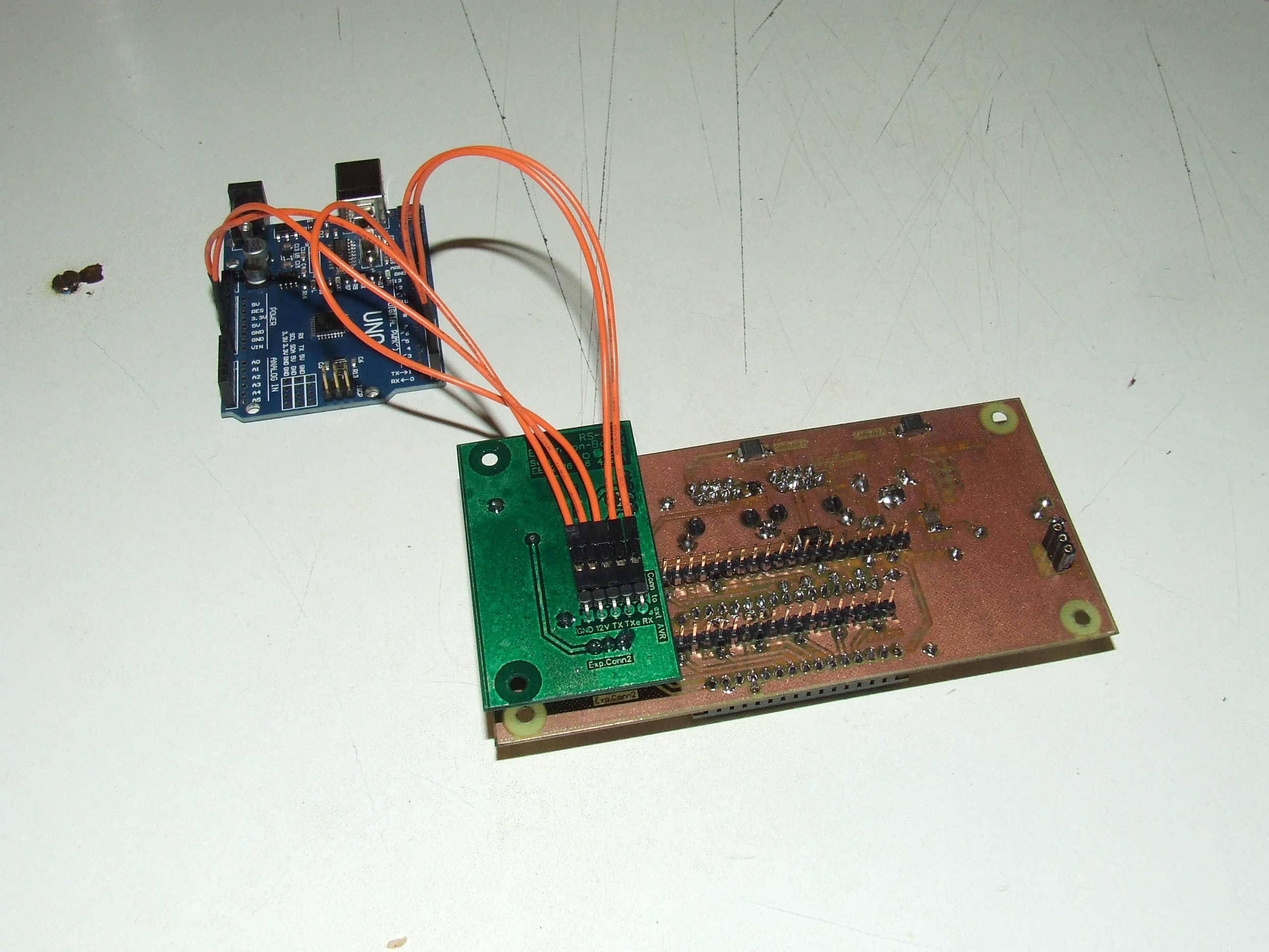
Can I make a branch off RS485-Bus? To return to the Thread's titel I want to become some more essential. I did some thinking about DCS-BIOS and RS485. So came the quest: What if a SimPit-Module needs more than one AVR-Board. Modules with Gauges, driven by steppers could easily run out of Arduino-Pins. So I made a construction, called "Expansion-Board". This board is to hook up to an existing RS485-Interface-Board and provides an interface for one, two or more MAX487 to connect further Arduino to. The problem is, if we want to use standardized Interface-Boards (like me). I made a fast sketch by pencil and paper and took a photo of this "construction". As I am able to quick release prototyped boards I already made a sample that works. Where's the problem, if it works??? My fear is, if it workes on the desk, will it work under life conditions? I have just a very few modules to couple with. So I can't say what will happen if there are 100+ modules are linked. The "Main-"Bus is not broken, instead I make a "branch", where RS485-A and RS485-B forked to a second MAX487. ExpansionBoards are stacked on top of one another. The total length of this branch will not exceed 20 cm (see photos). I don't know ATM how many EBs I can stack. Please risk an eye at my sketch and tell me, what you think (or better: know). I'm not good at theory. My attempt should work (electrically - if we would drive incandescent bulbs). But I have no idea what will happen to the signals, rushing through the Bus.

-
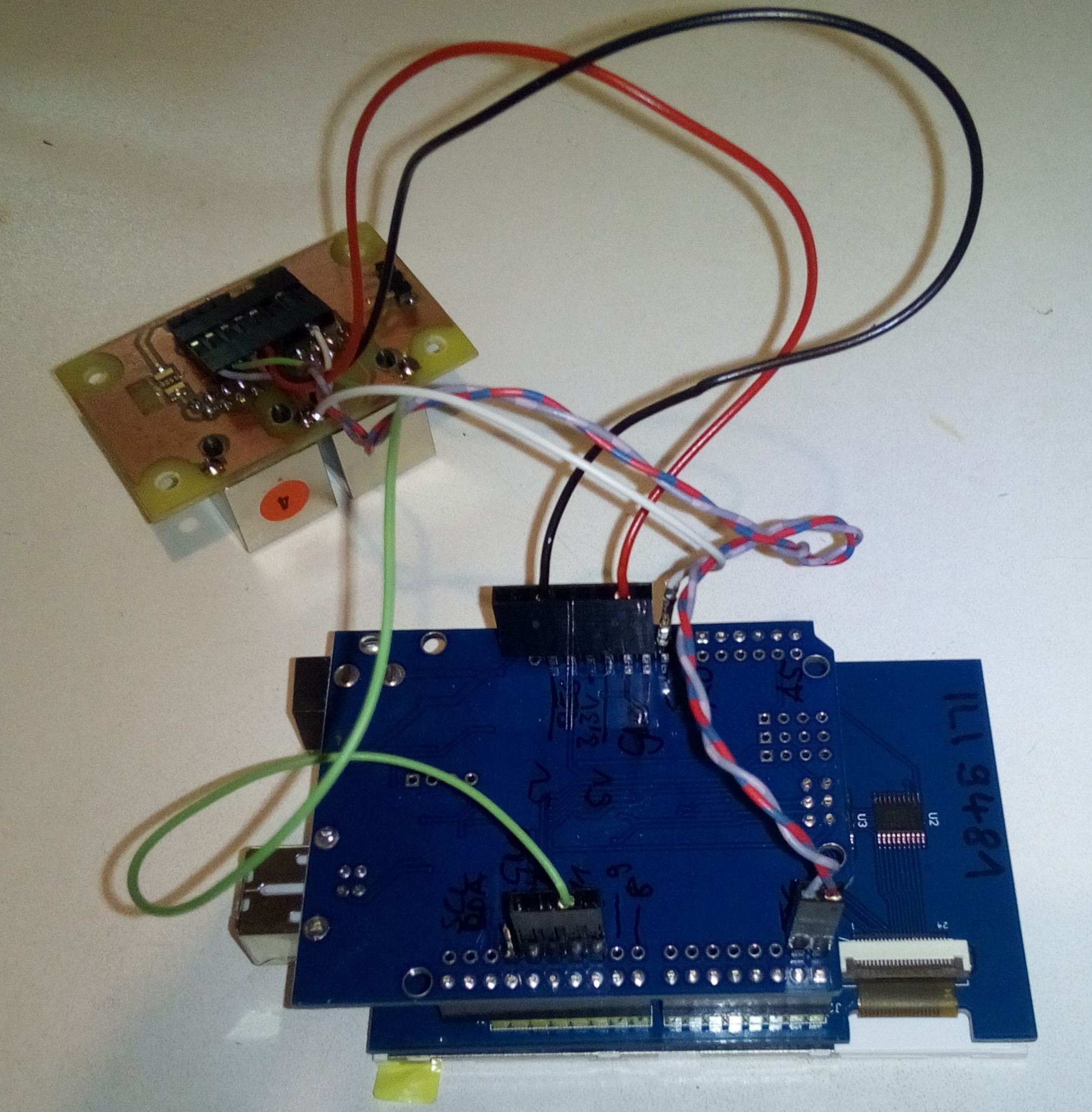
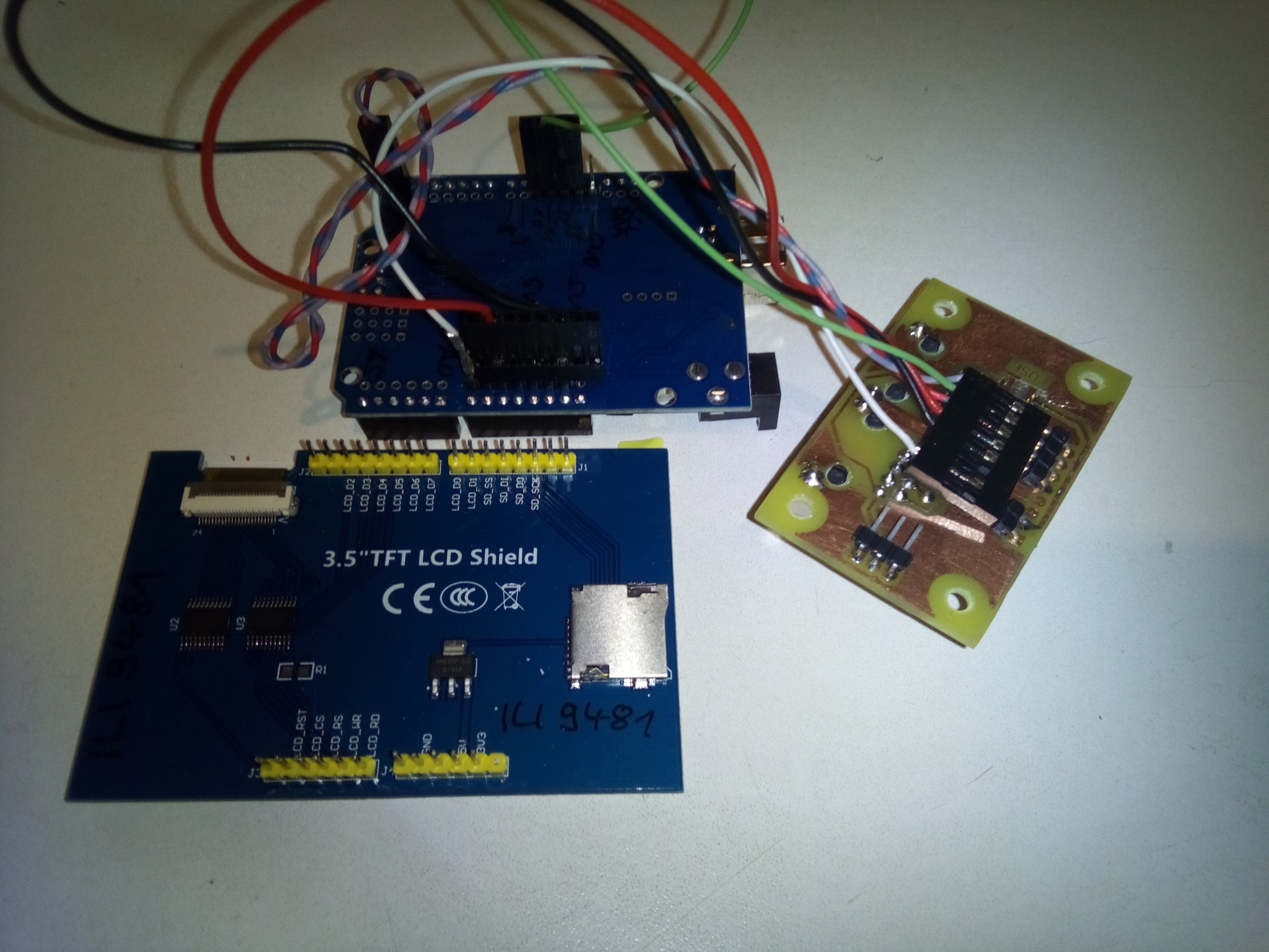
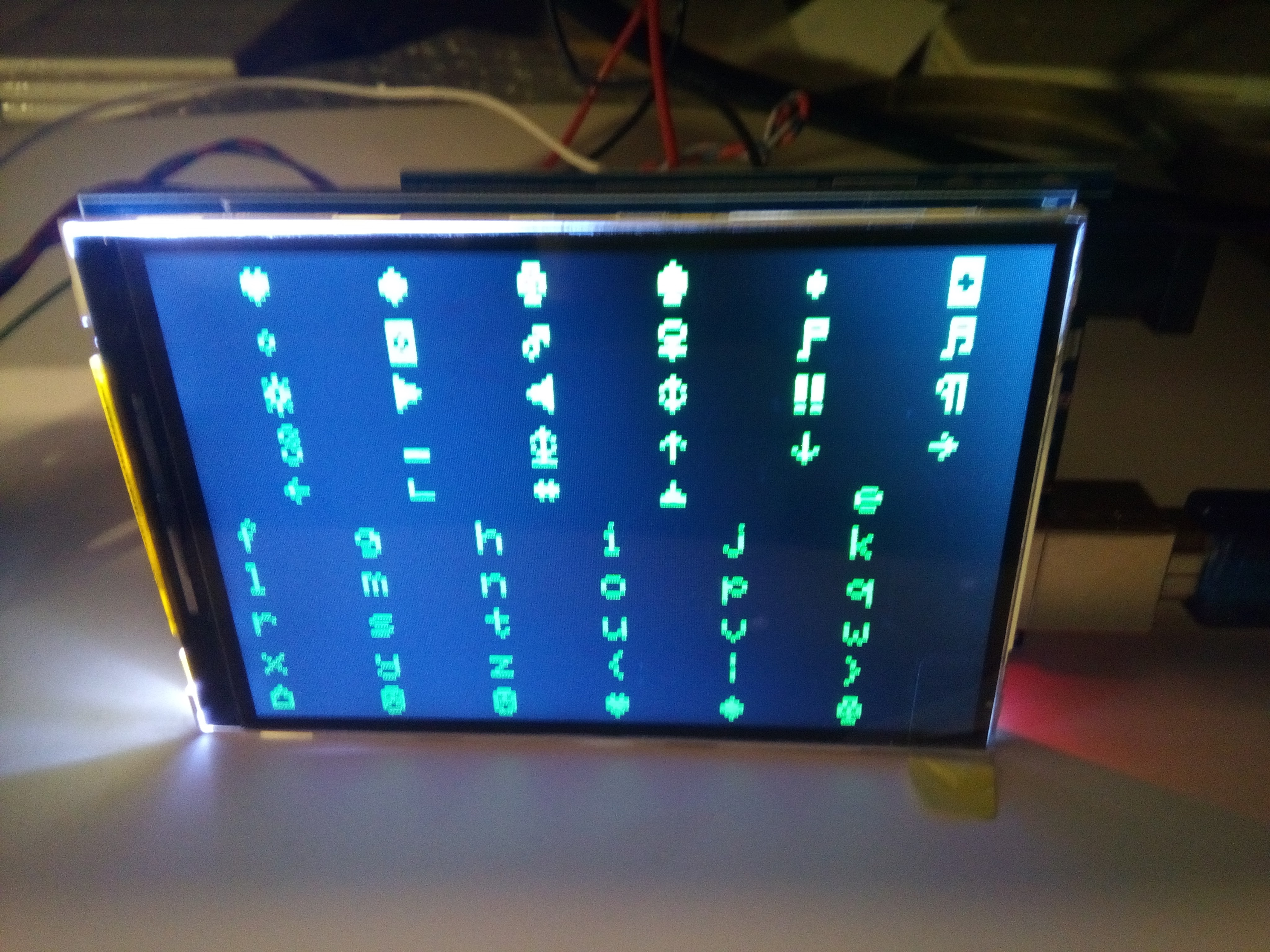
Progress linking by RS485, encountered some problems Dear Friends. Meanwhile I managed to connect the display by RS485. But there is still some work to do. While the display worked without any issues if it connected by USB, it shows - connected by RS485 - a very unattended and unwanted behavior. I attached some photographs of used hardware and some "screenshots". I made also a short . (hope it works, it is my first playlist). Sorry for bad quality. I don't go for an Oscar with that. In the first take you can see the screen is built very quick (quick enough, I think). The next takes show how the trouble cumulates. At the videos is a connected USB to the UNO to be seen. This is just for powering the UNO/Screen aggregat. The onboard AMS1117 on the UNO is unable to manage this. Next step is to improve power-management to feed it all by the RS485-bus. No problem at all. Also I attached a copy of the used sketch. Ignore the commented lines. I will work on them, if this main issue is solved. The unwanted characters appear on the screen just if DCS is running. If DCS is paused or stopped, latest picture stays on the screen until it is unpowered. No matter how long it runs: No further new characters appear on the screen. Most juicy picture is the last one: This happend a few milliseconds before stopping DCS. As you'll see, there are almost all characters are shown as them listed in the ASCII-table. Maybe this gives a hint to someone who knows about serial-communication. During the test the screen-device has been the only slave device connected to the RS485-Master. It makes no difference, if I link other slaves to the bus. I assume some kind of interference between RS485's and Adafruit's libraries. I have no idea, where I should start to debug this. By reason it works by DCSBIOS_IRQ_SERIAL (USB) faultless, I assume a problem with RS485. Is it to slow? I have a loony thought: Is it possible to filter data which sent by the RS485-master? It looks like, the device is receiving data and has no idea what to do with... DCS_CDU_DISPLAY_RS485.ino.txt
-
There are two short questions to answer before I go the next step (increasing speed is the goal): 1. Is DCS-BIOS library compatible to Teensy 2.x (Teensy 3.x are not easy to buy ATM in germany). 2. Is it worth to give Teensy-family a try? I have encountered problems to drive a 3.5 LCD with RS485. It works basically, but many strange things happen on the screen. I blame it (at my stage of knowledge) to the low calculation power of my UNO. If I find some time I'll open a thread for this issue with detailed description of what I did.
-
-
Please stop starting debugging that. It was indeed some kind of Alien: ME! :doh: I have tried to repeat this experiment today. I can't explain, what exactly went up there inside that conglomerate of devices, but I can tell you the reason: It was the first time, I had to test more than 2 Slave-Devices. And there aren't enough sketches available. So I took (in a kind of inebriation - means: euphoria) a working one and flashed it to several slaves.... ... and forgot to set different Bus-Adresses. :music_whistling: This shows, how rugged RS485 is: It worked well, thow this mistake. Maybe it worked faultless just in one direction (DCS -> Slave-Device). On most slaves were no buttons connected to. Just PWM-backlight. My AAP (complete installed) inside the chain worked well. Sorry for wasting your time.
-
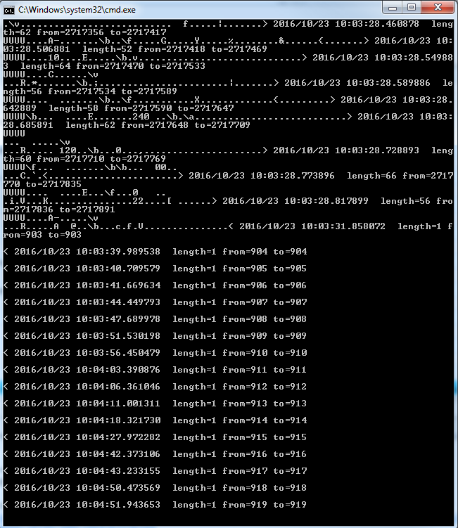
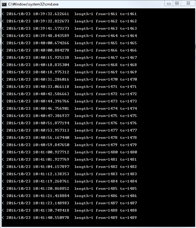
Good Morning, Friends :) Today I made a test of some brandnew "Interface- and Control-Boards". The testbed consisted of a Master with 3 activated RS485-Chains. All 3 Slaves are connected daisy-chained on just one Chain. All RS-485 Devices are equipped with TVS-Diodes. TXenable-Pin is connected to a Pulldown-Resistor to GND by 10k on each Slave-Board. All Bus members are linked by CAT5 SFTP Patch cables. Bus length over all is less than 2 meters (< 10 ft). This hardware configuration runs commonly very stable and safe against stress (disconnecting/connecting new Slaves, removing AVR-Boards, touching wires and PCBs) - as latest tests have shown. Everything ran fine. Communication worked as intended in both directions. No strange side effects. I am very happy with that. After stopping the mission in DCS (and than also DCS) I let the hardware still running. Now I watched some strange thing happen (see screenshot of connect-serial-port.cmd just after stopping and about 15 minutes later). Every few seconds something(?) is sending one byte of code. The interval is not constant. My BIOSConfig.lua is BIOS.protocol_io.connections = { --BIOS.protocol_io.DefaultMulticastSender:create(), --BIOS.protocol_io.TCPServer:create(), BIOS.protocol_io.UDPSender:create({ port = 5010, host = "127.0.0.1" }), BIOS.protocol_io.UDPListener:create({ port = 7778 }) } My connect-serial-port.cmd is REM Specify the number of the COM port your Arduino is connected to: set COMPORT=35 set /A TTYNUM=%COMPORT%-1 mode COM%COMPORT% BAUD=250000 PARITY=N DATA=8 STOP=1 TO=off DTR=on REM socat\socat -v UDP4-RECV:5010!!udp-sendto:localhost:7778 /dev/ttyS%TTYNUM% REM socat\socat -v TCP4:127.0.0.1:7778 /dev/ttyS%TTYNUM% socat\socat -v UDP4-RECV:5010,ip-add-membership=239.255.50.10:127.0.0.1,reuseaddr!!udp-sendto:localhost:7778 /dev/ttyS%TTYNUM% pause Questions: Is there a feasible assertion for this? Have I to go after this? Should I report this to the SETI-Project?
-
This looks really amazing. How do you want to connect this beauty to DCS? I ran here into a problem. I still haven't found a convincing solution to bring TFT and keymap together and link this to DCS by DCS-BIOS/RS485. MEGA2560 hold enough I/Os to connect everything, but it is too slow to refresh the screen quick enough. Have checked this: Is really, really slow. If I use an UNO for the TFT, I'm running out of pins. Even if I plan to link a second AVR (UNO or NANO) by I2C or RS485. My TFT uses all Analog INs (no idea exactly for what for) so SDA and SCL are occupied: No I2C available even if these pins are still free. If I link both AVRs inside the device (CDU) by RS485... I do not know if TX and RX are still "free". At least one digital Pin for TXenable should be available if I set SD-Card aside (shouldn' be a problem). But even if TX/RX are free to use: my programmer's skills are weak. Too weak for this. Workaround (from my noob's position) would be, to connect both boards independent by USB: Unsatisfying! Is there already someone researching this matter and - maybe - found a solution? And - best case - is willing to share this with us? PS: Didn't went for the "Contrast Issue" yet. Lack of time. :(
-
Thank you to remembering my own question... this guy... :) Brought it to life, but have to make some deeper examinations. Something is still strange. Will open a new thread, cause it seems to be a very special problem of my mashine here. Maybe tomorrow. So no further discussing of this here, please. By the way: Is it meanwhile possible to config MEGA or even DUE as Slave? Would help me with my TFT-task. (This is NO pushing nor an urgent request!!!)
-
Hallo, friends. I have a situation here that shows (again) how noob I am. :doh: After an issue with some Trojans and relationship (more than 250k hits by AntiMalWare) I had to renew something here on my mashine. The problem occours now, I can start just one instance of connect-serial-port.com. Second one spits: It has been a long time, I did my first steps with DCS-BIOS, so I forgot the right things (another example of "Make a f...n log of all of your steps. It could be essential some day." Sorry for disobey this simple rule. My ..Saved Games\DCS\Scripts\DCS-BIOS\BIOSConfig.lua looks this: BIOS.protocol_io.connections = { BIOS.protocol_io.DefaultMulticastSender:create(), BIOS.protocol_io.TCPServer:create(), -- BIOS.protocol_io.UDPSender:create({ port = 7777, host = "192.168.1.177" }), BIOS.protocol_io.UDPListener:create({ port = 7778 }) } My connect-serial-port.cmd looks this REM Specify the number of the COM port your Arduino is connected to: set COMPORT=35 (with different ports, offcourse :)) set /A TTYNUM=%COMPORT%-1 mode COM%COMPORT% BAUD=250000 PARITY=N DATA=8 STOP=1 TO=off DTR=on Which of these two lines (with -> ) are the right one. None of them works. While second one is direct copied from Github. -> socat\socat -v UDP4-RECV:5010!!udp-sendto:localhost:7778 /dev/ttyS%TTYNUM% -> socat\socat -v UDP4-RECV:5010,ip-add-membership=239.255.50.10:127.0.0.1,reuseaddr!!udp-sendto:localhost:7778 /dev/ttyS%TTYNUM% pause It looks I went completely ga ga. Please point me to the right place (in some manual e.g.). I am ready to go the very first steps again. Thank you.
-
Thank you Ian. I'll examine that. As usual, that'll take me a while (basically, I have no idea, what I do here :) ) Meanwhile I encountered some small blemish inside the modified font. Sorry, RobinMLi. This will not substract anything of your great work! I was able to fix that thanks to Ians amazing hint to export bitmaps as *.xbm . Strange side effect: Gimp-Export mirrors the hex code! The font looks now exactly like that inside the sim. Simply re-rename it to glcdfont.c and copy it to your Adafruit_GFX_Library directory. Make a backup before!!! If there is still a mismatch: Just let me know. I'm now quiet familiar to edit that :) glcdfont.c.txt
-
Dear Community. After fighting some beginner's issues - to be honest: my learning curve was some kind of smooth - I brought that thing into business. After I've learned some of the basics, it was almost a plug-and-play matter :) I use an UNO with a 3.5"-TFT, driven by an ILI9341. The code is what RobinMLi gave to us. Thank you very much. Without your work I sat still here, staring at a white screen on my knees ;) It looks really good, even the refresh rates are acceptable (clearly less than half a second). So I wanted to put some whip cream on top of the cake: Because my TFT has no interface for dimming the backlight (resp. brightness of the font) and it could be nice to change that to personal taste or to adopt environmental conditions. Althow the DIM/BRT-Rocker has no inSim-Function, DCS-BIOS reads and streams this if there is something happened. I use this to change the color-value of the written lines. It works well, but with a little problem: Just altered lines are shown with the new color - as intended. Is there a single command, that tells DCS-BIOS to re-read (or re-send, depends on the aspect) all 24 lines, no matter if them changed or not? This command should be set each time, the DIM/BRT-Rocker is triggered. I know: It will take a few (felt 200 to 400) milliseconds to refresh all lines on one single rush. But how often you will change screen's brightness? So I don't know if it's worth to cut the TFT-panel to feed the backlite-LEDs with a PWM. This would be qiete more elegant. Of course. This work could be dangerous to the panel... and if a few lines of code can do almost the same job... Here is my code. Put your attention to lines 20 to 44. And there is no keypad yet. ATM I do not know how I'll implement that. Maybe I convert the whole thing to RS485 and couple a second UNO or a NANO for feeding the keypad. So they can share the load. I have to wait, what I'll dream of that matter :) /* Tell DCS-BIOS to use a serial connection and use the default Arduino Serial library. This will work on the vast majority of Arduino-compatible boards, but you can get corrupted data if you have too many or too slow outputs (e.g. when you have multiple character displays), because the receive buffer can fill up if the sketch spends too much time updating them. If you can, use the IRQ Serial connection instead. */ #define DCSBIOS_IRQ_SERIAL #include "DcsBios.h" #include <Adafruit_GFX.h> #include <UTFTGLUE.h> int i = 0; // just for testing/debugging int j = 0; // just for testing/debugging UTFTGLUE myGLCD(0x9341,A2,A1,A3,A4,A0); // set different brightness // bright1 = 0x01E0; // darkest // bright2 = 0x02E0; // values just for reference // bright3 = 0x03E0; // so you know what my intention is // bright4 = 0x04E0; // bright5 = 0x05E0; // bright6 = 0x06E0; // bright7 = 0x07E0; //brightest int cduBrt = 0x04E0; // start value void onCduBrtChange(unsigned int newValue) { // newValue range 0 (left/down),1 (neutral),2 (right/up) if (newValue == 0){ // DIM/BRT-Rocker left cduBrt = cduBrt - 0x0100; }; if (newValue == 2){ // DIM/BRT-Rocker right cduBrt = cduBrt + 0x0100; }; if (cduBrt > 0x07E0){ cduBrt = 0x07E0; }; if (cduBrt < 0x01E0){ cduBrt = 0x01E0; }; }; DcsBios::IntegerBuffer cduBrtBuffer(0x10fa, 0x0003, 0, onCduBrtChange); // problem: just altered lines are drawn with new brightness void printChar(int row, int col, unsigned char c) { int16_t x = 13 + col * 19; int16_t y = row * 32 + 6; myGLCD.drawChar(x, y, c, cduBrt, 0x0, 3); //0x07E0 } /* paste code snippets from the reference documentation here */ void onCduLine0Change(char* newValue) { for(int i = 0; i < 24; i++){ printChar(0, i, newValue[i]); } } DcsBios::StringBuffer<24> cduLine0Buffer(0x11c0, onCduLine0Change); void onCduLine1Change(char* newValue) { for(int i = 0; i < 24; i++){ printChar(1, i, newValue[i]); } } DcsBios::StringBuffer<24> cduLine1Buffer(0x11d8, onCduLine1Change); void onCduLine2Change(char* newValue) { for(int i = 0; i < 24; i++){ printChar(2, i, newValue[i]); } } DcsBios::StringBuffer<24> cduLine2Buffer(0x11f0, onCduLine2Change); void onCduLine3Change(char* newValue) { for(int i = 0; i < 24; i++){ printChar(3, i, newValue[i]); } } DcsBios::StringBuffer<24> cduLine3Buffer(0x1208, onCduLine3Change); void onCduLine4Change(char* newValue) { for(int i = 0; i < 24; i++){ printChar(4, i, newValue[i]); } } DcsBios::StringBuffer<24> cduLine4Buffer(0x1220, onCduLine4Change); void onCduLine5Change(char* newValue) { for(int i = 0; i < 24; i++){ printChar(5, i, newValue[i]); } } DcsBios::StringBuffer<24> cduLine5Buffer(0x1238, onCduLine5Change); void onCduLine6Change(char* newValue) { for(int i = 0; i < 24; i++){ printChar(6, i, newValue[i]); } } DcsBios::StringBuffer<24> cduLine6Buffer(0x1250, onCduLine6Change); void onCduLine7Change(char* newValue) { for(int i = 0; i < 24; i++){ printChar(7, i, newValue[i]); } } DcsBios::StringBuffer<24> cduLine7Buffer(0x1268, onCduLine7Change); void onCduLine8Change(char* newValue) { for(int i = 0; i < 24; i++){ printChar(8, i, newValue[i]); } } DcsBios::StringBuffer<24> cduLine8Buffer(0x1280, onCduLine8Change); void onCduLine9Change(char* newValue) { for(int i = 0; i < 24; i++){ printChar(9, i, newValue[i]); } } DcsBios::StringBuffer<24> cduLine9Buffer(0x1298, onCduLine9Change); void setup() { DcsBios::setup(); // Setup the LCD myGLCD.InitLCD(); myGLCD.clrScr(); myGLCD.setTextSize(3); myGLCD.setColor(55, 0, 0); // seems to have no effect } void loop() { DcsBios::loop(); }
-
Start your Arduino IDE, open Menue Sketch / add Library / manage Libraries (menue items may be some different cause my version is in German) If you did so, a new window pops up: Library Management (I assume) To prevent endless scroll and search use the filter function (top right) and write "DCS-BIOS" there. E.g. if I do so, a single library is shown: dcs-bios-arduino-library-0.2.5 ... @Ian: Some day we have to raise a Monument to you. It's not only your impressive work on DCS-BIOS, it's especially your patient kind of explaining things. No matter which level the problem is or how often the problem occures. Thank You.
-
Cheers Hans. Thanks for coming by. Thow this project is paused ATM (bezels and front panel lie arround catching dust) I did some thinking: To manage this switch-case-monstrousity (I'm not really happy with that) it should be possible to make somewhat like a function (in Turbo-Pascal I'd call it procedure) what catches the output of the - MFD.getState() and - switch(OSB) expressions and spits out what happened. I'm not a real coder (every second command I have to look at the manual or an example - I do the same if I write english texts). So this will take some time. :/
-
I've seen right now (after I wrote my post): This Thread is one year old.... Found it by searching for a related Topic. Maybe it's helpful if someone find it someday. Did you already tryed the keypad library? I use it with one MEGA for two MFDs and some other Gismos on my Front Shield. Here follows the promised code. It is actually written to drive two MFDs. I show you (Topic is CDU) just a part of the code. As you'll see, it is based on Ian's example code. I tryed to comment each significant line, so you'll can adopt it to your special matters. // an attempt to realize ButtonMatrix in DCS-BIOS by Tekkx :) // this is just an example on how I solved the button-matrix-problem :) // send proposals, cheers and booohs to tekkx@dresi.de. #include <Keypad2.h> #include <DcsBios.h> #include <Servo.h> /**** Make your changes after this line ****/ const byte ROWS = 8; // quantity of rows (later 8) const byte COLS = 9; // quantity of columns (later 9) char OSB[ROWS][COLS] = { // Define the Keymap / upper and lower cases MATTER // D2, D3, D4 , 5, 6, 7, 8, 9, D10 {'1','2','3','4','5','6','7','8','9'}, // A0 {'0','q','w','e','r','t','z','u','i'}, // A1 {'o','p','a','s','d','f','g','h','j'}, // A2 {'k','l','(','%','#','<','y','x','c'}, // A3 {'v','b','n','m','Q','W','E','R','T'}, // A4 {'Z','U','I','O','P','A','S','D','F'}, // A5 {'G','H','J','K','L','Ö','Ä','>','Y'}, // A6 {'X','C','V','B','N','M',';',':','+'} // A7 }; // Connect MFD Rows and Columns to these Arduino pins. byte rowPins[ROWS] = { A0, A1, A2, A3, A4, A5, A6, A7 }; byte colPins[COLS] = { 2, 3, 4 , 5, 6, 7, 8, 9, 10 }; // Create the Keypad, initialize an instance of class NewKeypad Keypad MFD = Keypad( makeKeymap(OSB), rowPins, colPins, ROWS, COLS ); /* Instantiate a ProtocolParser object to parse the DCS-BIOS export stream */ DcsBios::ProtocolParser parser; // all other Non-Matrix-Buttons and rotarys follows here DcsBios::LED lcpAnticollision(0x1144, 0x0080, flashLightPin); DcsBios::Switch2Pos masterCautionBtn("UFC_MASTER_CAUTION", MCB); DcsBios::LED masterCaution(0x1012, 0x0800, 24); // just for debugging // MFD-PWR DcsBios::Switch3Pos lmfdPwr("LMFD_PWR", 25, 23); // LeftPWR-RotSwitch DcsBios::Switch3Pos rmfdPwr("RMFD_PWR", 29, 27); // RightPWR-RotSwitch void setup() { MFD.addEventListener(keypadEvent); //add an event listener for this leftMFD Serial.begin(115200); // this value is subject to change??? MFD.setDebounceTime(50); // maybe needless } // end void setup /* Your main loop needs to pass data from the DCS-BIOS export stream to the parser object you instantiated above. It also needs to call DcsBios::PollingInput::pollInputs() to detect changes in the state of connected controls and pass them on to DCS. */ void loop() { char OSB = MFD.getKey(); // weist OSB den Wert der gedrückten Taste zu while (data > -1) { parser.processChar(data); data = Serial.read(); } // poll inputs DcsBios::PollingInput::pollInputs(); } /// --------------------------- void keypadEvent(KeypadEvent OSB){ switch (MFD.getState()) { // gives PRESSED, HOLD or RELEASED case PRESSED: // If someone finds a better solution as switch - case: Let me know, please :) switch(OSB) { // following commands are fired unique if PRESSED // LMFD case 'w': sendDcsBiosMessage("LMFD_01", "1"); break; // L_OSB_1 case 'q': sendDcsBiosMessage("LMFD_02", "1"); break; // L_OSB_2 case '0': sendDcsBiosMessage("LMFD_03", "1"); break; // L_OSB_3 case 'r': sendDcsBiosMessage("LMFD_04", "1"); break; // L_OSB_4 case 'e': sendDcsBiosMessage("LMFD_05", "1"); break; // L_OSB_5 case '4': sendDcsBiosMessage("LMFD_DSP", "2"); break; // L_DSP_+up case '2': sendDcsBiosMessage("LMFD_DSP", "0"); break; // L_DSP_-dn case '6': sendDcsBiosMessage("LMFD_06", "1"); break; // L_OSB_6 case '7': sendDcsBiosMessage("LMFD_07", "1"); break; // L_OSB_7 case '8': sendDcsBiosMessage("LMFD_08", "1"); break; // L_OSB_8 case '9': sendDcsBiosMessage("LMFD_09", "1"); break; // L_OSB_9 case '5': sendDcsBiosMessage("LMFD_10", "1"); break; // L_OSB_10 case '3': sendDcsBiosMessage("LMFD_BRT", "2"); break; // L_BRT_+up case '1': sendDcsBiosMessage("LMFD_BRT", "0"); break; // L_BRT_-dn case 'x': sendDcsBiosMessage("LMFD_SYM", "2"); break; // L_SYM_+rt case 'y': sendDcsBiosMessage("LMFD_SYM", "0"); break; // L_SYM_-lft case '<': sendDcsBiosMessage("LMFD_11", "1"); break; // L_OSB_11 case 'c': sendDcsBiosMessage("LMFD_12", "1"); break; // L_OSB_12 case '#': sendDcsBiosMessage("LMFD_13", "1"); break; // L_OSB_13 case '%': sendDcsBiosMessage("LMFD_14", "1"); break; // L_OSB_14 case '(': sendDcsBiosMessage("LMFD_15", "1"); break; // L_OSB_15 // PWR_Switch outside the Matrix case 'j': sendDcsBiosMessage("LMFD_CON", "0"); break; // L_CON_-dn case 'h': sendDcsBiosMessage("LMFD_CON", "2"); break; // L_CON+up case 'o': sendDcsBiosMessage("LMFD_16", "1"); break; // L_OSB_16 case 'p': sendDcsBiosMessage("LMFD_17", "1"); break; // L_OSB_17 case 'a': sendDcsBiosMessage("LMFD_18", "1"); break; // L_OSB_18 case 's': sendDcsBiosMessage("LMFD_19", "1"); break; // L_OSB_19 case 'd': sendDcsBiosMessage("LMFD_20", "1"); break; // L_OSB_20 case 'g': sendDcsBiosMessage("LMFD_ADJ", "0"); break; // L_ADJ_-dn case 'f': sendDcsBiosMessage("LMFD_ADJ", "2"); break; // L_ADJ_+up // RMFD comes here, is deleted in this example sketch /* */ }} switch (MFD.getState()){ // gives PRESSED, HOLD or RELEASED case RELEASED: // LMFD switch(OSB) { // Released OSBs or Neutral Rockers signal is sent case 'w': sendDcsBiosMessage("LMFD_01", "0"); break; // L_OSB_1 case 'q': sendDcsBiosMessage("LMFD_02", "0"); break; // L_OSB_2 case '0': sendDcsBiosMessage("LMFD_03", "0"); break; // L_OSB_3 case 'r': sendDcsBiosMessage("LMFD_04", "0"); break; // L_OSB_4 case 'e': sendDcsBiosMessage("LMFD_05", "0"); break; // L_OSB_5 case '4': sendDcsBiosMessage("LMFD_DSP", "1"); break; // L_DSP_+up case '2': sendDcsBiosMessage("LMFD_DSP", "1"); break; // L_DSP_-dn case '6': sendDcsBiosMessage("LMFD_06", "0"); break; // L_OSB_6 case '7': sendDcsBiosMessage("LMFD_07", "0"); break; // L_OSB_7 case '8': sendDcsBiosMessage("LMFD_08", "0"); break; // L_OSB_8 case '9': sendDcsBiosMessage("LMFD_09", "0"); break; // L_OSB_9 case '5': sendDcsBiosMessage("LMFD_10", "0"); break; // L_OSB_10 case '3': sendDcsBiosMessage("LMFD_BRT", "1"); break; // L_BRT_+up case '1': sendDcsBiosMessage("LMFD_BRT", "1"); break; // L_BRT_-dn case 'x': sendDcsBiosMessage("LMFD_SYM", "1"); break; // L_SYM_+rt case 'y': sendDcsBiosMessage("LMFD_SYM", "1"); break; // L_SYM_-lft case '<': sendDcsBiosMessage("LMFD_11", "0"); break; // L_OSB_11 case 'c': sendDcsBiosMessage("LMFD_12", "0"); break; // L_OSB_12 case '#': sendDcsBiosMessage("LMFD_13", "0"); break; // L_OSB_13 case '%': sendDcsBiosMessage("LMFD_14", "0"); break; // L_OSB_14 case '(': sendDcsBiosMessage("LMFD_15", "0"); break; // L_OSB_15 // PWR_Switch outside the Matrix case 'j': sendDcsBiosMessage("LMFD_CON", "1"); break; // L_CON_-dn case 'h': sendDcsBiosMessage("LMFD_CON", "1"); break; // L_CON+up case 'o': sendDcsBiosMessage("LMFD_16", "0"); break; // L_OSB_16 case 'p': sendDcsBiosMessage("LMFD_17", "0"); break; // L_OSB_17 case 'a': sendDcsBiosMessage("LMFD_18", "0"); break; // L_OSB_18 case 's': sendDcsBiosMessage("LMFD_19", "0"); break; // L_OSB_19 case 'd': sendDcsBiosMessage("LMFD_20", "0"); break; // L_OSB_20 case 'g': sendDcsBiosMessage("LMFD_ADJ", "1"); break; // L_ADJ_-dn case 'f': sendDcsBiosMessage("LMFD_ADJ", "1"); break; // L_ADJ_+up // RMFD released -------------- // RMFD comes here, is deleted in this example sketch /* */ }} } ; // end void /// ---------------------------- void sendDcsBiosMessage(const char* msg, const char* arg) { Serial.write(msg); Serial.write(' '); Serial.write(arg); Serial.write('\n'); } void onDcsBiosWrite(unsigned int address, unsigned int value) { } // end void onDcsBiosWrite Do NOT copy and paste it. I have still to work on it due to the amount of buttons and no time for do it right now. The keymap is defined for TWO MFDs, switch-case-monster is still just for the LFMD. Maybe I did some coding since last successful test and this semi-finished code won't work. So don't blame it to me, if it happen ;) But you can copy some hints. Also my SWITCH-CASE-construction is not a very elegant solution. Maybe :) Strange order of case ' ' -values came caused by listing them clockwise from OSB_1 and the strange wireing of the button matrixes. It's a hard job to wire 25 buttons and a 3-position-knob + backlite-LEDs on a 20-mm-wide (even double sided) PCB-frame even without to try to make a clean matrix. Designing the keypad matrix of a CDU should be more easy.
-
Thank you, Ian. This is now a complete new discipline and I'll have to chew on for a while :) So many building sites and too little time... :book:
-
Hey, all. Sorry for beeing silent, had a lot of work (regarding real life) to do and so I missed your progress here. Also cut me slack if I ain't understand your partially sarcastic or funny conversation. Meanwhile it looks like I bet on the wrong horse with my hardware... (Link to my screen - if somebody is interested) It looks to me, you all gambling with adafruit, while I have an Eastrising board and screen. While the with the screen (buydisplay.com) given examples - even modified to check different fonts - run fine, I have serious problems to bring robinmli's sketch to life, means: to transscribe his sketch into UTFT-"language". Also wrote the Author of RinkyDinkelectronics.com as an answer to my question "... how to design a 20x32-font..." I think about to open a new thread for not further contaminate this one (sorry, robinmli) cause I think my problems are complete different to these are discussed here :) @hegykc: What kind of sophisticated software do you use for calculating hex-matrixes? Asking just for the case, I have to go the whole way from start. :(
-
Hello, Friends. A few days ago my 3.5" TFT arrived from buydisplay.com. Hoooray! After the first - very wiggely - steps of a bloody novice like me to bring this thing into life (one issue is ATM I can just upload a sketch if I unplug the shield from the MEGA - very annoying and also dangerous to the TFT) that thing runs now as it should. I am very happy. :) While the next step to convert it to a CDU I encountered the first DCS-related problem: The font (by the courtesy of robinmli - thank You very much for your work) is too small. The pocket calculator says, a font 20x32 dots (padding included) is ideal at a screen of 480*320 pixels like mine. After the lecture of this tutorial came out that my life is too short (I'm already 50+) to remake the right fitting font by myself. So came three questions to the surface: - Is there anybody outthere who is willing to provide a fit-sized UTFT-font to us (me)? - Is there a (short) way for change padding (or size) of an existing font? - Is there intelligent life on other planets? Any help (even just a directing tap) is very appreciated.