Tekkx
-
Posts
319 -
Joined
-
Last visited
Content Type
Profiles
Forums
Events
Everything posted by Tekkx
-
RomeoKilo, I got a short question. What kind of acrylic plate do you use for these panels? Your markings and texts are looking so bright! Mine become always grey. I used Acryl, white (milk), translucence 45%. I tested a sandwich-like system with 6mm clear Base- and 0.8 mm black/white Top-Layer. But it could run much more easy with just one layer. Thank you in advance :)
-
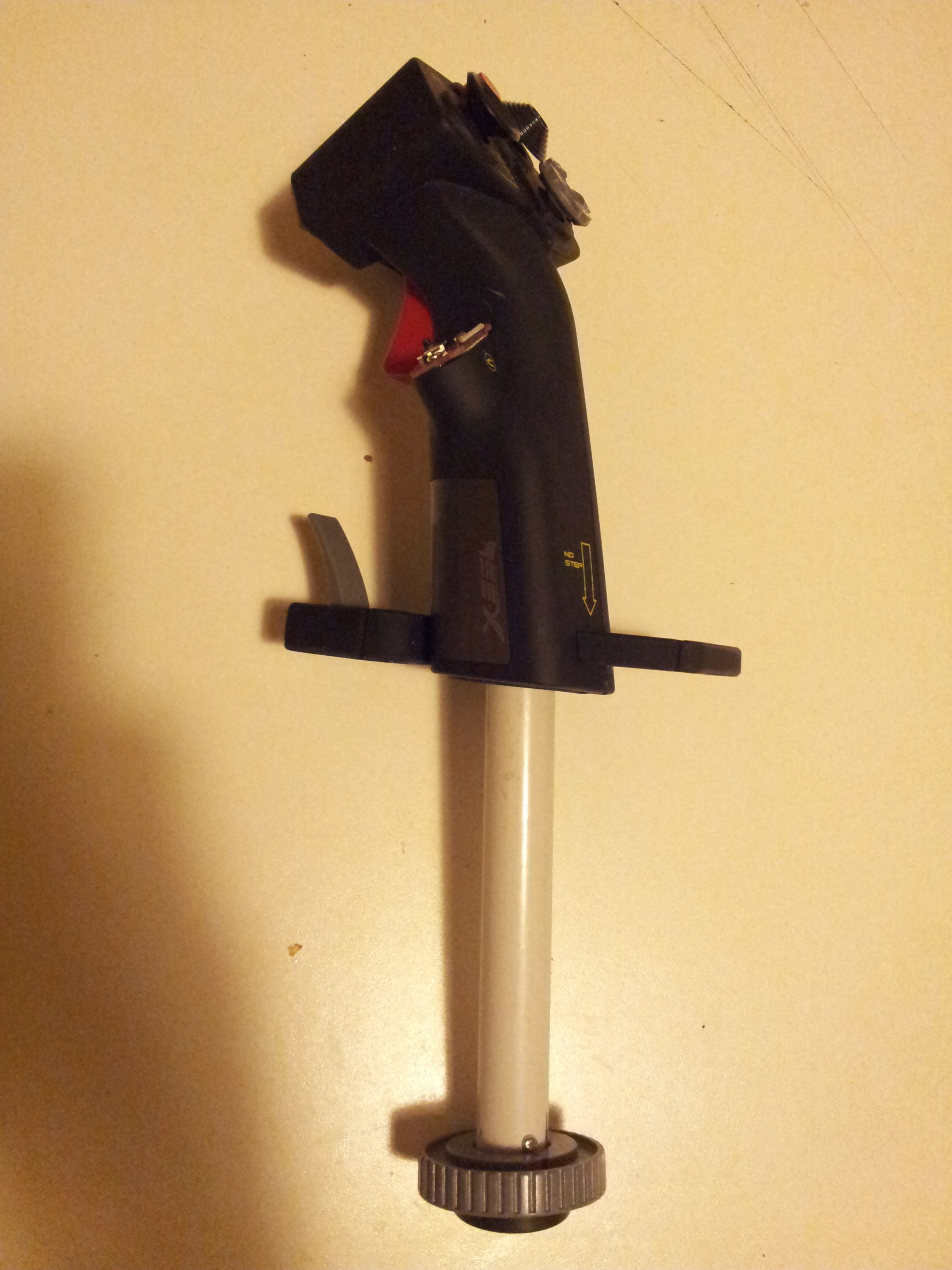
Yesterday I found some time to make a short turn. Just an aerodrome circuit :) After about 5 months teetotalism... The extension is worth every minute I spent with tinkering on :) I landed the fully loaded bird velvety in spite of about 10 knots crosswind. Before modding the stick was landing - even with an "empty" plane - a real challenge to me. One of about three touch-downs ended with a broken leg or at least a flat tyre. So obstrudes the question: Why is to extend the stick not an available option? This could be easy money to MAD-CATZ. BTW: I found a strange behavior of my PC. It's not a special Gaming-/Sim-Computer. I use it also for unimportant things like work and communcation. Due to the open-slider-problem the stick sends different commands to the PC while Stick is removed from the base. So I have to unplug it before removing the stick-extension. ("Remove before no-flight"-Flag is recommended :)) Also I replaced the very small 5-way-mom with a bigger one: That's it! Will add a photograph tonight (after pretending work) .
-
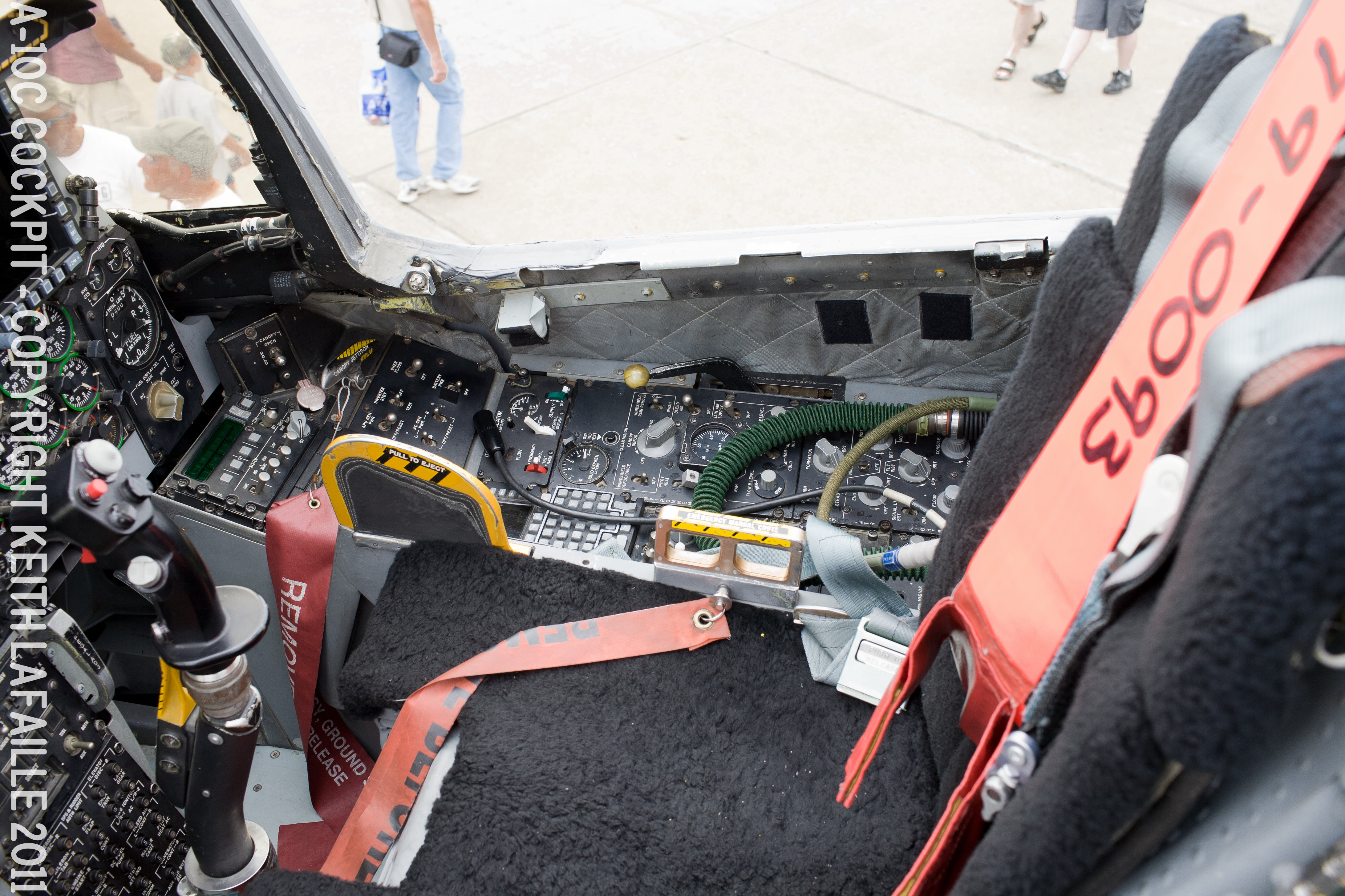
Althow I am very envious about your pit and your opportunities I want to add my "knowledge" :) This is a photo by Keith LaFaille, who shared this (and a bunch of other HighRes-Pics) at Flickr under CC-License. https://www.flickr.com/photos/klafaille/5875323228/in/album-72157626930907793/ Those pics are my source of inspiration and a great reference. It isn't worth a new post so I edit it here: I think due to "scientific" progress and individual claims it could become difficult to find two A10Cs with equal Suites (If this is the official expression for the complete layout) Even a certain bird won't stay the same season by season (maybe mission by mission). I compare Pit-Building to Railroad Modeling (just at another scale): You have to decide to one certain era (german: Epoche), make a snapshot (even of a certain day) and do your best in reproducing that. RK: What I try to say: It doesn't matter, if there are (e.g.) yellow emergency striping or not. You do a formidable work. Your pit is one of those I look at before I do the next step. Thank you for sharing this joy with us.

-
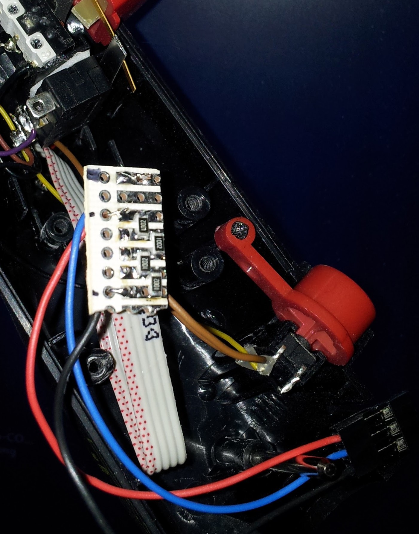
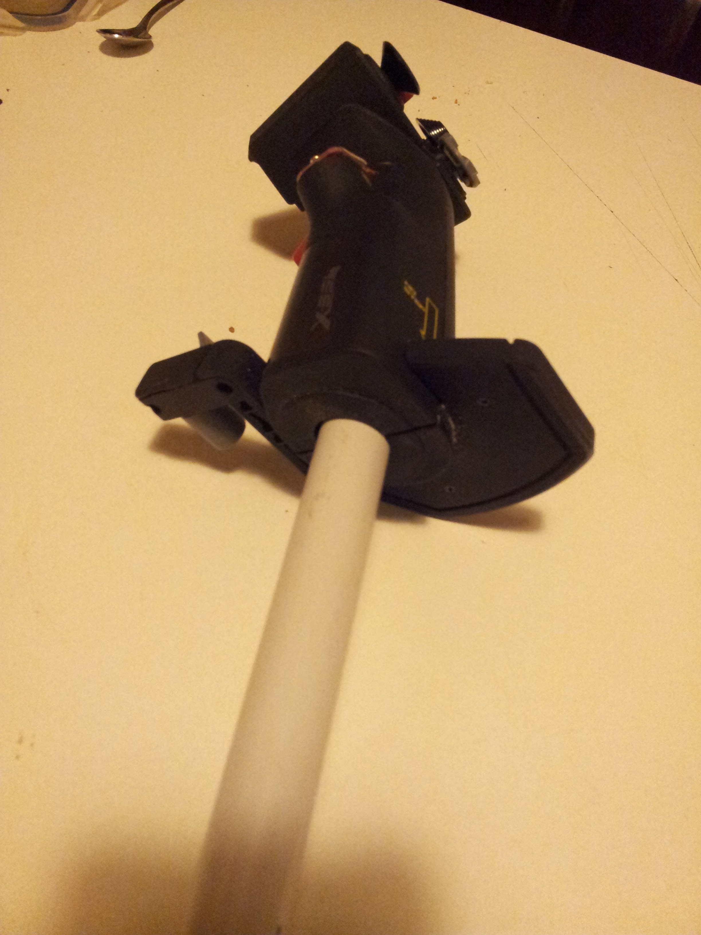
I asked at Mad-Catz - before I went for the screw-driver - for some spare parts. My intention has been to build an extension without making any manipulations at the original hardware. It took them 3 (three) weeks to tell me in just ONE f...'n line, that no spare parts available. LOOSERS!!!! @the_soupdragon: You mustn't think all tinkers and fumblers have been successful at the first time :) It is a natural thing to break things and no problem if you learn sth. this way. Few weeks ago I told my daughter (eight): The best way of sustainable learning is to f_ck up things. Really!!! :) At the end it is NO Magic. Be brave, friends. Be brave! (Don't start with the pacemaker of your grandpa) EDIT: After setup in MAD-CATZ electrically everything works fine. It turned out, my used microswitch is quiet small. It is very tricky to actuate the Z-Axis without warping another direction too. I went already for a bigger one. It was a gamble with the ranges till it worked reliable. Here my results. My formely Rudder-(or Z-)Axis is now: 0...5% do nothing 5...13% CMS right 13...22% CMS Z-Axis (center) 22...45% CMS aft 45...83% CMS left 83...100% CMS forward This values may differ with used Resistors depending on their tolerances and other influences. Also you'll see, it's not linear. I suppose this is provoked by the 1M PullDown-Resistor. I did not fly with this config yet. Maybe, I replace my linear-Array by other values to get a linear behavior at the end. But this will become "something complete different" :) Second Edit: I replaced - thanks to the extension - the RED spring (I cropped it by about 3/4 coil thow it has already been the shortest one) with the (uncut) YELLOW spring. Feels great!
-
Hallo folks. Due to inspiration of spaceravers work, I modded my own X55. Thank you spaceraver. Without your example I'd never had the guts to do it. Look [thread=166174]here[/thread], if you want :)
-
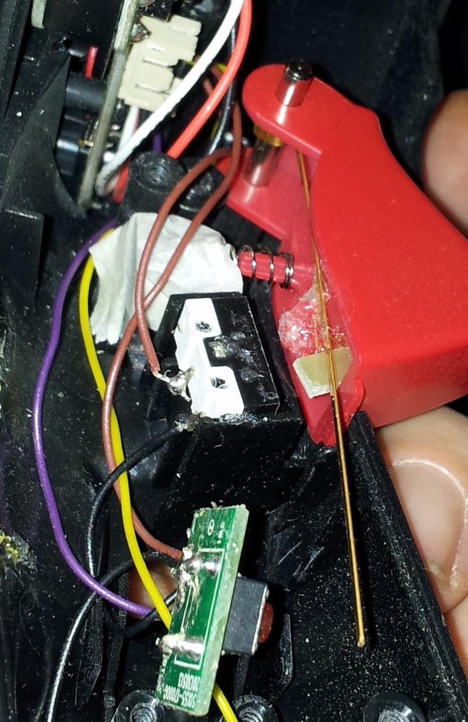
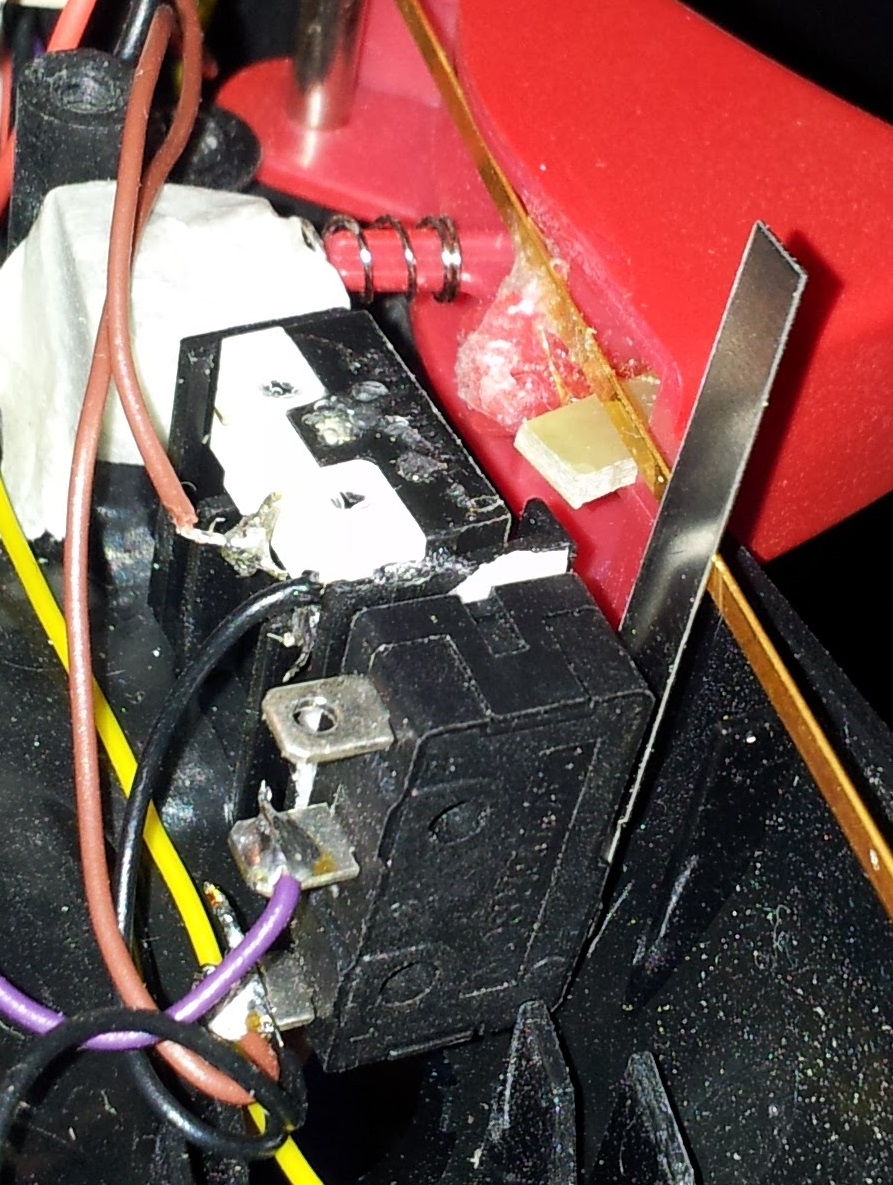
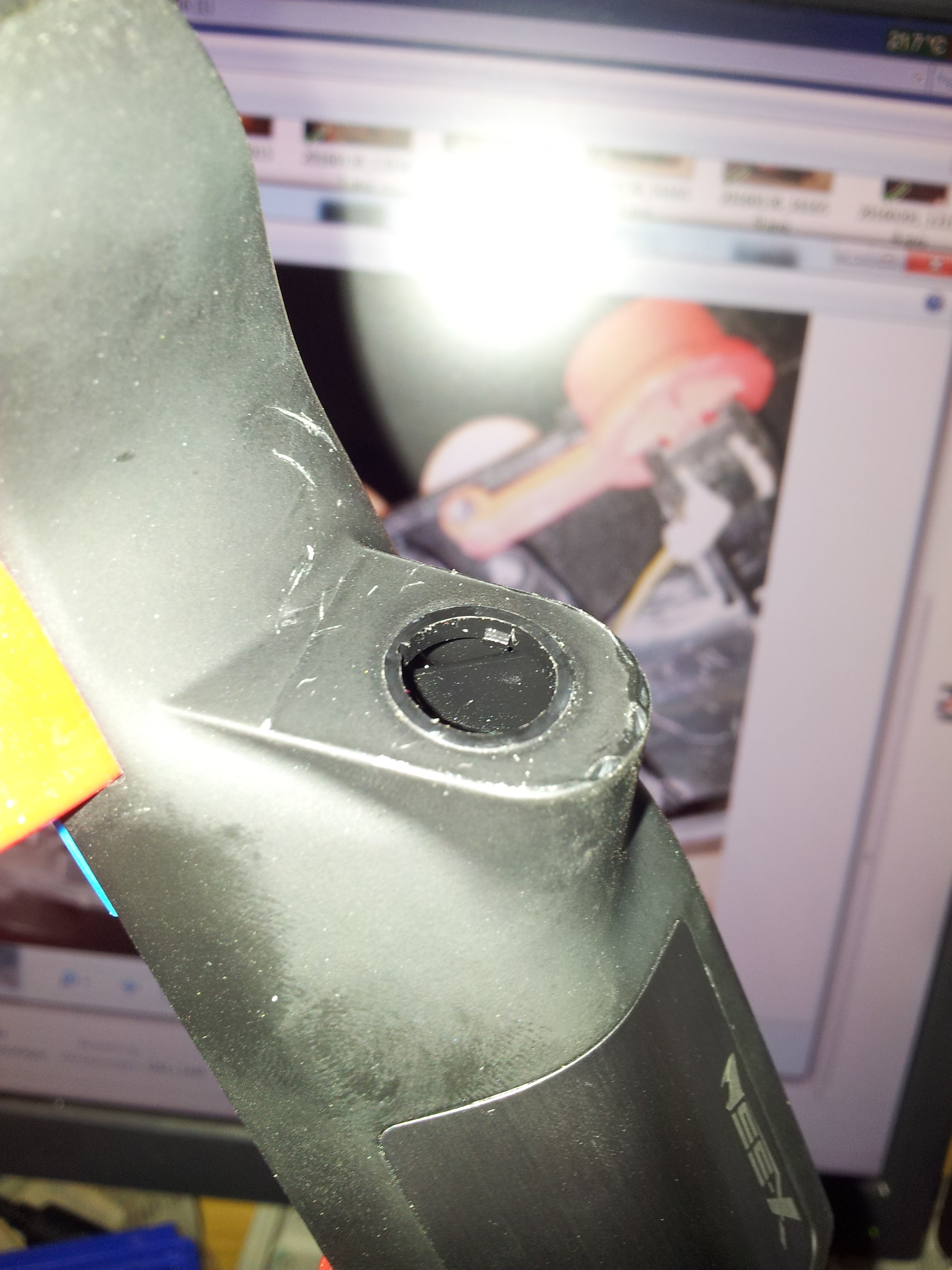
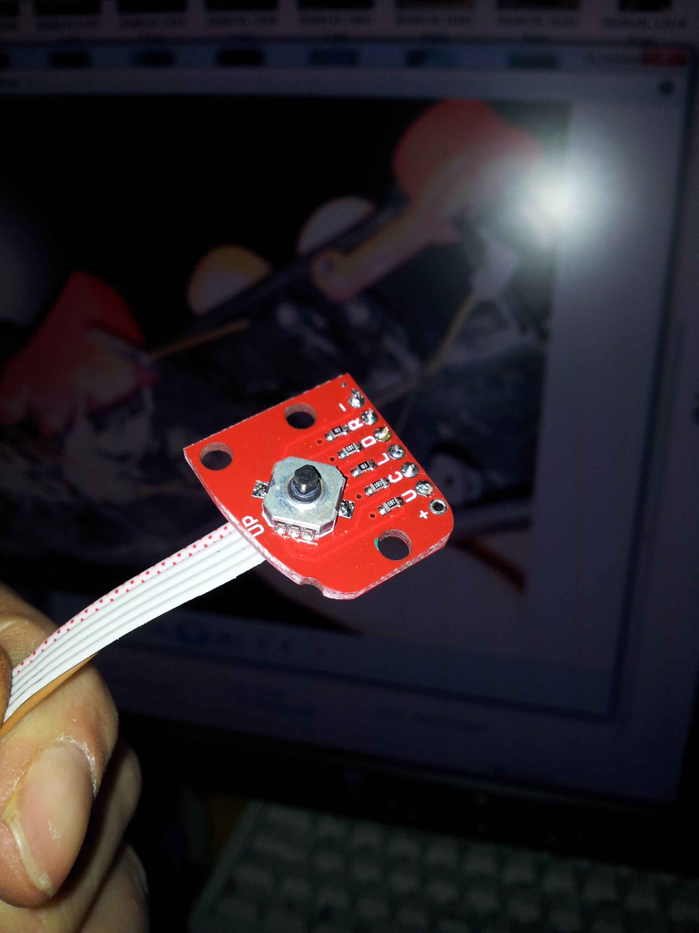
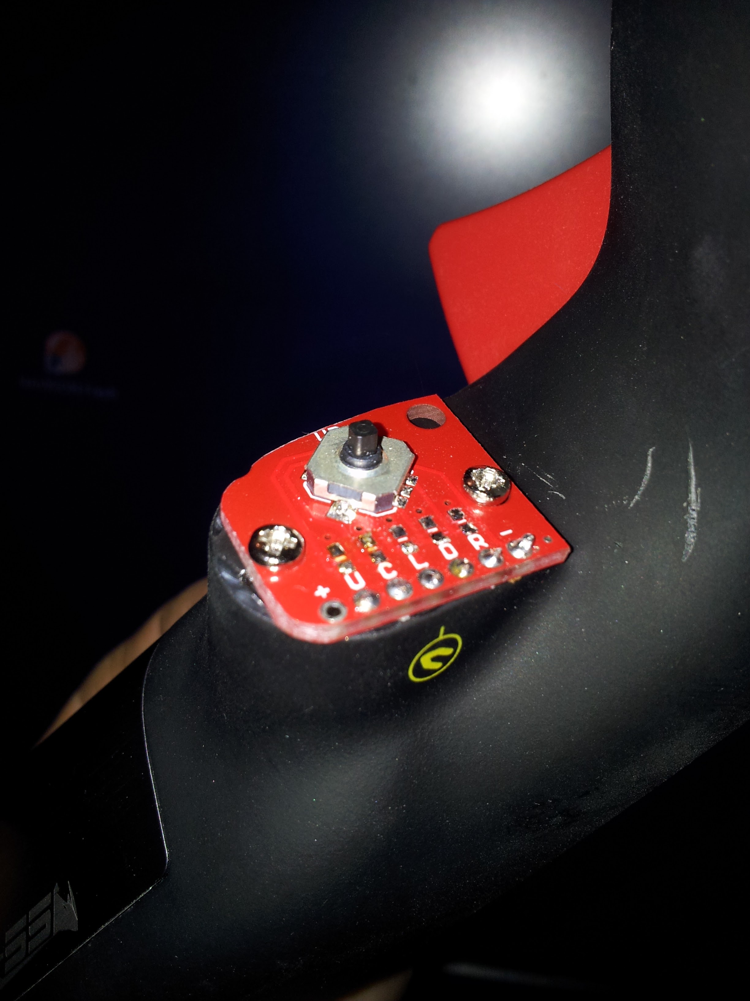
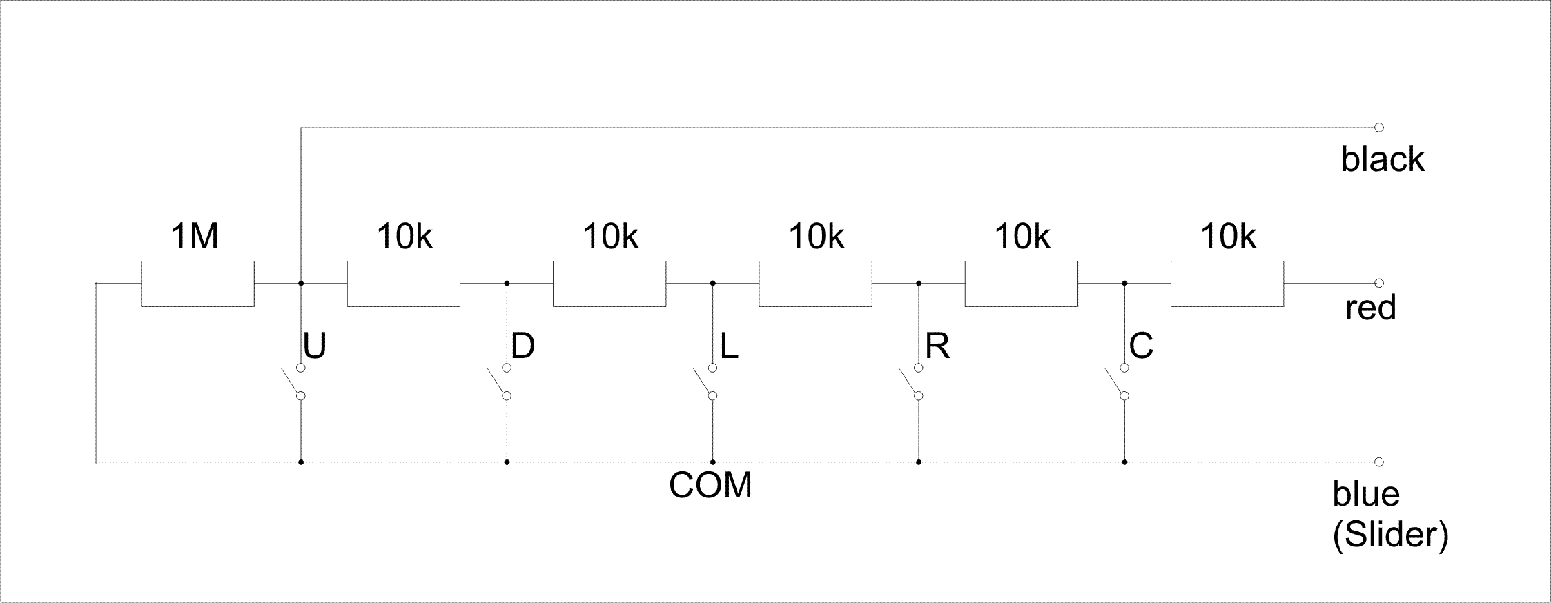
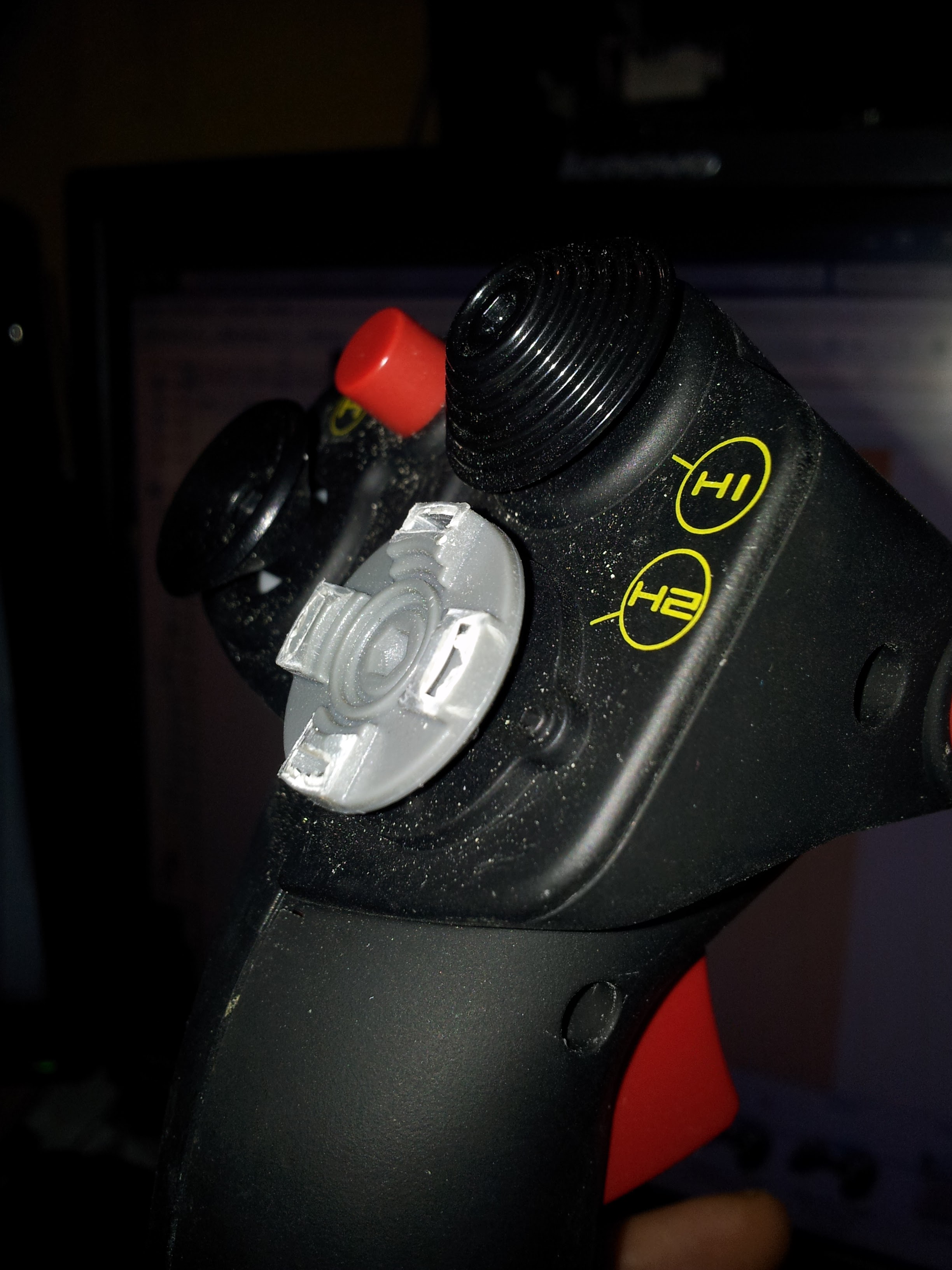
Inspired by the courageous* work of [thread=145293]spaceraver[/thread] I wanted to put some creme on top of the cake and did the next step. Thank You, spaceraver, for this really good work and sharing that with us :) * Courageous because it's a big thing to mod a 200 bucks thing while loosing any warranty. Spaceraver has described anything much better than I ever could. So I start after disassembling the stick and extending the 10-wire-cable. After removing the YAW-Pot you'll loose this function, as spaceraver already observed. So you have one poti left and my thinking was, something to do with. X55 has different disadvantages against TM so (meanwhile I regret to buy this thing - I've seen a TM at Amaz.. at about 300,- €) I wanted to pimp it some. First drawback: Single action Trigger As you see at the pics I added a second microswitch. First I removed the metal actuator from the original one and added a metal tongue to actuate the second micro switch. For easier operation while fumbling (each time I tryout how it fits, the whole shit jumped out of the house) I put a drop of common glue on microswitch and brass tongue. Looks a little bit ugly. Than I put a small piece of a PCB into the trigger (looks a kind of yellow at the pics). This now actuates the originial microswitch. After checking right size I fixed it with a drop of glue. This actuator is to be seen on pics 1 and 2. Than I glued a second microswitch. Here is important - and a little bit tricky - to find the right position for timing of stage 1 and stage 2. That's why I used some sticky tape. So I can (re)move the switch some. Later I'll replace this tape by heavy duty glue - like JB-Weld e.g. Second microswitch is wired as original Button C. This became obsolete (see Drawback 2) Original Trigger is now Trigger second stage. Second Drawback: No CMS-Switch. I found a 5way Momentary Button with a PCB. To bring it to work, I removed the collar where Button C has been before and placed the PCB with Button there. For better matching I shaped it some with a file. Screws are used from the inside of the stick which fastened Button C before. Later, if I became some more familiar with my brandnew Lathe, I'll add a good looking Knob. So how to bring a 5way-Switch into business since you have just 3 wires to connect??? And software expects a poti-like signal? In Mad-Catz Configuring Tool (terrible piece of software) you can each analog axis depart into ranges (german: Spielraum). Don't know how it is in english version of Mad-Catz. So I designed a Resistor's Array (see an obsolete prototype at pic). Each button shorts a different part of this array. So you get the same result as a slider of a poti. First it was some tricky, cause the slider is "open" if no button is pressed. This caused in "flickering" or dithering of the Z-Axis. So I added this 1M resistor as pull-down for the "slider". Maybe, you'll find some better values. I did it with 0805 SMD parts (what I found in my boxes) and it's a very special work to replace these crumbs a few times :) For easy assembling I put a 3pole 2.54mm connector between my Array and the Base. Take care at which length you put it! Mine is fairly misplaced so it is some inconvinient to stick it together :) The stick extension (the primary goal of this operation) is a simple tube of grey vinyl - usually used as cable-tube for electrical installations. This tube has an outer diameter of about 19mm and fits perfectly into the grip and the base. Take care if you turn the screws in the base's end: There is not much place between hub-flange and wires! While assembling I gave the stick a few (sth between 20 and 30) degrees offset counter clockwise. So it is more convinient to use for people with lateral mounted arms. Maybe someone knows the offset-value of the real bird's stick? It looks now some like a rod-doll. But no one will see it ;) So don't tell it to your friends. Third Drawback: Unreachable Trim-Knob (as Ralfidude reviewed. Thank you very much. As I watched this review it was too late... Maybe it helps others to make theire own decission. [ame] [/ame] This problem I solved/attenuated using the Quick-and-dirty-Way: I took a very sharp side-cutting pliers and removed the four "pylons": Zack fertich! That's all. I haven't got a clue about how difficult it could be, to explain something in a foreign language. So I hope you understand what I mean and did. If there are some questions left: Write it here. I'll try to answer ASAP. Also give advice, if you want me to improve my "english" :)
-
I knew this before you wrote it :) Warhog, You'll know I am a great fan of your highly skilled craftmanship. But You (and You all pitbuilders - I am just a half one :)): Where do you take the time for flying from? It's about one month ago I started my bird (just for watching how a lamp looks like and if RS 485 is working - it does) It's (about) 3 Months ago, I had a single lift off. And I don't remember when I shoot something dangerous looking stuff at the ground... And what I did meanwhile: Nothing but fumbling arround with some lights, switches and two panels... So let's lean back and stare at RKs Simpit while salivating our dusty workwear. @RomeoKilo: Sorry for wandering off the subject. Let me repeat: I love your work :)
-
If I see what you've done ATM, I could imagine, you'll find some satisfaction with this: http://mfg.simundza.com/products I couldn't never afford it. Never. But maybe...
-
Hey, Mr_Burns. (see Post #10) I did something in that direction. http://forums.eagle.ru/album.php?albumid=1120 Due to different reason I modified the design some. So I do not use the original fastening system. Everything else is "on scale". I drive them by a Arduino MEGA with keypad library (connected by DCS-BIOS but still off RS-485 bus :(). I have not much time for tinkering, so they are still under construction (but working). Regarding to Post #19: I made my PCB myself by toner transfer and etched it with Na2S2O8. Two Layer etching is a little bit tricky at this size. It took me two attempts. @hannibal: Problems wireing such a considerable project are history. Thanks to the "new" RS-485 bus (by Ian). @romeokilo: I have no idea, where your location is (Diamant-Bike means Germany?). I have ATM some signalling lamps (used for landing gear panel, SAS and EMER) on the bench. I just wait for some electronic parts to finish them for Roll Out. They will look exactly like the real ones. (will promote as soon as everything is complete) Cause I love your pit you could be the first one... Pic shows a very early Prototype (looks little sloppy), R2 and (ATM just as blue print) R3 are really good. PS: @RomeoKilo: If you think, I mustn't hijack your thread: PM me. I'll delete this post in a tick :)
-
Now everything works fine. Reason of fault was - and this shows the urgency of some debugging equipment - a faulty MAX487. There was an "almost short" between RO and RE/DE by some relict of solder paste. IMHO I cleaned it accurate. It wasn't to see, under the pins. While most of you use the MAX487 in a DIP I put my luck on the SO package... and failed. As it works now it shows another advantage of RS-485 against USB: I have not count how often I restarted DCS after uploading a new sketch with a very little change and stared at the loading bar (just enough time to roll another cigarette). Now this runs this way: Plug off RJ-45 (airborne, if you want - cowards use Autopilot, pls), plug in USB, upload the new sketch, replug it to RJ-45: Flap! It works (if not, goto 1) :) Not even connect-serial-port.cmd has to be restarted. Really really good. That's fun. Thank you so much, Ian :)
-
Until the fresh ordered (you see: I follow your proposals) testing kit will arrive, I want to get some theoretical. As many times before I did some thinking (at work, of course) :) My Breakout Boards at Master- and Slave-Side are in 2-Layer-Layout. There was no other way to bring RJ-45, MAX487 and power supply together. So the traces are going crisscross. Ground, Power (12 and 5 Volts) and most signal lines "touching" somewhere. I do not know anything about the quality of my power source and have no option to check this. It is a electronic switching power supply (Wall-Wart) and delivers 12.0 +/-0.6 Volts stable (as I can evaluate with a handheld Multimeter). I have no Filters or shields (except the RJ-45-Shield and the caps on AMS1117-5,0). Also I ran my tests without Termination and Failsafe-Resistors. No connection exceeds 15 cm (6"). So I have seen no reason to add this. Signal reflections shouldn't be detectable. My actual thought was: How sensitive is our construct against such influences as pulsing DC (just supposed) or crosstalk of sth to sth? My gut feeling says "not much". Maxim wrote in the datasheet of MAX487: What is your assessment of the situation?
-
Related to my original post http://forums.eagle.ru/showpost.php?p=2689040&postcount=309 I want to diskuss a new problem with RS-485. (I should add: I don't blame DCS-BIOS. It is still the greatest I've ever seen :)) I do not know how to post same picture twice. So you have to look there. Sorry :( ATM I can't repeat cause a released cable flipped to somewhere at the NANO and it died in a small cloud. There should be some others somewhere.... I NEED A BETTER WORKPLACE! Sorry for screaming. Was a must have ;) Communication seems to work but my hardware sends strange code. This is what Ian said and it meets my own thinking: How to debug this... Good to know: It's the same as before :) Master sketch is (same as Example, I don't have seen any reason to change anything) /* Tell DCS-BIOS this is a RS-485 Master. You will need to flash this to a Mega 2560. */ #define DCSBIOS_RS485_MASTER /* Define where the TX_ENABLE signals are connected. You can connect up to three half-duplex RS-485 transceivers. Arduino Pin RS-485 Transceiver Pin TXn ------------------- DI (driver input) RXn ------------------- RO (Receiver Output) UARTn_TXENABLE_PIN ---- /RE, DE (active low receiver enable, driver enable) If you have less than three transceivers connected, comment out the corresponding #define UARTn_TEXENABLE_PIN lines for receivers that are not present. */ #define UART1_TXENABLE_PIN 2 //#define UART2_TXENABLE_PIN 3 //#define UART3_TXENABLE_PIN 4 #include "DcsBios.h" void setup() { DcsBios::setup(); } void loop() { DcsBios::loop(); } While I read my own post I got this question: How will the Master know, which TX and RX it should use. TXenable_PIN is determined. TX and RX none. Or is it inside #define UARTn_TXENABLE_PIN n ? Slave sketch is (AAP) /* AAP The following #define tells DCS-BIOS that this is a RS-485 slave device. It also sets the address of this slave device. The slave address should be between 1 and 126 and must be unique among all devices on the same bus. */ #define DCSBIOS_RS485_SLAVE 1 /* The Arduino pin that is connected to the /RE and DE pins on the RS-485 transceiver. */ #define TXENABLE_PIN 10 int AuxInstBltPin = 5; // PWM for Backlight #include "DcsBios.h" DcsBios::Switch2Pos aapCdupwr("AAP_CDUPWR", 4); DcsBios::Switch2Pos aapEgipwr("AAP_EGIPWR", 2); DcsBios::Switch3Pos aapSteer("AAP_STEER", A0, A1); const byte aapPagePins[4] = {9, 7, 3, 8}; DcsBios::SwitchMultiPos aapPage("AAP_PAGE", aapPagePins, 4); const byte aapSteerptPins[3] = {12, A2, A3}; DcsBios::SwitchMultiPos aapSteerpt("AAP_STEERPT", aapSteerptPins, 3); void setup() { DcsBios::setup(); } void loop() { DcsBios::loop(); } // Backlighting void onLcpAuxInstChange(unsigned int alt) { analogWrite(AuxInstBltPin, alt/512); // 512 is subject to try-and-error } DcsBios::IntegerBuffer lcpAuxInst(0x114c, 0xffff, 0, onLcpAuxInstChange); While the Backlighting division is still a building site. I should have started with some more common things. Like MCB :)
-
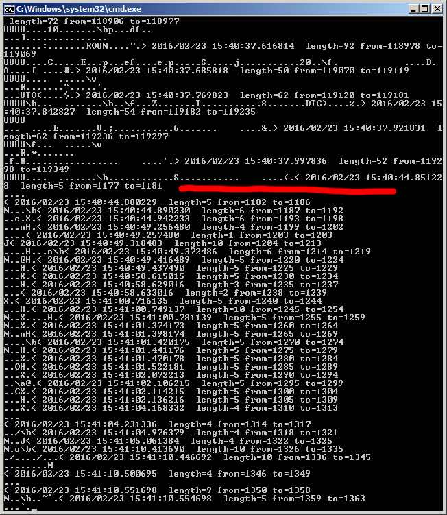
OK. Now I have my hardware running (just at a test bed cause my good look'n Boards aren't working :music_whistling:). RS-485 Communication between DCS-BIOS <---> MEGA <---> NANO seems running. But nothing happens. Neither in Virtual Cockpit nor in AAP (NANO). On both boards (MEGA and NANO) is a flickering light (TX - maybe), communication in cmd.exe runs upwards. Looks fine. To see, what happen if I actuate a switch on AAP I paused DCS. Attached pic shows at red line when I paused DCS. Below the red line is with every switch command an extra line (or two?) appeared. Where can I start to look for the fault. I have no idea, what the shown code means. Is there some hardware broken or is this an DCS-BIOS issue? Thank you.
-
That means, my "code" will work? Edit: (31th of March) Sorry for my sudden dissapearance. I had urgent OffTopic things to solve aside. Meanwhile my Backlight code works. It isn't worth a new post so I set it here (maybe someone finds it sometime :) .... void loop() { DcsBios::loop(); } // Backlighting void onLcpConsoleChange(unsigned int alt) { analogWrite(PWM_Pin, alt/1024); // this value under slash is subject to try-and-error } DcsBios::IntegerBuffer lcpConsole(0x1150, 0xffff, 0, onLcpConsoleChange); // value 0x1150 (or other Lights) you get from control-reference.html
-
Thank you, Ian. (delayed, cause it has been late yesterday) Your answer proves my assumption: I do not know anything about nothing. :) To prevent further contamination of this thread with bloody basics: Can You (or someone else) give advise, where a Stupid like me can step in to become able to find the answer him/her self? Maybe a new Thread? For Beginners? In the previous branch of DCS-BIOS I recognized a pattern and I supposed to know what I did. Now I have to (re)start close to zero to find a similar pattern. Edit: I am right now at work and without way to test it.. After some thinking and digging I found this solution (maybe): void onLcpAuxInstChange(unsigned int alt) { analogWrite(PIN, alt); // maybe "alt" has to be divided by sth. to get a valid PWM-value } DcsBios::IntegerBuffer lcpAuxInst(0x114c, 0xffff, 0, onLcpAuxInstChange); Should it really be that simple? If TRUE: Where get I onLcpAuxInstChange from? Good to know, to enable me (and others) to transpose this to other cases.
-
It has been a while since I encountered problems and it looks like I understood the most important things... Now, after a few weeks of designing PCBs, etching, soldering and killing a bunch of ICs, I'm sitting in the smell of burned plastic and try to bring the whole thing to life. First test object should be my brandnew AAP (still without Light Plate). While programming a MEGA as a RS-485-Master wasn't (thanks to the examples) a challenge and writing (means: copy and paste) the code for the NANO-Slave also has been done with a finger's click... ... I'm now a little bit confused: While I solved the Backlighting with the former version of DCS-BIOS with if (address == 0x114c) { unsigned int lcpAuxInstValue = (value & 0xffff) >> 0; analogWrite(AuxInstBltPin, lcpAuxInstValue/512); // adopt Output to Arduino-PWM-Scale } (example, just reading Potentiometer's position) where should I insert my code now since void onDcsBiosWrite(unsigned int address, unsigned int value) { [i]code code code[/i] } is gone? What did I miss. You caught me completely clueless :cry:
-
Hey Bluethornton. Welcome to DCS-BIOS :) Will it work? For that what I understand of those things: Yes. Thow we'd rather use MAX487. Difference is, you can "just" 32 of MAX485 bring in a daisy chain - MAX487 has the potential to connect up to 128 of them. Look here where I cited from. Even if you use this device, you have to connect it somehow to your master and slaves. That's why we use (or: we're investigating this option) RJ-45 to bring all together. This has nothing in common with TCP/IP of a "normal" Network. Practically you could make a network, but it is much easier to use RS-485 serial communication. We just (mis-)use the RJ-45 connectors. In real world I'm in service for a radio broadcaster. Since "Radio" runs digital, there are many applications which use RJ-45 to connect audio- and/or control-devices. So in the future you have to have a closer look to a RJ-45 before you plug sth. in :) You mustn't think, this (means: DCS-BIOS) came out of MY brain. Your first reading should be [thread=141095] this Thread.[/thread] I am just a very small part of this venture. It's late (here is +1 hour of your local) and no time to tell the whole story. Read the thread and you'll understand what I talk about :) PS: If you think: Wow, what a monster of Thread... I have no idea how many pages of manuals and instructions I've read during the last weeks to understand just a small part of the basics of serial communication. As I wrote in the first line: Welcome! You'll see: It's worth every minute you'll spend with it :)
-
Because we are at the DCS-BIOS discussion close to 300 posts (many Off Topic - partially blamed on me) I felt free to open a new thread :) I suggest to discuss DCS-BIOS related hardware issues just here. As I promised a few days ago (see here, if you want), I did some tests about current load and RJ-45. My testing arrangement consists of - Lab power supply 12V up to 5A - RJ-45 connector - Cat5 Patchcable 5 meters (factory compounded) - Load (different halogen bulbs) and the whole way back. So I had 2 connectors and 5 meters (about 15 feet?) test track. To tell the short story: Att: All results are not scientific affirmed. Different systems are impacted by other important (or relevant) influences (e.g. heat accumulation under casings...) Five Amps are definitely too much :) I made a short by accident and a trace at the PCB burned immediately in a very in-spectacular manner (means: without flames, smoke or explosions). So I have not to regret I don't made a Video ;) This shouldn't be something new to most of us. Right now runs a 20 W Halogen and the system is stable. Amperemeter shows about 1.5 Amps for about one hour now. Cable, connectors and PCB are slightly warm. Safe! Voltage drop at 5 meters AWG 26 (incl connector contacts) is about 0.7 Volts per Lane (one wire, one way). This was at 12V and 1.5 A. So IMHO there is no need to go up to 24 Volts at the "Main-Bus" (contrary to my expectation)... besides you need it somewhere. Conclusion: This looks OK to me. Weakest part of the chain are the traces at PCB. RJ-45 connections are a comfortable and easy to use way to bring all devices into business. Anyway I'd suggest not to exceed 1.0 Amp per wire. Also I suggest NOT to use home made Patchcables. (History has teached me: If a Local Area Network (LAN) is broken: Look at the home crimped receptacles first!!!) Voltage drop is not considerable since a NANO needs 7 Volts at least. In my system I splash out one AMS1117-5.0 (fixed voltage regulator) to each MAX-487. So there are 5.0 Volts stable and I do not need a 5-Volts-Bus. One AMS1117 is about 50 Cents (including chicken feed - 2 capacitors on IN and OUT). A small amount for a high value outcome. If there are other heavy loads at your modules (e.g. Servos or Smoke'n'Smell-Generators*): Provide them with an extra Supply. * Smoke'n'Smell-Generator is a device, that makes real Firefighters come to your house if DCS-BIOS sends e.g. ...LEngFire(0x10da, 0x0008, ...
-
That is also OK, but more used if you monitor your staff :) If you read some manuals or sheets it's OK, but if you see sth. smoking you'll never forget. ;) :poster_offtopic: BTW: I did right now a calculation of my income 2015 (ordered by the "Finanzamt"). All in DCS and DCS-BIOS involved costs are at 1350 Euros. Just for tools and components. :doh:
-
Due to some acquired knowledge about Toner Transfer I was able to design and (cheap) make a small batch of RS-485-Interfaces with RJ45-Connectors. Still I wait for the MAX487s from China. If these items are arrived (maybe next week) I'll do some stress tests about current load (with a fire extinguisher in sight). German say "Probieren geht über studieren" (tests are better than science) :) I am prepared to sacrifice two of these Interfaces. So we definitely will know how much load this construct will be able to carry without our birds go up in flames. Also I hope to identify the bottleneck. (traces on PCB, connectors or CAT5-cable) Actual I think the most important problem will be voltage drop on long distances. Edit: Right now I think about 24 Volt on the line with 12V-Stabilizers on each module... Will follow this if my assumption will become true.
-
Thank you for the quick reply. Reading your Document will take me a few days ;) But I will do!!! Thats OK. But how to determine, what impedance my cable is? I'll take this as a recommendation to use wellknown cable. As I work as an "Audio-Engineer" I will elect a cable from there. Will see. That's well known to me. Thats why it's called Termination :) (Abschlusswiderstand in german) This is a very useful hint. I had in mind, not to solder some resistors before I know exactly bus-structure. I lost off mind, that most of our systems are "dynamic" and nobody knows where the module will be later in the "chain". So I have to do some further development :) Do you rember, I made such a suggestion few weeks ago?
-
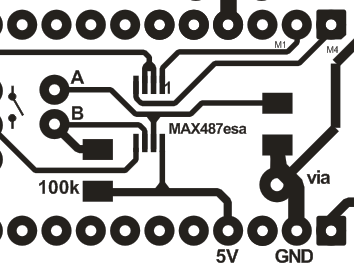
Meanwhile I did some progress in designing and understanding the RS485-DCS-BIOS Interface. Anyway I'm a little confused about dimensions of Termination. What I've learned is, it depends on the total length of the Bus. To calculate this is beyond my horizon. Experts (spread over the Internet) give different proposals: They vary from 120 Ohms to 100 Kilos. I can't imagine, that 120 Ohms are a good decission. I feel this close to a "short". Could someone share his/hers experiences or knowledge? Is there a table or a formula to calculate this? Attached picture shows my actual situation. Terminator between A and B is on Layer 2 and so invisible. Pin Rows belongs to the socket for NANO. PS: To all None-Electronics: You see just the landing pads where IC and Resistors are to solder to :)
-

Get no Emails on new Posts in subscribed Threads
Tekkx replied to Tekkx's topic in Forum and Site Issues
After almost one month and about 200 views I think I have to push this thread. Last weeks I missed some important news cause I received not a single notification last 7 Weeks and so I have to catch up a lot of posts. Not easy at a foreign language :) Maybe this time is there someone who reads this and could help me. Please! -
Meanwhile I found another solution: Suddenly I discovered a complete row of unused Analog Pins. Surprise!!! So my situation has become relaxed :) @Ian: Testing at a breadboard BEFORE etching a PCB is always a very good idea. But before that I have to persuade some chinese people to send me some :) It is not that easy as I thought: There are so many different packages with different pinouts. I ordered a few minutes ago some Max487esa at 10 Euros per 20 pcs. They will arrive mid of Feb :music_whistling:
-
Sorry for disturbing. I'm right now on designing some new boards (I try to make a SAS with MagSwitches). And before I do something stupid is there an important question: (it's a noob's question) Is PIN13 of the NANO (designated as Digital) able to control the MAX487? I love it compact and so I ran out of pins and it became a little bit tide at the PCB :) Edit: Oh. I forgot. Ian: Congratulations. I'm so glad you made it.