yogi149
-
Posts
376 -
Joined
-
Last visited
Content Type
Profiles
Forums
Events
Everything posted by yogi149
-
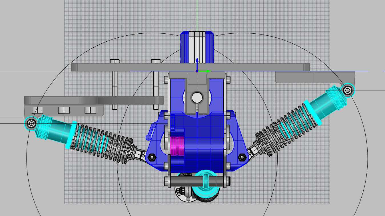
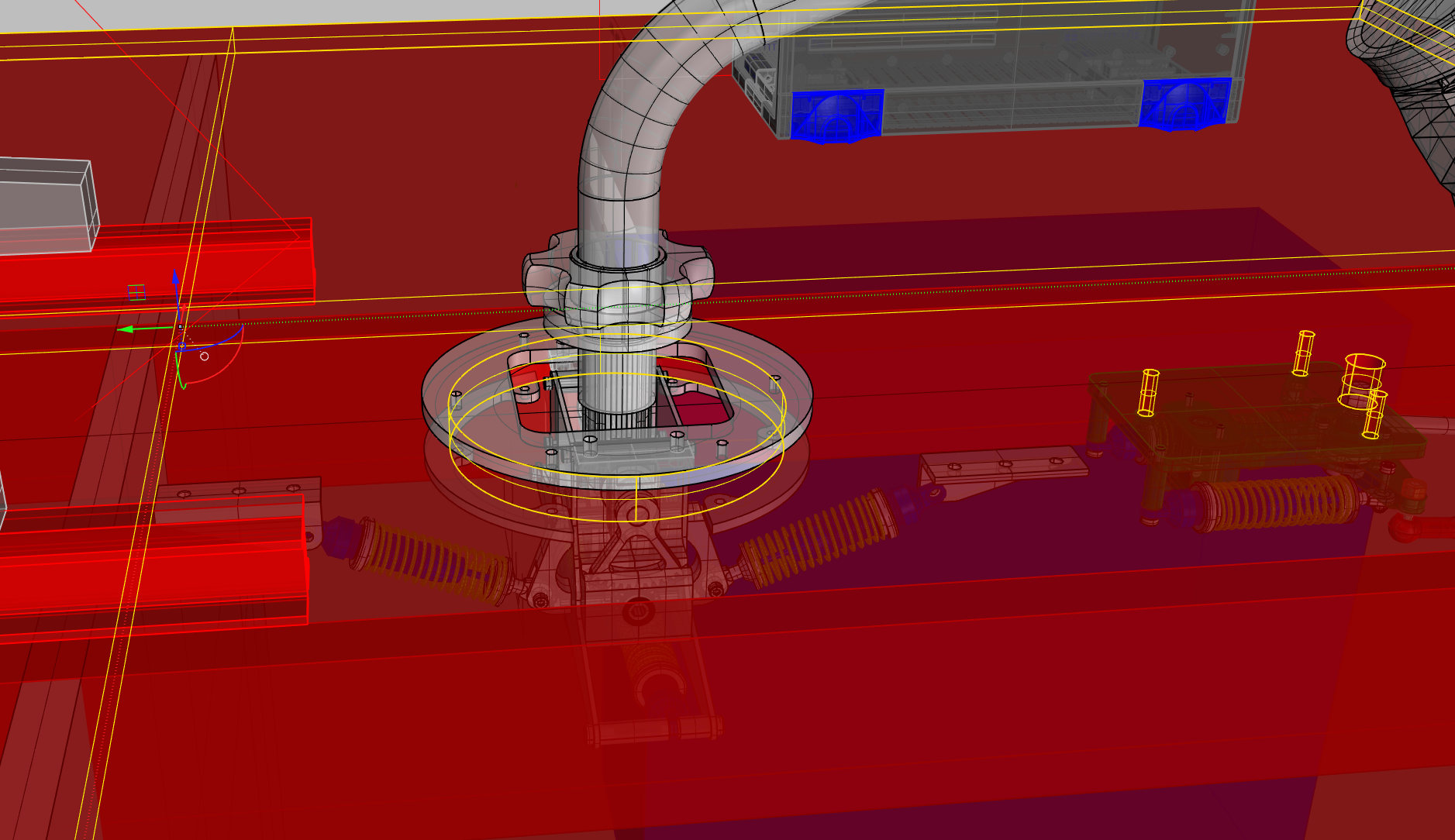
 Hi here is the reason, why it makes differences for the mounting: left side is similar the version I use for my pit. The socket for pitch-axis is mount on the upper edge of the floor. The sockets for the damper are mount under the floor. The circle describes the point for the damper traveled half way. In my pit they were not connected with the clamp, this would be a possible mount kit for the UH version. with these clamps you only need a single, but big, hole in the floor. All fasteners uses the clamps. On the other way I can make a template or even an aluminum plate for screw the whole unit under the floor.
-
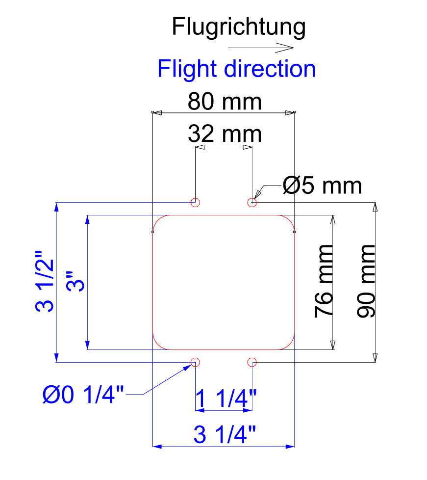
Hi, perhaps this pictures help a little more. [ATTACH]164857[/ATTACH] these measurements are for mounting under the floor. the black dimension are in "mm" the red in "inch". All dimensions are taken from the theoretical center of the cyclic. I try to add a floor clamp for mounting in a single hole. The damper socket will be fastened direct to the bottom part of the clamp. I have to make it the same way for my FTR system, because I need a specified position for it.:music_whistling: BTW: are the "inch" measurements readable in this form or should they be in decimal too?:helpsmilie:
-
Hi Trip, :music_whistling: That is what I tried to say, but I think now it could be misunderstood.:cry: I try to design a template for the drilling position for different floor thickness.
-
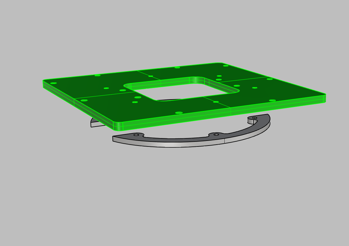
Hi Bad, for my EC-120 simpit I used an additional plate from 6mm aluminum. For this I could make a round hole in my floor an use 6 M5 screws for the 2 clamps. I can send you an UH specific clamp
-
Hi Chic, the anchoring points depends on the floor thickness.:music_whistling: The damper have to be halfway in the center position.
-
Hi, does it help?
-
Hi, I changed the 2 files above with additional measuring in inch.
-
sorry bad. here is the drill template, next days I add an template in the shop too. (edit: done :music_whistling:) Cyclic-mount1.pdf If someone will use the printed PDF to lay it directly to the floor, please print it without any resizing on a DIN A4 sheet of paper. The springs .... Before I changed to my FTR prototype I used the springs with a middle compression. They will not center absolutely even with the max compression. Around the center position the forces cancel each approximately. As we learned in the FTR thread there are no centering forces in a hydraulic system without trim-function, so the springs should be removed.:music_whistling:
-
Hi and sorry. The "normal" products are on the road now, with some minor mods for better assembling. Yesterday we delivered the last delayed item. Now I can go on with new designs as the bottom box and the mounting system. And the FTR system, when I can find it under the dust on my simpit.:(
-
Hi Trip, as I read in the description: "Supplied with connecting socket that plugs into BU0836A and two rows of pin headers." So soldering should not be a problem.
-
Why? As I see it, it will be stacked via pin heads straight to the joystick controller. The buttons will be connected in the same way as on the BBI board.:pilotfly:
-
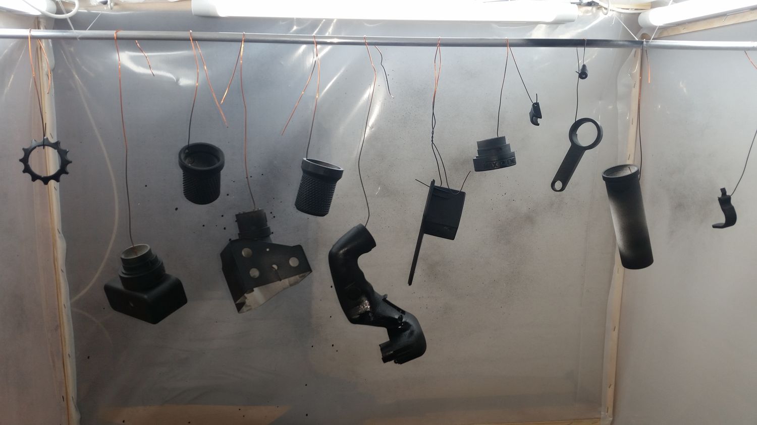
Hi acdelta57, this last list is nearly correct. You forget the collective base. The new joystick controller are order but didn't arrive yet.:cry: When they arrive, there will be a new item in the shop. Leo Bodnar created an breakout matrix board, that can be attached to the joystick controller to make the using of all 32 button very easy. sorry for answering so rare, but those damn days have only 24 hours.:huh: And yesterday I got an additional workspace to get the look for my visible aluminum parts better. my first try with glass bead blasting
-
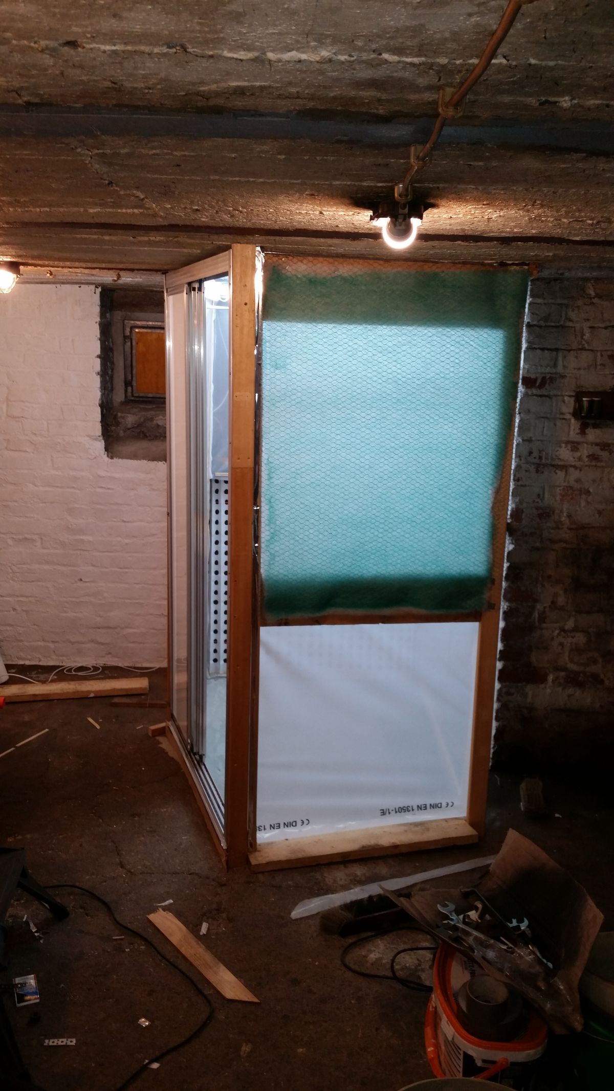
:music_whistling: more than ever, I think. Sorry for late answers and bad response. The circumstances shouldn't be an excuse for non communicating.:cry: Some customers know about the issues, but the leaving of my employee results not only in reduce the manpower. Unfortunately he leaves some tools in nonworking condition, so they have to be refurbished too. Additionally I have to build a paint both, because I do not want to use colors with solvent in our workplace, like he did before leaving.:mad: inlet filter, particle trap, particle filter and activated carbon filter in front of the outgoing blower. now I can restart the business and ask for only a little more patience. I know that all these "excuses" sound familiar to some of you, but I think that this was our last try with employees. If the business grows, as we hope, more part manufacturing will be outsourced.
-
Helicopter control mounting?
yogi149 replied to Mr.Fenestron's topic in PC Hardware and Related Software
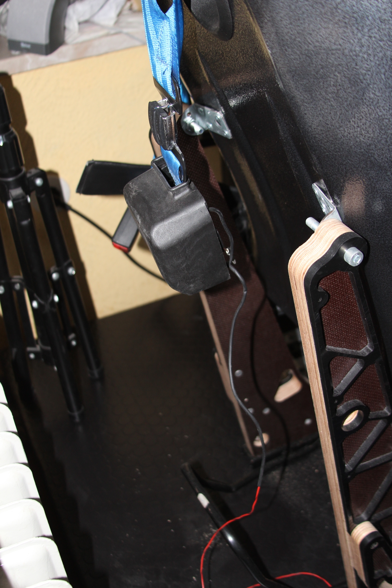
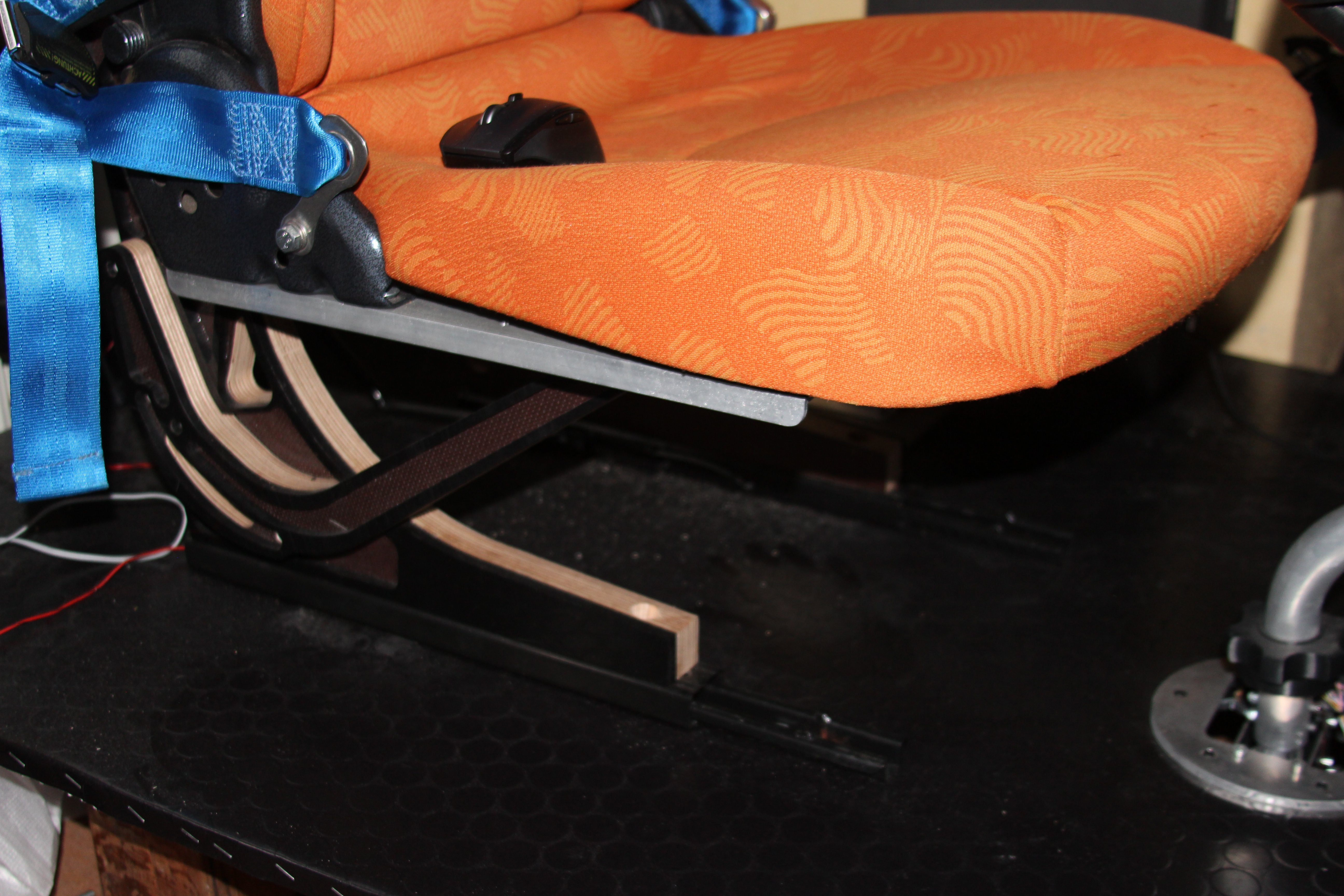
:pilotfly: I like its color, because orange is my preferred color. And it is a civilian EC-120 :music_whistling: And used Smart seats are really cheap, mine was 39,-€ + shipping. 1 day for disassembling, cleaning and mount it on my foot frames. -
Helicopter control mounting?
yogi149 replied to Mr.Fenestron's topic in PC Hardware and Related Software
Hi, can you tell something about the seats you would use? In my simpit I use a modified seat from a "Smart", which are really cheap at ebay. I made a mount frame which looks like the real EC-120 seat. the seat can be mount with simple connectors. I even can use the rail for adjusting.:music_whistling: In my opinion these seats are better for "heli-use" than racing seats.
-
Helicopter control mounting?
yogi149 replied to Mr.Fenestron's topic in PC Hardware and Related Software
@Wolf: do you mean horizontally mounted mechanic or horizontally stick tube? The most helicopters I know use an angled stick tube for ergonomic use. -
Helicopter control mounting?
yogi149 replied to Mr.Fenestron's topic in PC Hardware and Related Software
Hi, would a rig system like the monstertech be enough for you? That would not be a problem.:music_whistling: I used those profile systems when I made device housing and handling robots some years ago. Would it be ok, when my pedal- and cyclicmechanic would be mount on/under a platform on such a rig? -
Hi heloguy, at moment I connect the buttons I need to the arduino instead to the BBI. On the Arduino there will be some numbered pins assigned for programmed functions. Which button you choose will be according to your own taste. :music_whistling: At moment test phase is just delayed. (nearly before finishing:cry:) Some weeks ago our freelance assistant for production had to leave us, he had made himself too much stress and has thrown our schedule into disarray.:mad: Because of the stress, the quality of the products were no longer correct, and some tools became unusable. However, he did not want to go to a doctor to control his condition and so we decided for a separation. I myself had a heart attack two years ago and could not understand this behavior. To avoid stress again we have to reorganize our schedule, but we are on a good way. When the reorg is complete, I think that we can reach a delivery time of approximately 30 days.
-
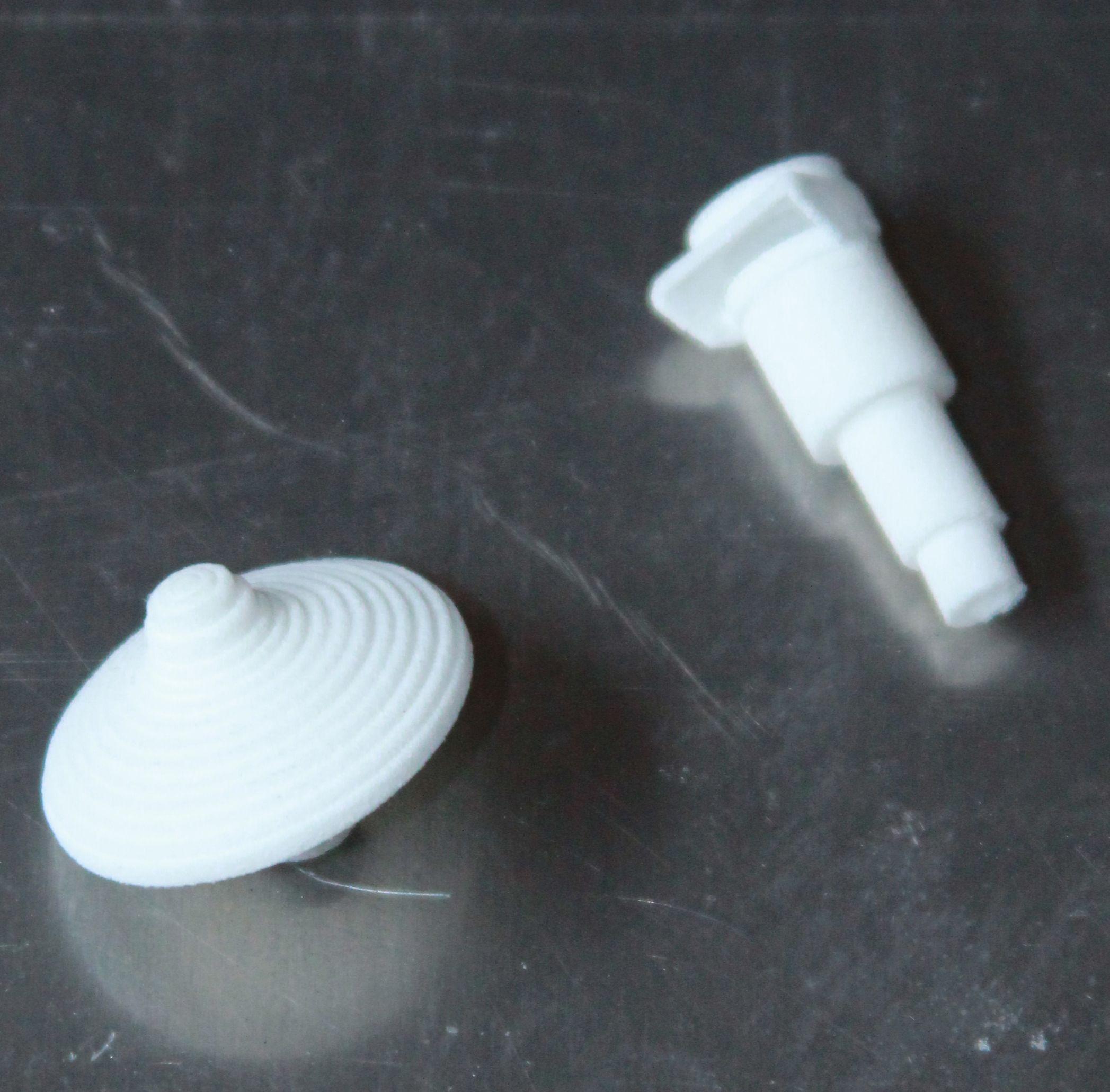
Hi, :music_whistling: yes, the coolie-hat is not like the original. But that can be changed. We got an original collective head and the next orders will get an better replica. If you want, I can send these 2 parts with your other order.
-
Hi Trip, do you mean the parts in the base? They are printed in ABS, and yes, they have visible print structure. All visible parts of our controls will be delivered in painted PA SLS print.
-
Hi Chic, this could be your version, 22° and 150mm shorter tube. The UH stick has no interior cable on the mounting end, so the tube can be adjusted to the seat height.
-
Hi, I do not think that space is any problem.:music_whistling: But I have to add some mounting holes for the board and the USB. Some hints where to make them? Top or side?
-
Hi, for the right distance I prefer the complete floor.:huh:
-
:cry: this is the enclosure for the collective.
-
Hi Trip, glad to know, that it finally arrives. I thought the customs officers were going to strike:music_whistling:, because all other packages show the same stop in Frankfurt at the customs.:cry: