NOALB
-
Posts
38 -
Joined
-
Last visited
Content Type
Profiles
Forums
Events
Everything posted by NOALB
-
Pretty minor error, but on pg 273 of the English manual the EPR pictured is the УР-117В with a 'В' at the top instead of our model with an 'О' at the top :music_whistling:
-
Sorry, but I really don't think this is correct. In your screenshot, the EPR indicator is marked with Cyrillic 'О', 'Н', and 'К', as in the standard Russian pit. These stand for "Ограниченный (взлет)" [Ogranichennyy vzlet] - Limited/Takeoff Power, "Номинальный (режим)" [Nominal'nyy rezhim] - Nominal/Maximum Continuous Power, and "Крейсерский (режим)" [Kreyserskii rezhim] - Cruising Power, respectively. In the English version provided by BST the EPR is labelled 'T', 'M', and 'C', presumably meaning Takeoff, Maximum (limited cruise), and Cruise. The limits of these power regimes are (in minutes): 6 Takeoff, 60 Max Continuous, and ∞ Cruise. Being between the 'О' and 'Н' on hover check is fine as long as that power isn't maintained past the specified 6min time limit. Above 2500m or 24°C, the EPR loses accuracy and the charts or N1/charts must be consulted to determine power settings. By the way, the dual engine tach needles both indicate N1 for their respective engines; there's no exact indication of N2 and it isn't something you really need to worry about anyway. The EPR is indeed the quickest way to determine your power setting, and the Rotor RPM Nr, Engine RPM N1, and PTIT gauges should be periodically scanned to ensure you're staying within limits; in general, stay between 93-97% Nr and below 910°C PTIT. Can't really give a good rule of thumb for N1, but you kind of get a feel for it.
-
Yes, first thing to check is that the engines are running within the limits specified on pg. 236 of the manual. Make sure you give the engines time to spool up when pulling collective, or you could experience loss of generators when Nr (rotor RPM) droops below around 86%. Also be sure that you manually activate the left engine anti-icing if the РИ-65 gives an icing warning (also indicated with a flashing red 'ОБЛЕДЕН' annunciator under the anti-ice control panel)(activating left engine anti-ice immediately isn't realistic procedure, but AFAIK there is no downside to doing this with our model). As a side note, don't forget to switch on pitot heat as well; I find it's usually best to activate pitot heat as part of startup unless you're certain the entire flight will take place outside of icing conditions. As stated, the OAT gauge is mounted on the windshield underneath the copilot's weapon/bomb/payload control panel, illustrated on pg. 64 of the manual. If you're unfamiliar or uncomfortable with the Russian РИ-65 messages, you can switch to English by going to Options > Gameplay > Avionics Language. If it's helpful, here's a table containing the transcripted warnings in Russian (РУ), my best attempt at a somewhat-phonetic transliteration (TR), and the English translation (EN). Note I do not speak Russian, so the transliterations are probably quite a bit off. [TABLE] РУССКИЙ | TRANSLITERATION | ENGLISH ПОЖАР В ОТСЕКЕ ЛЕВОГО ДВИГАТЕЛЯ|POZHAR V OTSEKE LYEVAGA DVIGATELYA|FIRE LEFT ENGINE ПОЖАР В ОТСЕКЕ ПРАВОГО ДВИГАТЕЛЯ|POZHAR V OTSEKE PRAVAGA DVIGATELYA|FIRE RIGHT ENGINE ПОЖАР В ОТСЕКЕ ГЛАВНОГО РЕДУКТОРА|POZHAR V OTSEKE GLAVNAGA REDUKTARA|FIRE MAIN TRANSMISSION ПОЖАР В ОТСЕКЕ ОБОГРЕВАТЕЛЯ|POZHAR V OTSEKE OBOGREVATILYA|FIRE KO-50 ОБЛЕДЕНЕНИЕ|OBLIDINENIYE|ICING ОТКАЗАЛИ НАСОСЫ ОСНОВНЫХ ТОПЛИВНЫХ БАКОВ|OTKAZALI NASOSY OSNOVNYKH TOPLIVNYKH BAKOV|MAIN FUEL TANK PUMP FAILURE ОТКАЗАЛ НАСОС РАСХОДНОГО БАКА|OTKAZAL NASOS RASKODNAGA BAKA|SERVICE FUEL TANK PUMP FAILURE ОТКАЗАЛА ОСНОВНАЯ ГИДРОСИСТЕМА|OTKAZALA OSNOVNAYA GIDROSISTEMA|MAIN HYDRAULICS FAILURE ОТКАЗАЛ ПЕРВЫЙ ГЕНЕРАТОР|OTKAZAL PERVYY GINIRATOR|FIRST GENERATOR FAILURE ОТКАЗАЛ ВТОРОЙ ГЕНЕРАТОР|OTKAZAL VTOROY GINIRATOR|SECOND GENERATOR FAILURE ВЫКЛЮЧИТЬ ЛЕВЫЙ ДВИГАТЕЛЬ|VYKLUCHIT' LYEVYY DVIGATEL'|TURN OFF LEFT ENGINE ВЫКЛЮЧИТЬ ПРАВЫЙ ДВИГАТЕЛЬ|VYKLUCHIT' PRAVYY DVIGATEL'|TURN OFF RIGHT ENGINE ОПАСНАЯ ВИБРАЦИЯ ЛЕВОГО ДВИГАТЕЛЯ|OPASNAYA VIBRATSIYA LYEVAGA DVIGATELYA|LEFT ENGINE VIBRATION ОПАСНАЯ ВИБРАЦИЯ ПРАВОГО ДВИГАТЕЛЯ|OPASNAYA VIBRATSIYA PRAVAGA DVIGATELYA|RIGHT ENGINE VIBRATION НЕИСПРАВНОСТЬ РЕДУКТОРА|NIISPRAVNOST' REDUKTORA|TRANSMISSION MALFUNCTION АВАРИЙНЫЙ ОСТАТОК ТОПЛИВА|AVARIINYY OSTATOK TOPLIVA|EMERGENCY FUEL REMAINING БЛОК РИ-65 ИСПРАВЕН|BLOK RI-SHIZDISYAT-PYAT' ISPRAVEN|RI-65 WORKING[/TABLE]
-
Apologies if it's been reported already (or is just on my end) but couldn't find anything in search. When creating a trigger with a RADIO TRANSMISSION action in the ME, the NAME argument is left as nil unless something is entered (or entered and deleted) in the NAME: field. Leaving it as nil seems to break its functionality. To reproduce: Create a new trigger and add a 'RADIO TRANSMISSION' action. For me, the default values produce the following string: RADIO TRANSMISSION (, , false, Off, 124, 100, nil) now put the cursor in the 'NAME' field, enter a character, and delete it. Note that nil is replaced with an empty string value. If you test the mission before and after replacing the nil value, you can see that leaving the field as-is breaks the transmission. Looking at the mission file in the resulting .miz shows several changes occurring when the fix is done, but I have no idea if the value being nil is what causes the issue or if something else is being updated when this is done.
-
I assumed this would be trivial, but no, it seems there actually might be a bug affecting a certain aspect of this... To work around it, ensure that when setting up the RADIO TRANSMISSION options, the NAME: field is either filled, or filled and then cleared. If you look at the string it's generating in the actions box, the goal is to make sure that nil at the end is either removed or replaced with a legal value. I̶'̶l̶l̶ ̶e̶d̶i̶t̶ ̶t̶h̶i̶s̶ ̶p̶o̶s̶t̶ ̶w̶i̶t̶h̶ ̶a̶ ̶l̶i̶n̶k̶ ̶t̶o̶ ̶t̶h̶e̶ ̶b̶u̶g̶ ̶r̶e̶p̶o̶r̶t̶ ̶a̶f̶t̶e̶r̶ ̶i̶t̶'̶s̶ ̶s̶u̶b̶m̶i̶t̶t̶e̶d̶.̶ https://forums.eagle.ru/showthread.php?t=206921 Anyway, there's a few more problems besides just the bug. Use AM modulation, loop On (unless you want the transmission to play only once), and check that you're entering a value using the correct units for the frequency (900 kHz = 0.9 MHz). If you're getting sound but the ADF needle isn't working, check these things: -СПУ-7 panel is set to 'РК 1' to ensure that you're indeed listening to the АРК-9 and not a different radio -АРК-9 is set to 'КОМП.' to enable the ADF. 'АНТ.' is antenna, which is audio without ADF, and 'РАМ.' is loop, which allows you to find the direction of the transmission manually. DF without the A! -The АРК-СВ/АРК-УКВ switch below the pilot's gyrocompass is switched to 'АРК-СВ' Apologies if those are obvious, but it's strange that you would be getting audio without ADF unless the signal's very weak.
-
Yeah, I've looked into this back when I was on the Steam version; I particularly appreciated how with the overlay active it was still possible to use my media keys to advance tracks and whatnot on my audio player. Speaking of which, even though the InputEvents.lua file seems to define the media keys, DCS doesn't seem to detect them at all, making them utterly useless when ingame (at least for me). +1 because it really should be an option to change/unbind.
-
Hah, I've done the same thing myself :D :doh: If you don't have any custom templates you want to save, one way would be to delete the templates.lua file under your Saved Games\DCS\MissionEditor folder. If you do have custom templates, the default templates can be found in a file with the same name under DCS\MissionEditor\data\scripts. Copy lines 3-107, starting with the line ["SA-10 (S-300PS) site"] = and paste it just after the first opening brace in the templates.lua file in your Saved Games.
-
Some help with creating a mission
NOALB replied to scampaboy's topic in DCS: Mi-8MTV2 Magnificent Eight
I can't speak regarding the compatibility of CTLD or any mods, but the method described in that guide works fine for me. It's a bit more complex than it needs to be, though, and it seems to be missing a trigger to stop the transmission if the "station" is destroyed (which is something I assume you might want). My method: 1: Create the trigger zone and place the center on the station. The radius seems to be completely meaningless in this case unless you're using it for something else since the wattage of the broadcast will be what affects the reception range (just make the radius as small as possible so it doesn't obscure your editor as much) 2: Create a MISSION START trigger (name it whatever you want) with no conditions and one action: -ACTION: RADIO TRANSMISSION -FILE: [audio file name] -ZONE: [zone name] -MODULATION: AM -LOOP: On (or as desired) -FREQ, MHz: 124.1 -POWER, W: As desired, or just at the maximum value if you don't care about limited reception range -NAME: As desired (but this value is important! Don't leave it blank!) 3: Create a ONCE, NO EVENT trigger with one condition: -TYPE: UNIT DEAD -UNIT: [name of your broadcast station unit] and one action: -ACTION: STOP RADIO TRANSMISSION -NAME: [name of your broadcast from the previous step] A couple important things to remember: Make sure you switch the pilot's gyrocompass to АРК-УКВ mode (the copilot's gyrocompass can only monitor the АРК-9). The АРК-УД SAR radio seems to only be able to demodulate AM signals. If the transmission is using FM, it'll still pick up the signal and the УП light will illuminate, but it'll only act as a homing beacon and you won't hear anything when switching the СПУ-7 to РК 2. If you want it to work this way, you could simply have the АРК-УД do the work of homing while using the Р-863 to listen to the broadcast (while switched to ЧМ). (I was also thinking it may be possible to have a nice static effect when the station's destroyed by turning off the squelch on the 863, but it doesn't seem to do anything when on the frequency, even after the transmission stops. Possible bug found?) -
All "pod" type weapons (GUV 622/624 and 800, as well as UPK pods) produce no firing audio when mounted on the right (5 and 6) hardpoints; this doesn't seem to be the case for rockets and bombs. I'm on open beta branch version 2.5.0.15365. To replicate: load pods on hardpoints 5 and 6 only (asymmetric loadout) and fire (alternatively, use a normal symmetric loadout and switch off left GUV CBs). I didn't get any audio from inside cockpit or external view. Yes, I know it's unrealistic to do this and not a practical problem, but just want to be sure the devs are aware. I also understand if this is actually an intentional compromise to reduce the audio processing load. Can anyone else confirm that it's not just my system? (On a side note, I noticed that the 622/624 pod is listed as the "GUV YakB GSHP" in the ME rather than the expected 'GShG' consistent with the manual and Cyrillic 'ГШГ'. Just a typo or something I'm missing?)
-
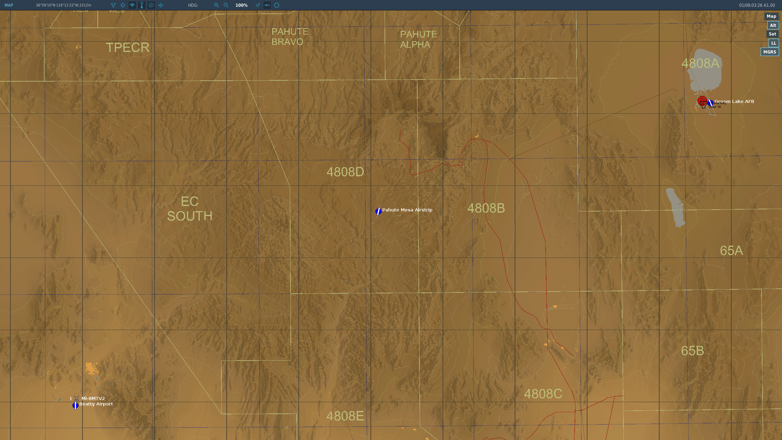
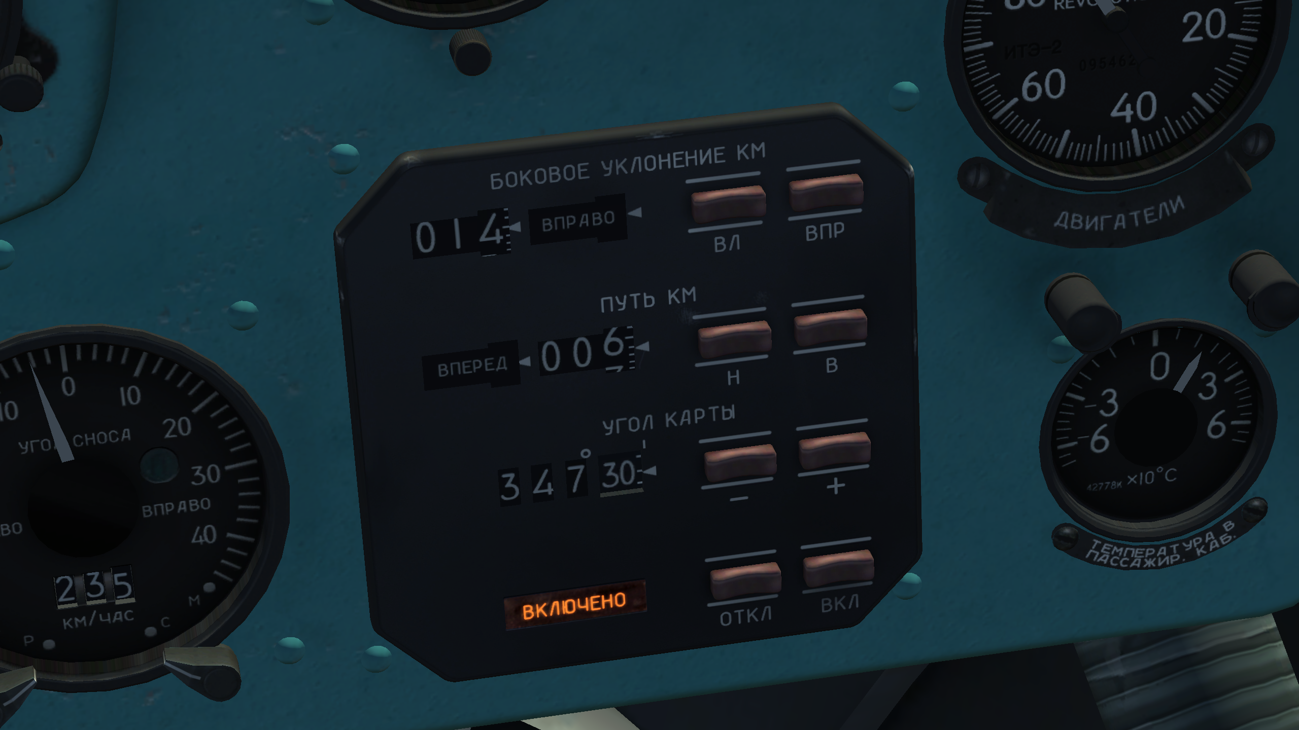
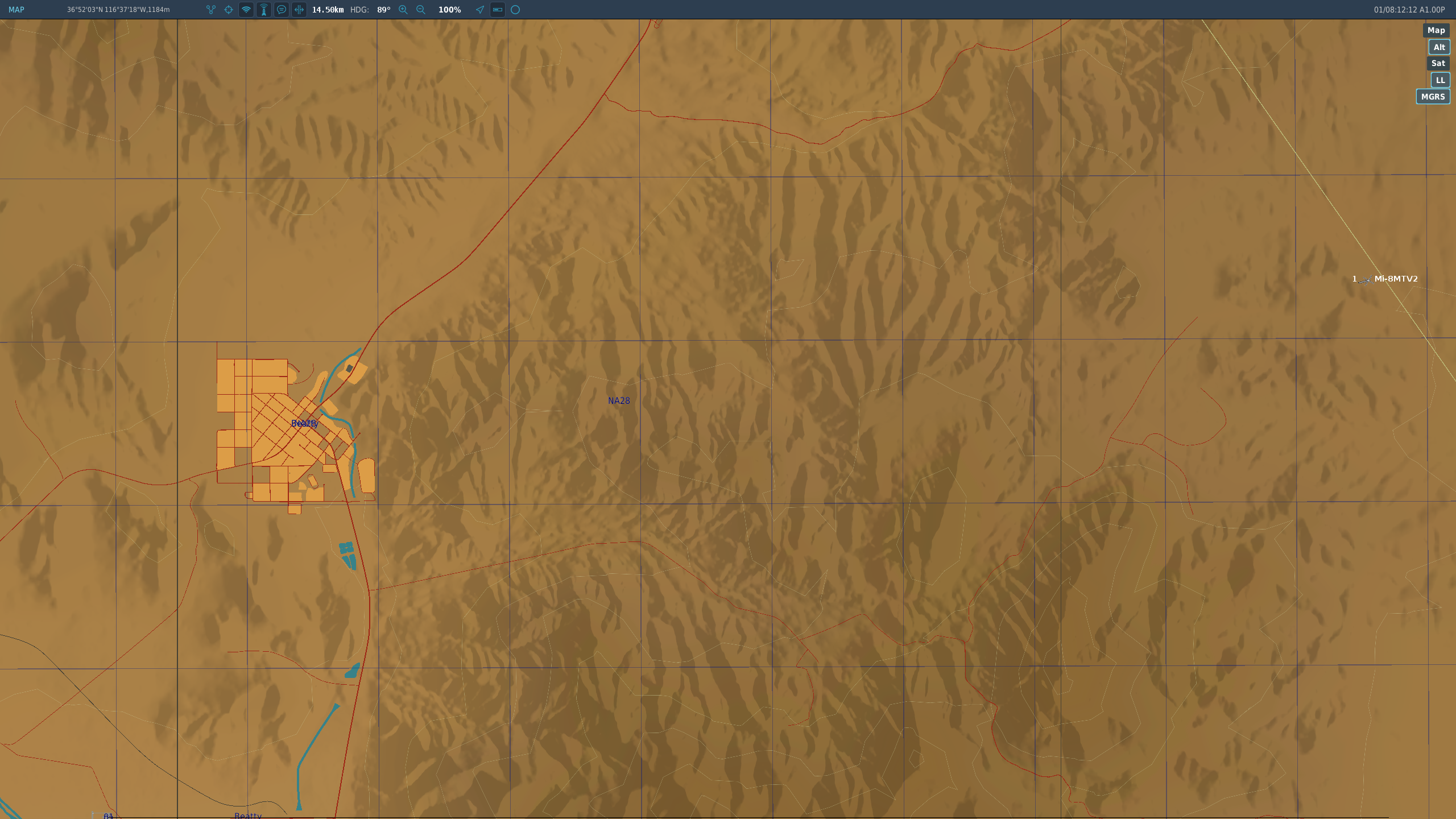
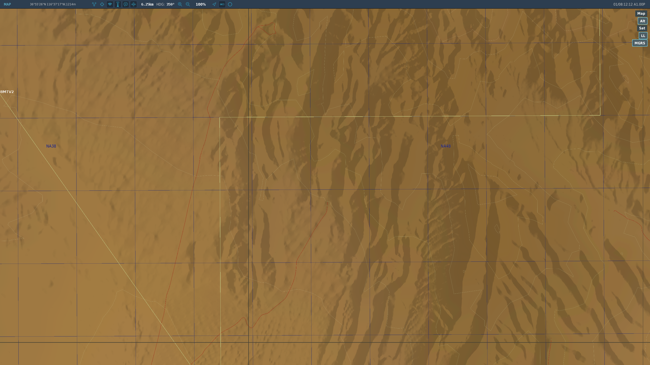
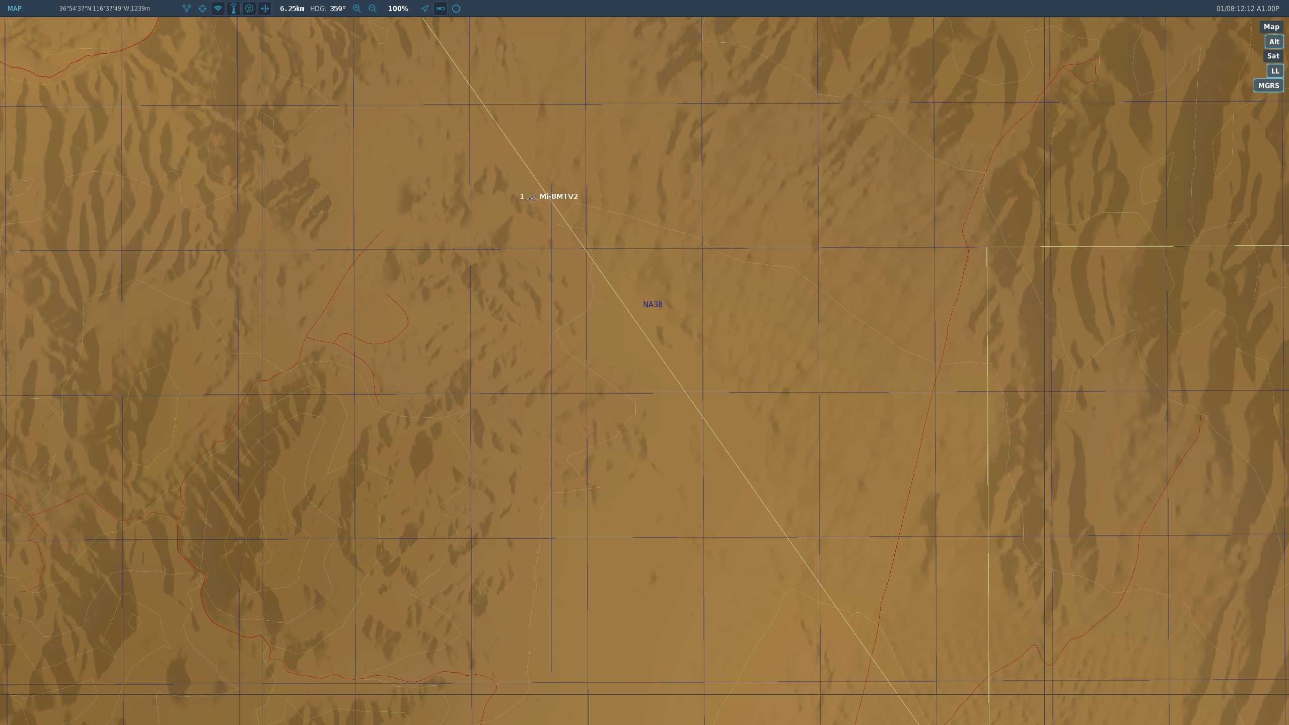
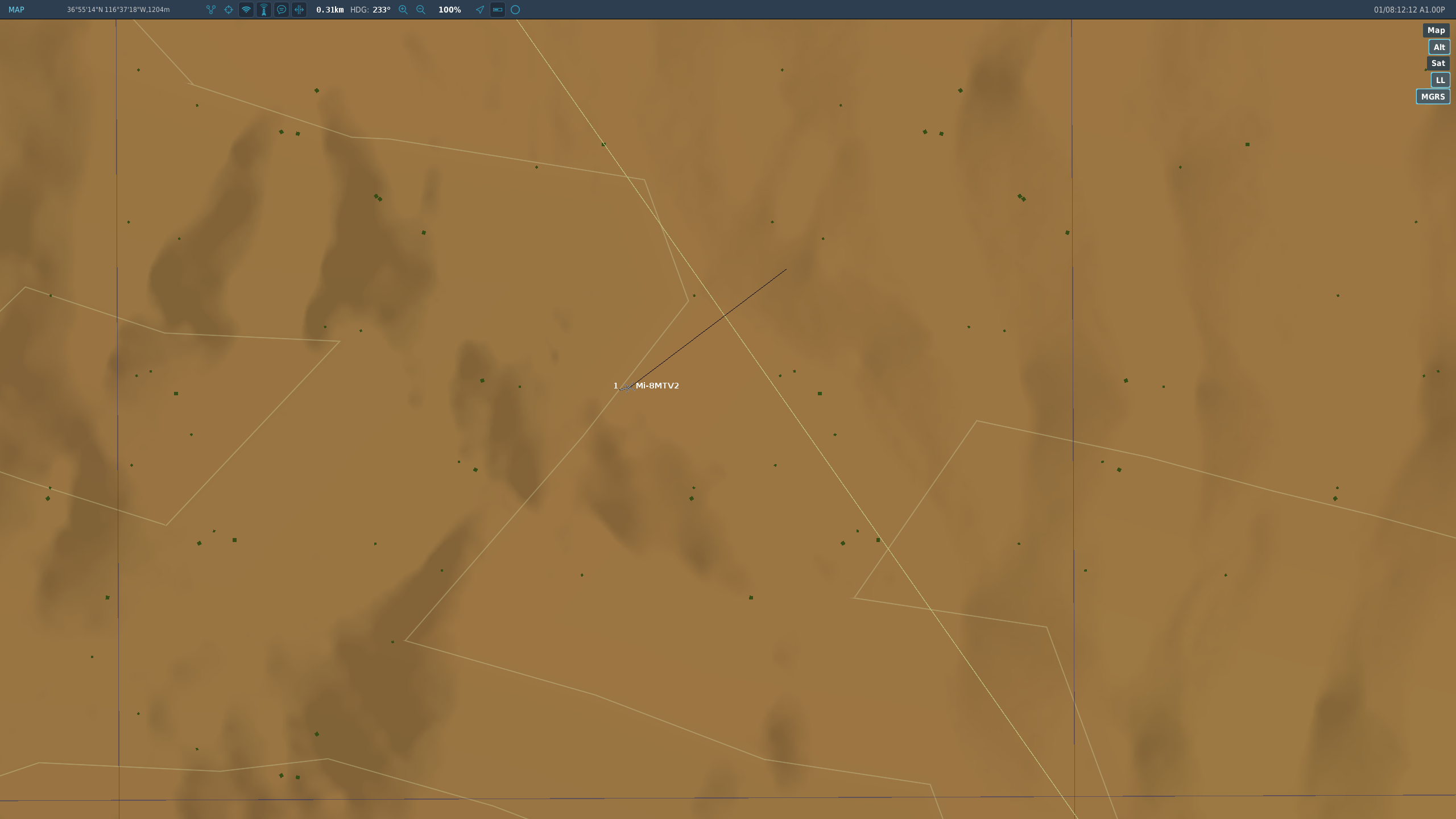
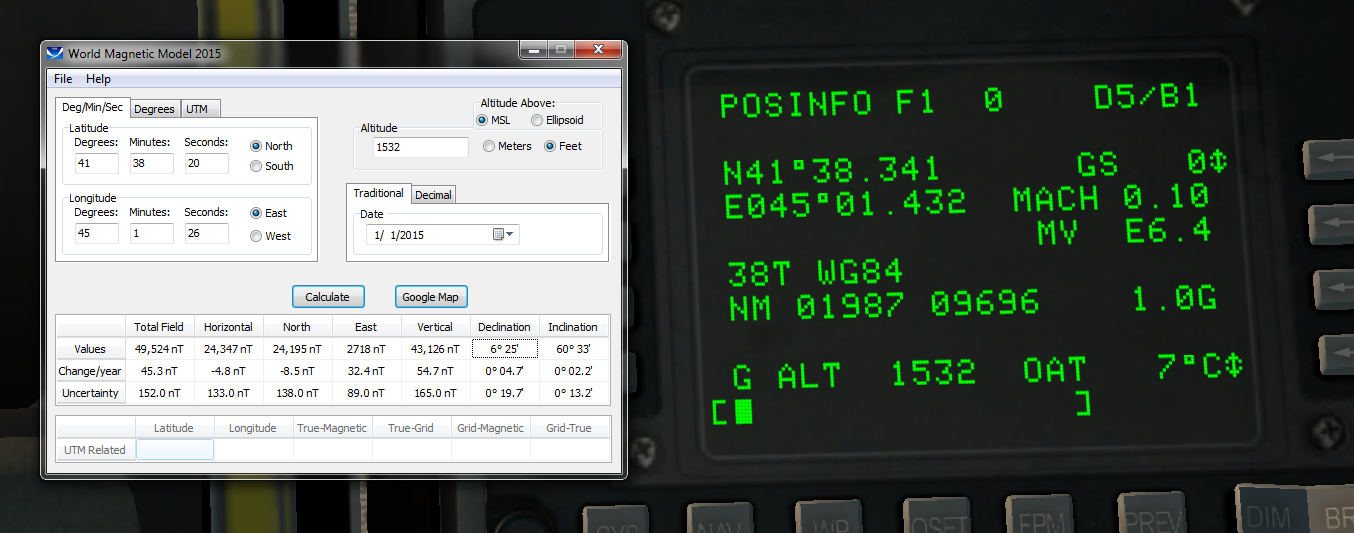
I'm going to go into depth with a different technique (apologies if it's too off topic), but to answer your question, the most efficient way to navigate by waypoints is to turn off, then set up the ДИСС-15 for the next leg of the route as soon as your current waypoint comes into sight. That way, you can simply push the ВКЛ button as you overfly the waypoint and immediately start heading towards the next one. I'll assume you're already familiar with the basic operation of the ДИСС-15, but if not, here is one excellent resource: http://www.mudspike.com/how-to-use-the-doppler-navigator-in-dcs-mi-8mtv2/ I want to focus on the "GRID" method described in that guide, because it has the advantage of allowing one to arbitrarily determine their location even if they aren't following a particular course. This makes it very useful for combat, reconnaissance, and generally any situation in which you may not be following a predetermined route or may heavily deviate from it. Also, the ДИСС-15 can be left alone after takeoff (unless using a fixpoint). My method uses a slight alteration, though: course angle is set to true north rather than magnetic north to allow easy use with the F10 map. This lets the ДИСС-15 be used much like an INS. Before that, I want to quickly discuss magnetic bearings in DCS. As you know, all navigation using the Mi-8 is done relative to magnetic bearings, which requires knowledge of the local magnetic declination of the area if you want any significant accuracy. Contrary to the Caucasus approach plates which all claim a local declination of 6° (for 2010, no less!), DCS actually features a detailed implementation of the World Magnetic Model to simulate magnetic variation; the coefficient files can be found at DCS\Data\MagVar\COF. Demonstrated here courtesy of the A-10's CDU: As mentioned in the linked guide, this unfortunately seems to be the easiest way to get the declination of a specific area (obviously a problem for those without the A-10). Also shown in the linked guide is a declination map, the latest of which may be obtained here: https://www.ngdc.noaa.gov/geomag/WMM/data/WMM2015/WMM2015_D_MERC.pdf There's two problems with this, however: the map isn't very precise, and the data is only for 2015 and later. Even the calculator shown in the above image is only designed to work with the 2015 data. I haven't found a simple method of getting precise declination figures without the A-10, but maybe someone else could chime in with an answer. Why's this all so important? Well, the Grid method has another advantage: it can make better use of a precise declination figure. The F10 map ruler usually used to get bearings for navigation is only precise to the nearest degree. If the course angle drum of the ДИСС-15 is set up using a precise declination figure (since it accepts minutes as well as degrees), the added precision can make a significant difference for long flights. With that in mind, here's how to use the Grid method: The F10 map, ruler, and digital counters of the ДИСС-15 will be used to determine location. I'll start with an example: For demonstration purposes, we'll be flying from Beatty Airport to Area 51. The reference point will be the Beatty Airport apron (giving us 1 quadrant to work in). The helicopter will be shown on the map to illustrate how the technique works (obviously this wouldn't be the case in a practical scenario). Because the reference point is our starting point, the lateral deviation and distance counters will be left alone. 12.5° is a good approximation of the declination over our expected flight area over the NTTR, so we'll enter 347°30' as our course angle. This is the only time we need to mess with course angle using the Grid method! Now we push ВКЛ to start operating the ДИСС-15, checking that the ДИСС ОТКАЗАЛ annunciator is not illuminated. Note that a nearby landmark can also be used as the initial fixpoint, but this is unnecessary since we know our starting location with a high degree of accuracy. Takeoff! We must be careful not to exceed the ДИСС-15's attitude limits of 7° pitch or 30° bank, or the quality of the navigation solution will be degraded. This is another reason why you may wish to start operating the system at an initial fixpoint instead. After stabilizing at altitude, let's take a reading (while paused for demonstration): About 14.5 ВПРАВО (right) and 6.25 ВПЕРЕД (forward). Since we're working in 1 quadrant, we can ignore the directions and interpret the values as x and y on a Cartesian coordinate system. Next we open the F10 map and use the ruler to draw lines corresponding to the coordinates (once again, pretend the aircraft isn't visible!). Since the ruler seems to lack the ability to draw lines at vertical and horizontal angles, we use the edge of the screen as a guide: Drawing the line (look carefully at bottom edge of image)... The resulting line Drawing the vertical line (on the left edge, not visible this time)... The resulting line, again About 310m off. Worse than I'd prefer, but we can always create a fixpoint to regain accuracy. We'll change course and set our next waypoint to be the Pahute Mesa Airstrip. Note the advantage the Grid method proviedes here: we can change our route at will without needing to reset the ДИСС-15, while still being able to arbitrarily determine our position along the way. Oh no! Our navigator's been resting on the ВЛ button! We'll have to use the Pahute Mesa Airstrip as a fixpoint. Fortunately, it's just up ahead. Taking a fixpoint: 1: Select a landmark! Hint: the satellite layer of the F10 map is very useful for this 2: Turn off the ДИСС-15 by pressing the ОТКЛ button 3: Enter the x (lateral deviation) and y (distance) coordinates of the fixpoint in relation to the reference point (place the fixpoint along the side of the screen and reference point along the bottom to get straight lines) 4: As you overfly the fixpoint, push ВКЛ to reengage the system. You now have your precision back! Note: The Mi-8 crew died on the way to Area 51. They didn't get clearance to enter the airspace. Let's review: Step 1: Pick a reference point to be used for the duration of the flight; this is somewhat like a bullseye. A simple choice is the starting airfield, but this may not be as precise as other candidates. There's a few considerations here: —The reference point needs to be easy to remember. You can use a Mark Label if you think you'll forget (but this introduces a difficulty later on) —The reference point should be easily located even when zoomed out. You'll be drawing lines using the ruler from this point, so make sure it isn't too small! —The reference point will be used as the origin of a Cartesian coordiate system; you can therefore choose to work in 1 or more quadrants. If you would like to work with only 1 quadrant (so you don't need to pay attention to whether the ДИСС-15 is indicating ВЛЕВО or ВПРАВО, for example) choose a reference point which contains your entire likely flight area in that quadrant (e.g. if you want to work in quadrant I only, choose a reference point further southwest than any location you will likely be at) —You can locate yourself more precisely if you place the reference point in the middle of your likely flight area, because you won't need to zoom the map out as far. You will have to pay attention to quadrants, though Step 2: Determine your location relative to the reference point and enter the coordinates into the system. If you can't determine your starting location precisely, pick a nearby landmark and enter those coordinates instead (this can be done in flight as well, though it's easier on the ground). Once again, a few considerations: —If your starting location is the reference point, you can skip this step —If you intend to perform a running nosewheel takeoff or other high-performance takeoff maneuver requiring excess pitch and/or bank angles, opt for the landmark as a starting fixpoint. This way, you won't immediately have to take the attitude limitations of the ДИСС-15 into consideration —If you're performing a ground taxi or hover taxi below 2m, the ДИСС-15 will not be operable during this time and you should instead opt for a landmark fixpoint (the center of the runway or a radio NAVAID station past the runway is a good choice) —If there's no suitable landmark visible from the cockpit, use the F10 map's satellite view to locate one Step 3: Activate the ДИСС-15 system by pressing the ВКЛ button. If you're fixing on an initial point instead, activate the system as you overfly it. Watch for the ДИСС ОТКАЗАЛ annunciator as you take off; this indicates a possibly degraded naviation solution and you should seek to take another fixpoint as soon as possible You are now ready to go! Determine your location and take new fixpoints as needed. Addendum---- For those very serious about determining their location precisely while moving, the Mi-8 is not for you! Just kidding, but you've probably noticed that my demonstration only showed the result of measuring coordinates with the sim paused. If you want to get an accurate result while moving, grab a calculator; the process is much more complex: To find your location at a specific time: Maintain constant speed and heading (use all autopilot channels). THIS IS CRITICAL! Prepare to start stopwatch. Read DISS coords and start stopwatch as quickly as possible to minimize error, then mark location (simply leave the ruler line intact) Divide ground speed by 3600 to obtain speed in kps. Record result. Read heading on gyrocompass, add declination, and subtract left drift angle (or add right drift angle). Record result. (Note: "time" here refers to time in seconds, e.g. 1m30s = 90s) Look at the stopwatch and choose a time about 30s in the future (to allow time to do the following): -Multiply said time by result of first calculation to get distance travelled -Using ruler on map, draw line from marked location using bearing of second calculation to obtain predicted location Perform these tasks Wait until stopwatch reaches designated time. You should now be at the predicted location. Laconic version: —Stabilize speed/heading —RAPIDLY read coords & start stopwatch —Mark location [Ground Speed] / 3600 -> s [Magnetic Heading] + [Declination] ± [-L or +R Drift Angle] -> b [Elapsed Time] + 30 -> t t * s -> d Mark map (b bearing for d km) Wait until t to arrive at location. As continuous calculations: Distance: ([Ground Speed] / 3600) * [Elapsed Time] + 30 Bearing: [Magnetic Heading] + [Declination] ± [-L or +R Drift Angle]

-
More axes and rotary switches please.
NOALB replied to Lixma 06's topic in DCS: Mi-8MTV2 Magnificent Eight
You can add the following line to your joystick default.lua file to add an axis control for the PKV elevation knob: {action = 3003, cockpit_device_id = 47, name = _('Sight Limb Knob')}, (Note that it must be within a set of join(res.axisCommands,{}) brackets, and OUTSIDE of the join(res.keyCommands,{}) block, e.g. join(res.axisCommands,{ {action = 3003, cockpit_device_id = 47, name = _('Sight Limb Knob')}, }) join(res.keyCommands,{ --All the normal joystick commands here }) (There's also a join(res.axisCommands,{}) block near the end of the file, but I like to keep my custom commands at the top to keep things tidy.) There are several caveats to this, though—the axis is really only meant to be manipulated as a clickable cockpit element, so binding it as an axis lets it elevate about twice as high as it's supposed to go (as well as about 25% lower than otherwise able) because the clickabledata.lua file initializes the axis as follows: elements["PTR-PKV-ROTARY"] = default_axis_limited(_("Sight Limb Knob"), devices.PKV, device_commands.Button_3, 855, 0.0, 0.1, false, false, {0, 0.807}) This means that the axis limits range from 0 to 0.807 as a clickable cockpit control, but unfortunately when initialized in default.lua, the limits are set as -1 to 1 (I haven't figured out how to set limits on the axis in default.lua). You can work around this somewhat by using Axis Tune to make it an Inverted Slider with a Saturation Y of 50, but the downwards overtravel remains. This line can be added to control the sight brightness knob on an axis: {action = 3001, cockpit_device_id = 47, name = _('Sight Brightness Knob')}, If you apply the same Axis Tune settings as I suggested for the PKV elevation knob, it should work perfectly. I don't use either of these myself, but I have found this to be a particularly useful command (to be added in the join(res.keyCommands,{}) block): {down = 3003, value_down = .211434, cockpit_device_id = 47, name = _('Sight Limb Knob Index'), category = _('PKV')}, This lets you return the PKV elevation to the red index mark corresponding to the weapon boresight. Very useful when making close range follow-up shots in an attack run, or just as a default setting. You may notice that the arrows don't line up perfectly when using the command, but just trust me on the accuracy of that number ;) Okay, for anyone who's curious, check page 317 of the manual where it says [TABLE]Elevation knob red index corresponding to (mils)|52.4[/TABLE] Divide 0.807 by 200 (adjustment limit in mils) to get 0.004035 (one mil), then multiply by 52.4 to get 0.211434, the exact value of the index mark. You can use the same method to add commands for other commonly-used elevation settings. And I'm not sure exactly what you mean by 'rotary' commands. Like a button you can push repeatedly to cycle through all the switch positions?- 1 reply
-
- 1
-

-
I noticed this oddity too when I started using the '8. Your post reminded me to see if I could do anything about it, though; thanks :D If you haven't figured it out yet (I had to wait for the registration, sorry) the file in question you'll want to mess with is at DCS\Mods\aircraft\Mi-8MTV2\Views.lua At line 9 here: limits_6DOF = {x = {-0.200000,0.400000},y ={-0.200000,0.25000},z ={-0.650000,1.0},roll = 90.000000}, replace z = {-0.650000,1.0} with z = {-1.0,0.650000} or just use the JSGME-ready .zip here. Fixing this breaks the integrity check, however... I'm assuming when the file was created someone accidentally switched the values around, since the head movement boundary to the right is ludicrous (or perhaps that's intentional to accommodate snap view users?). Mi-8 Head Movement Fix.zip