lesthegrngo
-
Posts
1245 -
Joined
-
Last visited
Content Type
Profiles
Forums
Events
Everything posted by lesthegrngo
-
Very nice! I have to ask how smooth the movement of the pointers is using servoes as it would certainly be interesting to see if it improves on the rather jittery movement of the stepper motors I am currently using. I also like the geared actuation of the fuel quantity gauge, I was thinking that I would have to go that route and seeing it done gives me motivation to go that route. Cheers Les
-
Thanks! Les
-
What button caps did you use with those? cheers Les
-
All, with respect to using individual LCD or OLED displays for the individual lines as discussed above, that is exactly what I did in the end If you take a look at the third post in this thread you can find the sketch that make 3 0801 LCD modules work together so that they can be placed exactly where you want. There are two things to look out for, one being that the 0801 LCD modules (at the current time) are not available with white text on a black background, the other being that using three LCD displays off one arduino will mean that you have to supply 5v to the LCD modules otherwise they will become dim. The 5v supply can be common with the arduino. Les
-
It will work on either; essentially it will print each text string along the row, staring at the leftmost position you specify. For example, if you specify a four character text to start printing at zero, then a ten character text string to start on the same row at position six you will have a total text width of 16 characters like this xxxx__xxxxxxxxxx. If you use a 16 x 2 display it will fit exactly, and with a 20 x 2 it will print fine with four blank extra characters to the right, so it will work fine. You could choose the starting point of the text strings to make the text appear in a different position to either separate the strings or position them in the centre However if your display is say 12 x 2, if you try to print both text strings on the same row at the positions above, it will work but the last four characters of the ten character string will be off the end and so won't be displayed. You could specify that the secont text string prints from position 2 so that it fits, but it would overwrite the last two charcters of the first string, plus there would be no space between the two text strings. To summarise, ideally you select an LCD module that is slightly wider than the total number of characters you want to display on one line. Cheers Les
-
My suggestion is to keep it simple to start with - do one LCD panel with one arduino, so that you get to see how it all connects. After that you will see that in most cases, it is just the same over and over again, and you will realise it is pretty much modular. There are a couple of points that may help simplify things though. A lot of the LCD modules come with 16 pins that you connect up, although from memory you end up using only about 10 of them. However in this form the wiring is a lot more complcated. That's where you should get either an LCD module that is quoted as being 'I2C', or if that is not available you get a PCF8574 board. This is simply an adapter that plus girectly to the LCD module pins and converts the connections to four pins, simplifying the connections massively. Essentially it converts the LCS module to 'I2C'. Since two of those four pins are VCC (+5v) and GND, which are easy to connect and pretty much anything you connect to an arduino will connect to the +5v and GND, that means you only have to worry about the other two connections. They can be called different things, but SDA and SCL are common, but you may see them as DIN, or Data and Clock. The fact of the matter is that with these two pins, they almost invariably connect to the A4 and A5 pins respectively, but if you get them wrong all that happens is that the LCD will light up with no data. It (in my experience at least) does not damage the LCD module. Obviously VCC and GND are more touchy, but even so I have not managed to damage an LCD module by incorrectly wiring these, but maybe I was just lucky. I have however managed to ruin a PCF8574 board by getting the power connections wrong. If you connect up a module that has at least 16 columns and two rows of character blocks and then load up the sketch pasted in further down below that is highlighted in a blue box, you will be able to get it to work with DCS BIOS for the A10C if you connect the Arduino to the PC via USB. I have repeated the sketch just below here in plain text with some annotations to help you understand, please note that this is for and LCD module using a PCF8574 adapter. #include <Wire.h> #include <LiquidCrystal_PCF8574.h> #define DCSBIOS_IRQ_SERIAL #include <DcsBios.h> LiquidCrystal_PCF8574 lcd(0x27); // set the LCD address to 0x27 for a 16 chars and 2 line display int show; This fisrt section above is telling the Arduino how to set up and reference different 'libraries' (basically sub-programs that run standard stuff for you) plus also tell it what LCD module type it is looking at. The PCF8574 part is like a translator (oversimplified but it serves to help understanding) that means that it can use the PCF board to communicate just using the two pins instead of all the others void onCmscTxtJmrChange(char* newValue) { lcd.setCursor(0, 0); lcd.print(newValue); } DcsBios::StringBuffer<8> cmscTxtJmrBuffer(0x1096, onCmscTxtJmrChange); This bit is saying "go and get the data called "CmscTxtJmr" (which is the CMSC Jammer text) and then print those characters starting at column 0 (the one to the far left of the module) and row 0 (the topmost row). DCS bios is set up to send the data in a string of standard format ASCII characters that the LCD module accepts void onCmscTxtChaffFlareChange(char* newValue) { lcd.setCursor(4, 0); lcd.print(newValue); } DcsBios::StringBuffer<8> cmscTxtChaffFlareBuffer(0x108e, onCmscTxtChaffFlareChange); This bit is saying "go and get the data called "CmscTxtChaffFlare" (which is the CMSC Chaff adn Flare text) and then print those characters starting at column 4 (the fifth one from the far left of the module, remembering that '0' is the first one) and row 0 (the topmost row). void onCmscTxtMwsChange(char* newValue) { lcd.setCursor(0, 1); lcd.print(newValue); } DcsBios::StringBuffer<8> cmscTxtMwsBuffer(0x12b0, onCmscTxtMwsChange); This bit is saying "go and get the data called "CmscTxtMws" and then print those characters starting at column 0 (the one to the far left of the module) and row 1 (the second row from the top, row 0 being the first). void setup() { lcd.begin(16, 2); lcd.clear(); DcsBios::setup(); This is saying to initialise the LCD module, and wipe whatever is on the LCD screens } void loop() { DcsBios::loop(); lcd.setBacklight(255); } Finally this says once it has done the operations above (in this case print the text, but it could be something else in different units) then go back to the start and redo it, and in this way it checks the data again and displays it, so if the data has changed it will wipe the old data and replace it with the new. Finally here is the complete unadulterated sketch for you #include <Wire.h> #include <LiquidCrystal_PCF8574.h> #define DCSBIOS_IRQ_SERIAL #include <DcsBios.h> LiquidCrystal_PCF8574 lcd(0x27); // set the LCD address to 0x27 for a 16 chars and 2 line display int show; void onCmscTxtJmrChange(char* newValue) { lcd.setCursor(0, 0); lcd.print(newValue); } DcsBios::StringBuffer<8> cmscTxtJmrBuffer(0x1096, onCmscTxtJmrChange); void onCmscTxtChaffFlareChange(char* newValue) { lcd.setCursor(4, 0); lcd.print(newValue); } DcsBios::StringBuffer<8> cmscTxtChaffFlareBuffer(0x108e, onCmscTxtChaffFlareChange); void onCmscTxtMwsChange(char* newValue) { lcd.setCursor(0, 1); lcd.print(newValue); } DcsBios::StringBuffer<8> cmscTxtMwsBuffer(0x12b0, onCmscTxtMwsChange); void setup() { lcd.begin(16, 2); lcd.clear(); DcsBios::setup(); } void loop() { DcsBios::loop(); lcd.setBacklight(255); } The description above is a fairly loose description of how it works to try and help beark it down into more digestable packets, and is probably not exactly how some of it works. However it was like this that I managed to get my head around it, and if you are patient and methodical and start small you can get there. Oh, and remember to install DCS BIOS, I know that my Steam version of DCS way back when I started didn't want to know, but it works fine with a non-Steam version. Not sure if that is still the case. I also need to give a shout out for this forum and the tireless, super patient and above all friendly way that they have assisted me in getting some very stubborn issues to work (like my RS485 saga....)There are some guys on here who really do have a good handle on how these sketches work (Hansolo, VincVega, No1SonUK to name but a few) and they have been really great in helping me resolve issue especially with the coding when it refuses to work because of some small but important detail. Bottom line is, start small, and be patient and methodical. You'll get there Les
-
KenPilot, are you mixing OLED and LCD displays up? They can be confusingly marked during advertising, but the difference is that a 20 x 4 LCD display will allow 20 columns of characters by 4 rows so is best for text and simple characters, whereas an OLED will have a screen like a mini TV that is just an array of pixels like the 256 x 64 example below, and so can show pictures, graphic or text just like a little monitor This is an LCD display https://www.ebay.com/itm/384125527634?hash=item596faa6652:g:nggAAOSw8Hdgi6nz This is an OLED display https://www.ebay.com/itm/291180951020?hash=item43cbbcb5ec:g:fqYAAOSwn35ax0cU Both have different approaches to how to use them with DCS BIOS, but if you take a look at this you will see where I made working sketches with info for the LCD character screens, it may help you. In many cases, as mentioned in the last post, there are strings of text that relate to particular cockpit outputs that you can splice into the codes I made. Hope this helps, get back to us if you you need help Les
-
Dunno what went wrong, try this link, and let me know if you can access them https://grabcad.com/library/a10c-knobs-2 Ok on the printer, the purple light made me wonder if there was a laser in there somewhere! Les
-
Interesting - a laser scanner? Were you able to get the files from GrabCad? Cheers Les
-
All, please see if you are able to get to this site to retreive the .stl and .sldprt files. If you can let me know so that I have done it correctly! https://workbench.grabcad.com/workbench/projects/gcrqSOwL-wkr66AxNjoeRLKgh9znUSNp4TtPN-wjlJ_79M#/folder/10449246 Les
-
I've no problem at all sharing them, in fact I was sharing them with sharkfin61 and realised that I have to find a better way than e-mail. I am going to look at grabcad as a way of having them on line One thing I am aware of is that if I provide them in .stl form, while you are able to resize them to suit what you want, it would also resize the spline feature for the attachment to the potentiometer or whatever; as a result I will try to also put up the solidworks files for people to be able to modify individual features, however anyone who can't access solidworks will still struggle. In those cases you can get back to me and I can make a modified file to your dimensions, it would only take a few minutes for each. Let me look at the grabcad thing and get back here with a link Les
-
Experiments with stepper motor drivers for gauges
lesthegrngo replied to lesthegrngo's topic in Home Cockpits
What are the interface types? USB, four pin connections? Any details you can give would help Cheers Les -
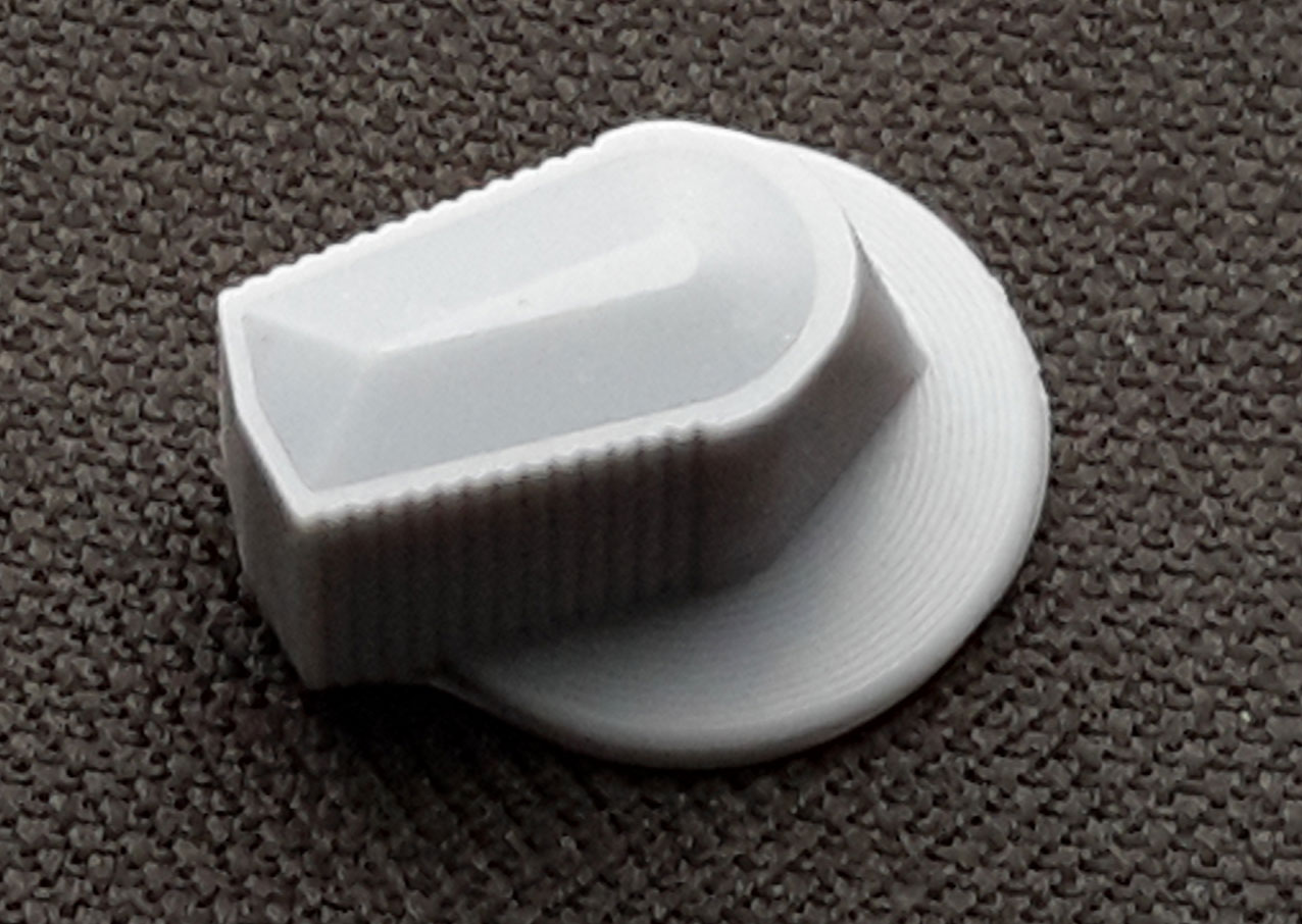
try this Les Canopy Defog knob 42mm.STL
-
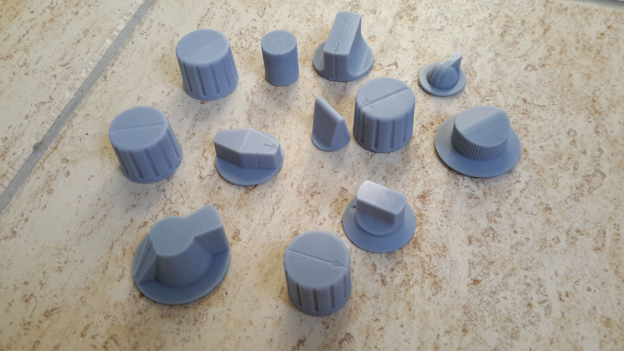
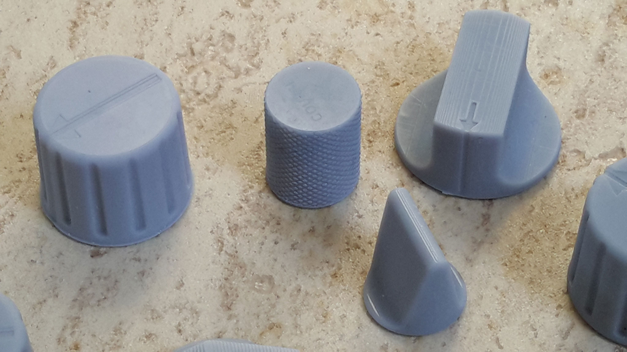
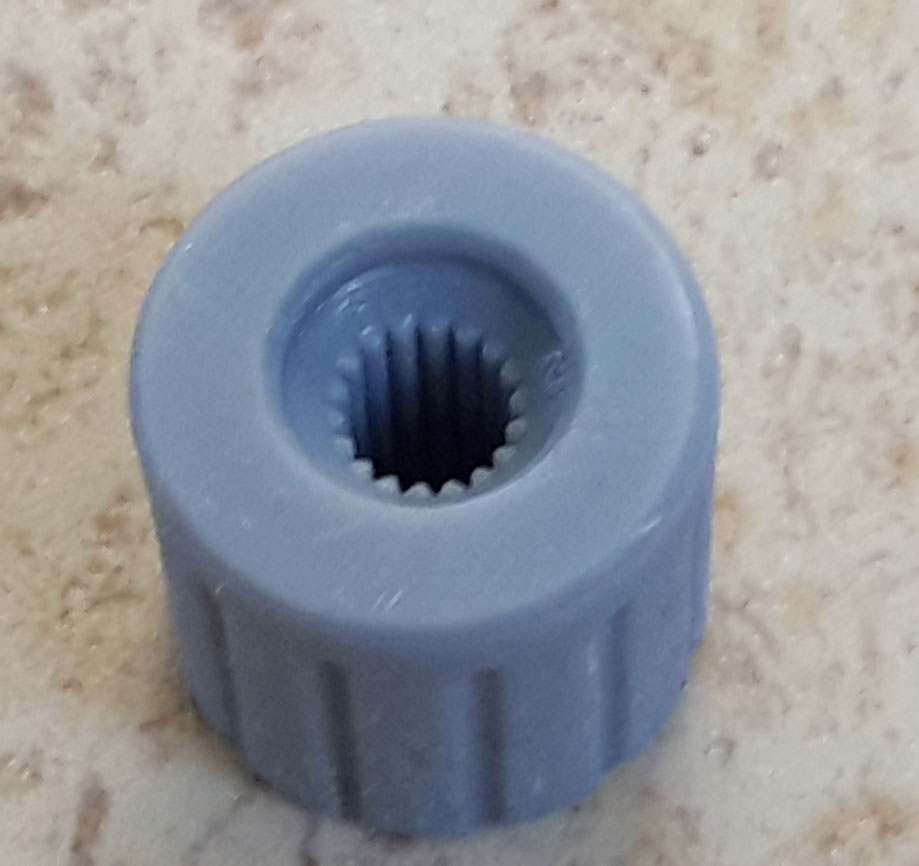
Sure - remembering that I have sized mine for my rig mine is smaller than the real one, but if you let me know the diameter of the disc part I can change my file to suit These are printed with a resin printer, in this case an AnyCubic Photon Mono X Les

-
Hi all, I've designed and made some 3D printed knobs to go with my A10 cockpit, they are sized to suit my panels and fit on 18 splined potentiometers, rotary encoders and switches. Happy to share the .sldprt or .stl files if anyone is interested Les
-
Switch panel programmable OLED labeling screens - DIY
lesthegrngo replied to lesthegrngo's topic in Home Cockpits
here are two similar ones, one 0.87", one 0.91" https://www.ebay.com/itm/293294163286?hash=item4449b1c556:g:-iEAAOSwndFdsQRC https://www.ebay.com/itm/363309596048?_trkparms=aid%3D1110006%26algo%3DHOMESPLICE.SIM%26ao%3D1%26asc%3D232195%26meid%3D6e5ea66ef6ce45c487f77b97bf69c21d%26pid%3D101195%26rk%3D2%26rkt%3D12%26mehot%3Dco%26sd%3D293294163286%26itm%3D363309596048%26pmt%3D1%26noa%3D0%26pg%3D2047675%26algv%3DSimplAMLv9PairwiseUnbiasedWebWithSearchFilterPromotion%26brand%3DUnbranded&_trksid=p2047675.c101195.m1851 cheers Les -
Just adding a response as I am on the move again, so searching for anyone in the new location Les
-
Switch panel programmable OLED labeling screens - DIY
lesthegrngo replied to lesthegrngo's topic in Home Cockpits
All those labels could be replaced by OLED displays, there are 0.87" ones that are 128 x 32 pixels that would be fine for the text in the pictures above Les -
Thanks again - and yes, the scale thing caught me out on one model I was using just to play around with. Remember the Eagle Transporter from Space 1999? There is a downloadable model in sections on the web (Grabcad I think) and when I opened that, it was damned near full scale! At first I couldn't understand why it didn't seem to open, it's only when I selected entire part view that it 'appeared - it was like 5 metres across! I might need a bigger 3D printer..... Cheers Les
-
Hi Vinc. Yes, for simpler ones like knobs and so forth that was a good workaround. I did a couple last night to test (COVID era Saturday night anyone?) and the models were indistiguishable from the originals. I also found that not all .stl are the same - there were a number of different files, and some of them could actually be saved as .sldprt models in Solidworks, and while you are left with an unmodifiable solid in terms of the individual polygons, I could actually use the faces on it to generate sketches from which I could make new features. Most, but not all could have holes extruded through them, however some could only have features added, with no way to make cuts or holes in them. Nonetheless, certainly it was good knowledge, and my advice to anyone who wants to do the same is to try a couple of methods first before remaking the model Cheers Les
-
Guys, I like others have downloaded and been grateful to the guys out there that have produced the .stl files for various bits and peices for us to print. However I occasionally find that there is one that I need to modify, for example making it conpatible with a D shaft, or making the hole smaller, and sometimes having to reduce a dimension to make it fit. Unfortunately my version of Solidworks doesn't seem to want to play even when you convert it to a .sldprt model, they become a fixed component that resists modifiocation completely. If anyone has any idea how to do that sort of simple modification I would be grateful for their help. For info I tried Blender, after reseaching online, best to keep quiet about how that went...! Cheers Les
-
I use a combination of a chinese K40 laser cutter/ engraver and chinese 3040 router/engraver. Both bought from Amazon. Cheers Les
-
Experiments with stepper motor drivers for gauges
lesthegrngo replied to lesthegrngo's topic in Home Cockpits
Hi This is a development of Craig's stepper motor sketch that works, although you will have to play with the stepper config part to get the gauge moving in line with your own unit #define DCSBIOS_IRQ_SERIAL #include <AccelStepper.h> #include "DcsBios.h" struct StepperConfig { unsigned int maxSteps; unsigned int acceleration; unsigned int maxSpeed; }; class Vid29Stepper : public DcsBios::Int16Buffer { private: AccelStepper& stepper; StepperConfig& stepperConfig; unsigned int (*map_function)(unsigned int); unsigned char initState; public: Vid29Stepper(unsigned int address, AccelStepper& stepper, StepperConfig& stepperConfig, unsigned int (*map_function)(unsigned int)) : Int16Buffer(address), stepper(stepper), stepperConfig(stepperConfig), map_function(map_function), initState(0) { } virtual void loop() { if (initState == 0) { // not initialized yet stepper.setMaxSpeed(stepperConfig.maxSpeed); stepper.setAcceleration(stepperConfig.acceleration); stepper.moveTo(-((long)stepperConfig.maxSteps)); initState = 1; } if (initState == 1) { // zeroing stepper.run(); if (stepper.currentPosition() <= -((long)stepperConfig.maxSteps)) { stepper.setCurrentPosition(0); initState = 2; stepper.moveTo(stepperConfig.maxSteps/2); } } if (initState == 2) { // running normally if (hasUpdatedData()) { unsigned int newPosition = map_function(getData()); newPosition = constrain(newPosition, 0, stepperConfig.maxSteps); stepper.moveTo(newPosition); } stepper.run(); } } }; /* modify below this line */ /* define stepper parameters multiple Vid29Stepper instances can share the same StepperConfig object */ struct StepperConfig stepperConfig = { 500, // maxSteps 1000, // maxSpeed 1000 // acceleration }; // note cs im testing with 11 going to step (middle on easy drier) and 10 doing to direction (right on easy driver) // cs so in the code going on the basis that the first named number is step and the second is direction // define AccelStepper instance AccelStepper stepper(AccelStepper::DRIVER, 11, 10); // define Vid29Stepper class that uses the AccelStepper instance defined in the line above // +-- arbitrary name // | +-- Address of stepper data (from control reference) // | | +-- name of AccelStepper instance // v v v v-- StepperConfig struct instance Vid29Stepper fuelQtyLBuffer(0x10ca, stepper, stepperConfig, [](unsigned int newValue) -> unsigned int { /* this function needs to map newValue to the correct number of steps */ return map(newValue, 0, 65535, 0, stepperConfig.maxSteps); }); void setup() { DcsBios::setup(); } void loop() { DcsBios::loop(); } Have a go and see if it works as is Les -
Experiments with stepper motor drivers for gauges
lesthegrngo replied to lesthegrngo's topic in Home Cockpits
What bit are you stuck with? I have sketches for the fuel gauge using X27 gauges, I can't imagine it would be too different? Les -
Switch panel programmable OLED labeling screens - DIY
lesthegrngo replied to lesthegrngo's topic in Home Cockpits
Actually, no, I was thinkning in a different direction. You may want to look over at SimHub, they have similar things to what you are proposing over there, for different games of course. The good thing is when youy use teh adruino setup they have, you can export the sketch to the arduino IDE and see how it all goes together, which would help you with this Les