lesthegrngo
-
Posts
1245 -
Joined
-
Last visited
Content Type
Profiles
Forums
Events
Everything posted by lesthegrngo
-
Switch panel programmable OLED labeling screens - DIY
lesthegrngo replied to lesthegrngo's topic in Home Cockpits
Yes, I think you can. Let me put together some ideas, the OLED modules can be mounted with a load spreader and on a 'hinge' that allows you to tale the load paths away from the screen. It would not end up with a very low profile panel, I can't imagine that you would get away with less than 20mm thick. The other point would be a very limited switch movement, 0.6mm or less. Smaller OLEDs may actually help. I'll sketch some stuff and post it, although if you have something that reads solidworks files that will help Les -
Switch panel programmable OLED labeling screens - DIY
lesthegrngo replied to lesthegrngo's topic in Home Cockpits
The displays are just that; simple OLED monochrome modules (search for 0.96" OLED on fleabay, loads turn up). However by careful design you can actually use the OLED's to push on SMD switches, but it would be for light work only and I couldn't comment on longevity. The PCB is indeed a DIY special, designed on Qcad and engraved on one of those 3040 chinese routers. There are TFT based solutions that do the same as this, the advantage of this is that you can range the switches where you want rather than being tied to a panel Les -
Switch panel programmable OLED labeling screens - DIY
lesthegrngo replied to lesthegrngo's topic in Home Cockpits
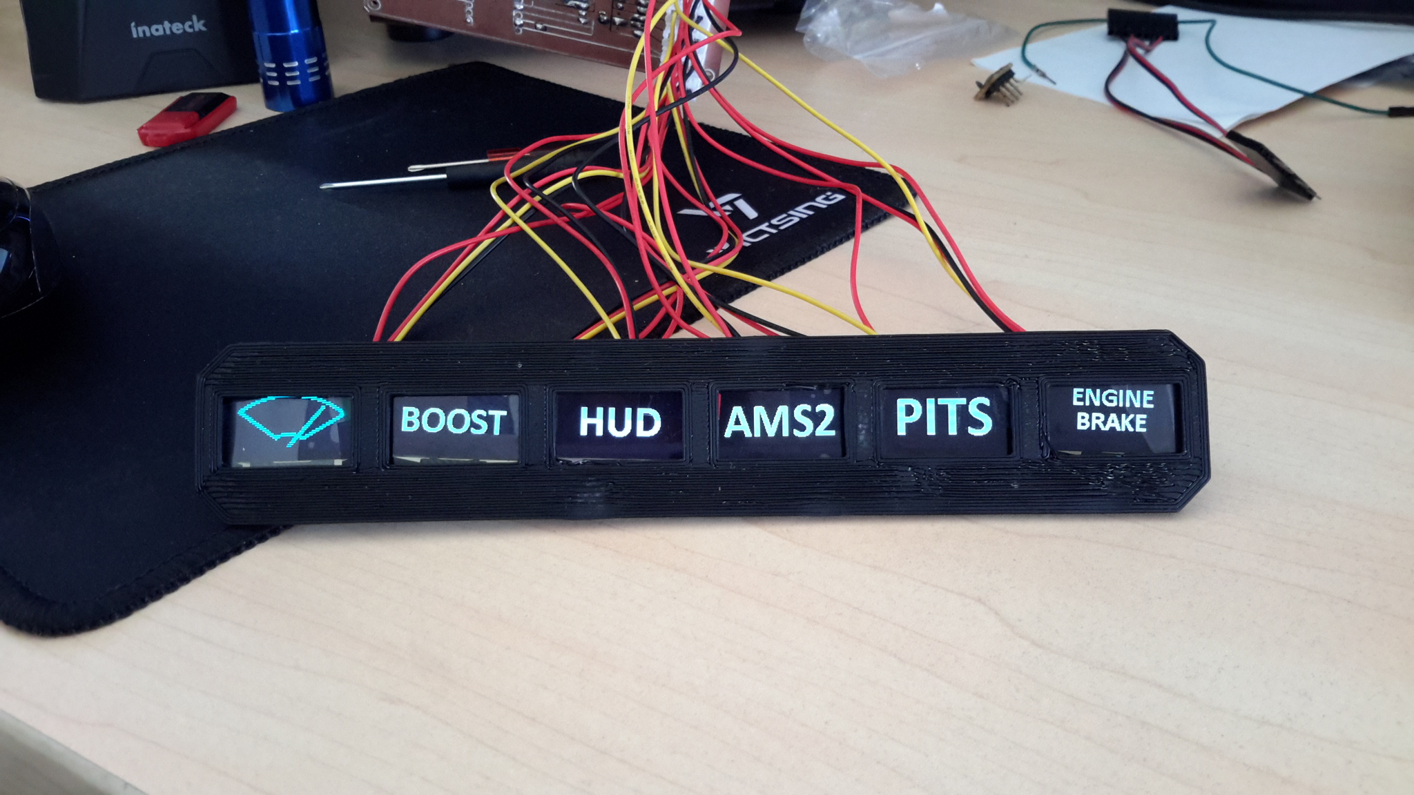
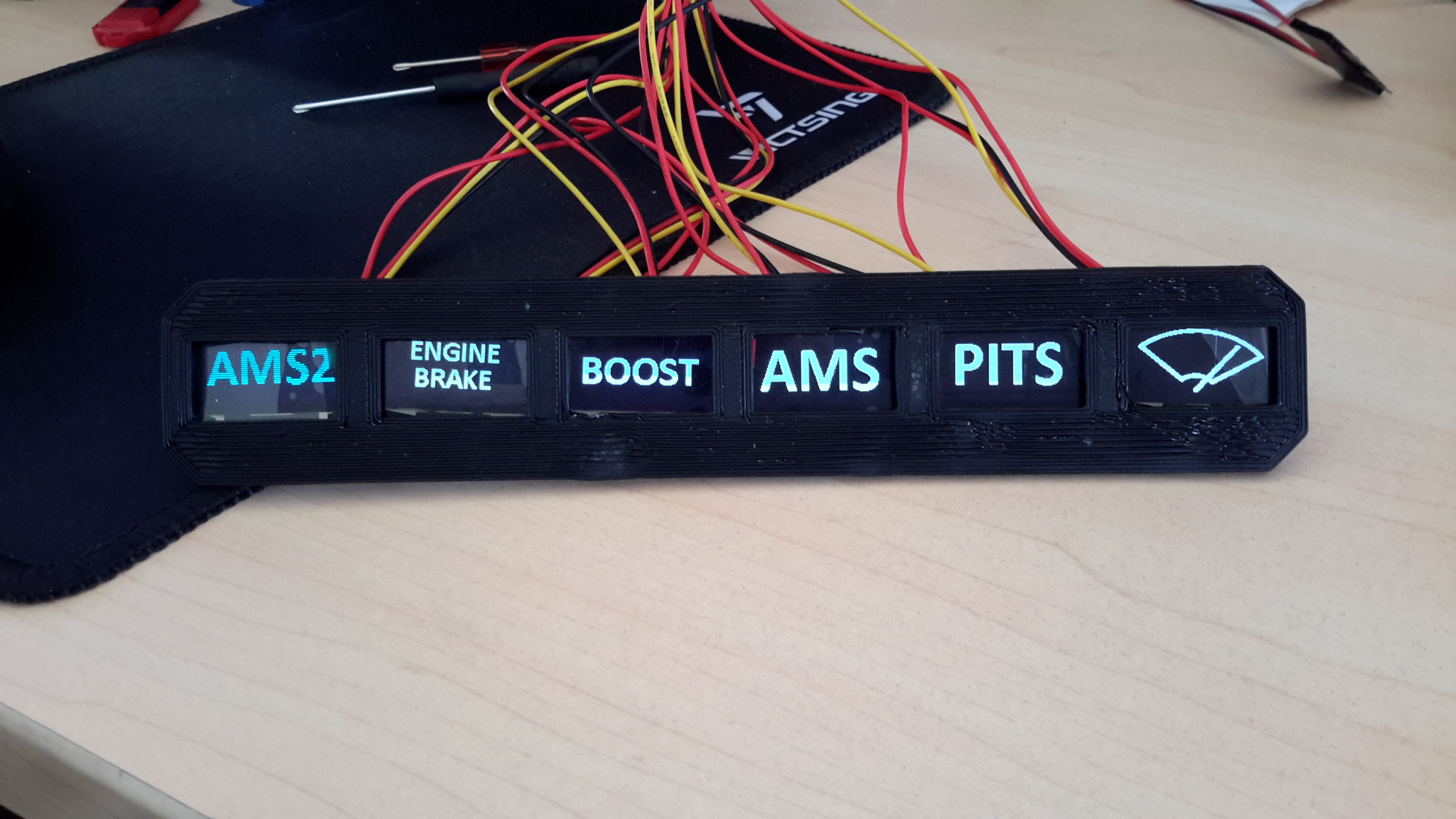
This is just to show the OLED's working. The actual OLEDs themselves can be placed anywhere you want, although I will make a custom panel for my race sim rig. I just did a fast and dirty 3D printed fascia to show the OLEDs in place (size constraints of 3D printer meant 6 max), bear in mind they are only loosely held. Basically, as you either move the rotary switch, or press the appropriate application button, the individual OLED images change depending on the positon of the rotary switch, and you can allocate one OLED to display the app selected (like AMS2 or AMS above) Each one of those labels is a little bitmap, really easy to make, and you can use any design or text that fits into a 128 x 64 pixel monochrome bitmap
-
Switch panel programmable OLED labeling screens - DIY
lesthegrngo replied to lesthegrngo's topic in Home Cockpits
An update on this - you can use pushbuttons in place of the rotary switch to select the game or map with no change to the sketch Les -
Switch panel programmable OLED labeling screens - DIY
lesthegrngo replied to lesthegrngo's topic in Home Cockpits
Thanks Matt As this was primarily for use with other sims other than flight, the need to integrate it with DCS Bios wan't there, but of course there is nothing stopping us making a modified version with more bells and whistles to suit us. However for a fast and simple standalone solution for showing what a particular switch / encoder / button does in game for multiple games (or other programs that have inputs) it has the benefit of being simple and relatively cheap. Les -
All, this is a bit of a departure from my A10 related stuff and pertains to the fact that my rig, ultimately, is a multi purpose one. One of the problems that I had was that I made a number of generic switch panels, which had fixed labels. This meant that if I assigned a control in one game, but used the same button for another control in another game, the labeling was wrong for one of them. As a result I have designed and actually built a panel based on OLEDs that you can use when making custom button / encoder panels for universal use. Essentially, you can make (at the moment) a panel with 7 switches which would connect to either an Arduino or button box of your choice, and then mount a 128 x 64 OLED above the switch. They connect to an Arduino and this displays a unique bitmap icon or text on each OLED, which can be different for each OLED. Using a rotary switch you can then select which game you want (and another OLED shows the game you select), and each individual OLED will then change to reflect the icon or text that represents the switch use in game. At the moment it is limited to 7 switch input displays plus the slected game display (total 8 OLEDs due to the use of an i2C multiplexer, but apparently it would not be hard to expand that to more using additional multiplexers. I have mine running with a four position switch for my race sims, and so can switch through Assetto Corsa, Assetto Corsa Competizione, Automobilista and Automobilista 2. By exporting a 128 x 64 black and white bitmap made in MS Paint to a .c file (plenty of free online versions) then copying that into a custom .h file I have icons representing windscreen wipers, indicators, ABS, brake balance, anti-roll bars, traction control...... the list is limitless, although practically you do have to ensure the .h file doesn't get too big. However I think you could safely do 30 bmp's in the .h file, which should cover most things not dealt with elsewhere. The way I have it uses the switch rather than encoder that's just how I initially envisaged it; it probably could be modified to use push switches or encoders It is not high tech, the bill of material is the following 8 x 128 x 64 i2C OLED modules (ones compatible with the Adafruit1306 library, not Ug2) 1 x TCA9548A multiplexer 1 x rotary switch with minimum 2 positions 1 x 328 Nano ( the 168 ones have too little memory) connectors and wires (I made a PCB with XH connectors) The circuitry is pretty basic, I don't think it would be difficult for anyone with even a rudimentary knowledge of electrics and electronics to do. If you have used Arduinos before, you won't struggle, The code is ready and working, albeit could probably do with tidying up, but I will try and edit it over the coming weeks to make it as easy as possible to modify with your own details, plus try and knock up some better instructions. **edit** forgot to mention, this is completely freestanding, and once done just runs off a USB charger. No need for DCS Bios or any other program Cheers Les
-
All, after months and months of not being able to get even one RS485 device working, despite it working before then suddenly stopping, I have finally been able to make it work again. It was not my wiring, circuits, chips or in fact any of the hardware at all that was causing the problem. Vlad333 on another post indicated recently that his stuff stopped working too, and that updating the Arduino IDE programmer (which forms part of the Arduino IDE program suit) resolved his problems. Today, using the same hardware that had refused to work, I simply updated the Arduino IDE, reflashed the Arduino Mega master and Nano slave, and it just worked first time. No hassles, no issues, it just works. Finally! I had in my previous posts questioned whether it was a software issue, as no matter how hard I tried I could not see any fault in my hardware. I was wondering if the PC I was using for gaming was at fault, well it seems my suspicions where in the right area. So for anyone like me that has found RS485 to be an enigma wrapped in an enema (sic), before you do anything else, make sure you have the latest version of the Arduino IDE, it can save you a lot of pain Les
-
Vlad333, you have finally unlocked the mystery of why I could not get RS485 working! I got round to trying it today, by upgrading the Arduino IDE program suite, then set up one of the RS485 enabled stepper boards just the same way as I had what feels like a million times before. It worked first time, fuss free. Thank you for that lead, you have unstuck something that had literally been non functioning for a year. Cheers Les
-
Hi there, can anyone advise if there is any way to increase the rate of transmission of data, or at least measure and log it for the purposes of outputting information to arduinos for use with stepper motors? As described in another thread, I have narrowed down some very poor quality of stepper motor movement for gauges to either the data rate refresh from the DCS BIOS output, or how frequently the Arduinos are processing that data to send to the stepper motor. Cheers Les
-
Experiments with stepper motor drivers for gauges
lesthegrngo replied to lesthegrngo's topic in Home Cockpits
Following on from this, I did a test yesterday using four X27-0168 steppers, each driven by an Arduino Nano via (respectively) an EasyDriver board, an A4988 driver board, the AX1201728SG driver and finally directly driven by the Nano. All were set with the DCS BIOS sketch for the APU temperature so that I could see how they performed with the different drivers at the same time. The result showed them all acting almost exactly alike, crucially including the jitters. At low pointer speed, they all virtually simultaneously stepped from one position to another, stopped together then stepped again. The steps were large relative to what the stepper motors are capable of. As a result, I am now sure that the pointer movement quality is driven by the output from DCS BIOS rather than the interaction between the stepper motor and driver or Arduino and driver. Even the addition of a smoothing algorithm made no difference at the lower speed due to the slow position refresh rate. So I have come to the conclusion that in order to improve the quality of the movement, my focus has to be now directed towards what is actually being transmitted by DCS BIOS, and at what rate. If the requested rate of change is not sufficiently fast, then as the stepper is capable of moving faster than the rate of position change, then it will move to the new position, stop and wait for the next change. If there is anyone in the community that is reading this that can comment of how to increase the data transmission rate, or position refresh rate I would like to know about it. I have looked through all the sketches I have used and cannot find any references to timing delays or such like in the ones for gauges, although I have seen them in ones for OLEDs. I remember seeing some expressions like Serial.begin(250000); being included in the void setup section, which I assume is something to do with the communication speed, however trying to splice into the current code just results in an error. So, the big question is what can be done to increase the data refresh rate for the gauge movement? Les -
Well, I will give it a go - I have lost many fruitless hours to RS485 in the past, so a couple more won't hurt! Thanks for the lead on this, fingers crossed! Les
-
I did a test today, using four X27-0168 steppers, each driven by an Arduino Nano via (respectively) an EasyDriver board, an A4988 driver board, the AX1201728SG driver and finally directly driven by the Nano. All were set with the DCS BIOS sketch for the APU temperature so that I could see how they performed with the different drivers at the same time. The result showed them all acting almost exactly alike, crucially including the jitters. At low pointer speed, they all virtually simultaneously stepped from one position to another, stopped together then stepped again. The steps were large relative to what the stepper motors are capable of. As a result, I am now sure that the pointer movement quality is (as you say) driven by the output from DCS BIOS. Even the addition of a smoothing algorithm made no difference at the lower speed due to the slow position refresh rate. So I will have to change tack on all my work to improve it. Les
-
That's interesting - I had RS485 working at the beginning and then it stopped working one day, and defied all attempts to resurrect it. I assume that you just update the Adruino IDE program? Cheers Les
-
All, in pursuit of some improved behaviour of things like gauge movement, OLED displays etc, I have found myself wanting to actually see a logged record of what is being output by DCS bios and when. To take the output for a gauge as an example, what I would like to do is see what signal say for the APU temperature is and how often the signal is refreshed Is there any way to do so? Cheers Les
-
Hi Vlad, are you saying that updating the Arduino bootloader will help with the RS485 not working Cheers Les
-
Experiments with stepper motor drivers for gauges
lesthegrngo replied to lesthegrngo's topic in Home Cockpits
I have finally got the AX1201728SG chips working. A batch of five of them were bought from a German supplier, after the first couple of attempts using Ebay sourced items got nowhere. Once soldered to the SOP/SSOP to DIP Adapter boards I had previously bought, I was able to fire up the stepper with some test sketches. However once I put in the DCS bios sketch (a test one using MiddleFart's sketch as a basis) while it would work in the game, it did not change the quality of movement measurably by eye. Now, I know this is early stages yet, as I haven't tried to play around with the settings in the sketch, and I need to sit down and try to understand how I am going to dovetail in the advanced controls to allow that. However what doesn't help is that for some reason the diagnostic program BoboBear produced doesn't work with this at the moment, so I am unable to do any empiric back to back tests This is the test sketch #define DCSBIOS_IRQ_SERIAL #include "SwitecX12.h" #include "DcsBios.h" const int RESET = 10; const bool InitToMax = true; struct StepperConfig { unsigned int MaxSteps; unsigned int MinSteps; unsigned int StepPin; unsigned int DirPin; unsigned int MaxAdjustment; unsigned int MinAdjustment; }; struct StepperConfig LeftFuelFlowConfig = { 3780, //315 degrees * 3 steps * 4 microsteps; 0, 8, 9, 0, 10 }; class X27Stepper : public DcsBios::Int16Buffer { private: SwitecX12& stepper; StepperConfig& stepperConfig; unsigned int (*map_function)(unsigned int); unsigned char initState; public: X27Stepper(unsigned int address, SwitecX12& stepper, StepperConfig& stepperConfig, unsigned int (*map_function)(unsigned int)) : Int16Buffer(address), stepper(stepper), stepperConfig(stepperConfig), map_function(map_function), initState(0) { } virtual void loop() { if (initState == 0) { // not initialized yet digitalWrite(RESET, HIGH); stepper.zero(); initState = 1; } if (initState == 1) { // zeroing if (stepper.stopped) { if (InitToMax) stepper.setPosition(stepperConfig.MaxSteps - stepperConfig.MaxAdjustment); else stepper.setPosition(stepperConfig.MinSteps + stepperConfig.MinAdjustment); stepper.update(); initState = 2; } } if (initState == 2) { // running normally if (hasUpdatedData()) { unsigned int newPosition = map_function(getData()); newPosition = constrain(newPosition, stepperConfig.MinSteps, stepperConfig.MaxSteps); stepper.setPosition(newPosition); } stepper.update(); } } }; SwitecX12 LeftFuelFlowMotor(LeftFuelFlowConfig.MaxSteps, LeftFuelFlowConfig.StepPin, LeftFuelFlowConfig.DirPin); X27Stepper LeftFuelFlow(0x10ae, LeftFuelFlowMotor, LeftFuelFlowConfig, [](unsigned int newValue) -> unsigned int { return map(newValue, 0, 65535, LeftFuelFlowConfig.MinSteps + LeftFuelFlowConfig.MinAdjustment, LeftFuelFlowConfig.MaxSteps - LeftFuelFlowConfig.MaxAdjustment); }); void setup() { pinMode(RESET, OUTPUT); digitalWrite(RESET, HIGH); DcsBios::setup(); } void loop() { DcsBios::loop(); } If anyone wants to weigh in with suggestions for improvements to this, please feel free, as usual anything I find out or try will be reported here so that people can learn from my mistakes! Les -
I used the commercially available SOP/SSOP to DIP Adapter boards for this, which worked well with other SMD chips, but whether it's a combination of poor soldering techniques (I have no access to a reflow oven) or poor quality chips (I have no way of testing them prior to fitting to the boards) is not clear. I have some new chips coming from a seller in Germany, so will have another go with those when they arrive **** EDIT **** As it happens they must have arrived yesterday, they were in the post box this morning. I mounted one of the chips on the adapter board, and I'm pleased to say that it worked perfectly using the schematic and sketch here https://guy.carpenter.id.au/gaugette/2017/04/29/switecx25-quad-driver-tests/ So, all I can assume is that the previous chips I had bought were DOA (from two different sources) so will have to be wary of that going forward. All I have to do now is splice in the code for the AX1201728SG drivers into one of the gauge sketches and then repeat the tests I did to see if it makes any difference to the quality of the movement. I hope so, after all the trial and error! Cheers Les
-
Thanks - I presume that the drivers were soldered to a breakout board, which I have tried without success to do. However your feedback does encourage me to keep trying, as it sounds like it is a good potential solution. Any tips on getting them to work? I was pretty careful to attach them to (purchased) surface mount adapter boards, but must have done something wrong! Do you have pictures of the PCB so that I can see if it the same type I have tried? Cheers Les
-
I think we'd all be interested in seeing what the driver you use with the X27's is, as I know that I am not alone in seeing jittery movement with them Cheers Les
-
You are having the same dissatisfaction as I have with the pointer movement on home made gauges - take a look at this link https://forums.eagle.ru/forum/english/dcs-world-topics/input-and-output/home-cockpits/278624-experiments-with-stepper-motor-drivers-for-gauges?t=276220 for some messing around I did. I am still trying to get the AX1201728SG stepper driver board to work as anecdotally it makes the movement smoother, and once I have any feedback (positive or negative) I will be putting it on here. Can you clarify whether the steppers you are using are the X27-168 type? Cheers Les
-
Maybe for you! I can't get it working after 18 months of trying unfortunately Les
-
****Edited with updated info**** I'm issuing a call out to any cockpit builders in Dhao, Qatar, as I am trying to progress my cockpit build. I am moving from Hungary to Qatar in Summer As you can see from this thread https://forums.eagle.ru/forum/english/dcs-world-topics/input-and-output/home-cockpits/243796-modular-a-10c-gauge-controller-for-dcs-bios/page6 I'm not doing badly, but recent events have taken their toll on my mojo, along with some frustration at some of the electronic details. If there is anyone nearby who is either interested in helping or is building their own and want to share resources, please let me know. I have access to quite a bit of equipment and tooling, and am willing to help make parts for both parties on the basis of mutual help. I am good at the mechanical side of it, but struggle with some of the more in depth electronics parts (for example RS485!). I've got a good inventory of parts including LED displays, OLED displays, electronic components including arduino nanos and stepper drivers, a CNC router, 3D printer, lathe, mill, all of which I am willing to share to get this moving. Hopefully there is a like minded person out there who is interested! Cheers Les
-
This is in theory a 12 position switch, but in practice it is a 4 way 3 position switch. However it can be modified by connecting all four inner contacts together OUTSIDE of the casing, then opening up the switch and cutting off 3 of the four sprung contacts. When you open the switch up, be careful not to lose the two tiny ball bearings or the spring that works them, otherwise your switch will no longer have the detents to hold the positions. The best thing is to try not to let the rotary part with the contacts and the top (black) housing come apart, but if they do look for the positioning cut out that helps you get the balls and spring back in the right place. It is not difficult, but it is fiddly, and I have done it on a load of mine successfully - though not without losing a ball or two in the process. Les
-
I thought that driving direct from a nano / mega / whatever arduino would help smoothness, but found it didn't make any difference, see this https://forums.eagle.ru/showthread.php?t=280127 Nonetheless, if you are not driving many motors it is a perfectly doable solution Cheers Les
-
Check out these two threads https://forums.eagle.ru/showthread.php?t=280127 https://forums.eagle.ru/showthread.php?t=276220 Les