tavarish palkovnik
-
Posts
476 -
Joined
-
Last visited
Content Type
Profiles
Forums
Events
Everything posted by tavarish palkovnik
-
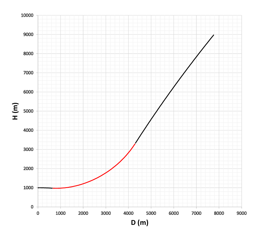
Hey @Katsu Nice to see you're using these numbers. You can even change data for your self...that's surprising to me. Then change active time, take off 3 seconds you gave extra using this average thrust value, although seems as just 3 seconds, that is extra 21 kilograms of non-existing propellant. This motor although seems as relatively simple is actually very tricky and it's quite difficult to make flight model which will be general for all cases. It's not difficult to the measure that it is impossible, everything is possible, however not in case how this program and model is organized, like you said it is simplified and it is understandable. Make it realistic would be such a hard work that anyone normal would gave up right in the start. Eventually one model but how many motors you have in game, that would be finished in next century. Tricky motor-tricky case...this launch which you called deck flight, take off non-existing 3 seconds, change thrust used for 10km altitude with average trust for 1km ( 15532 N ; Isp=223,4s) and you will get completely different picture probably nothing close to what you have in game now. So you saw HARM numbers as well, that one is different on it's way, there are others issues but at least this altitude issues are not so dramatic like in case of Phoenix. Phoenix is in that real pain and from all tactical motors I know, the worst for modelling because of it's widely open nozzle and nonlinear thrust. This deck flight, to show what all can happen, how many variables can appear ... One launch from level flight on 1km at 0,8M, and then after 2 seconds 6G overload for 10 seconds pushing missile upper in rear atmosphere. And with every second drag is in variable of course but thrust is also changing Just with lifting to this final altitude and because of lower ambiental pressure 7% of extra total impulse is achieved compared to what would be in level flight at 1km and missile goes over 1,9M while by using thrust from 1km missile barely reach 1,75M. Complicated motor indeed, not easy to work with, special in many points

-
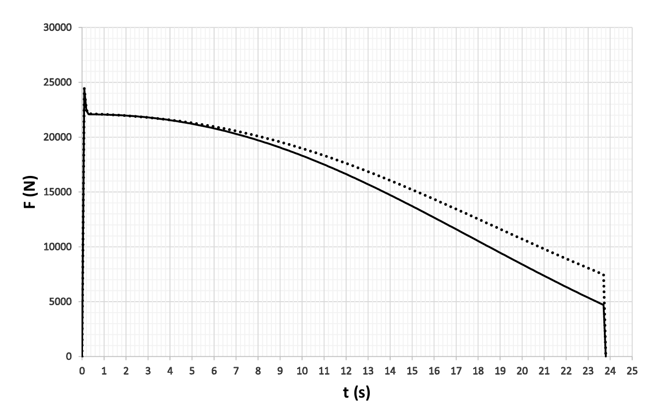
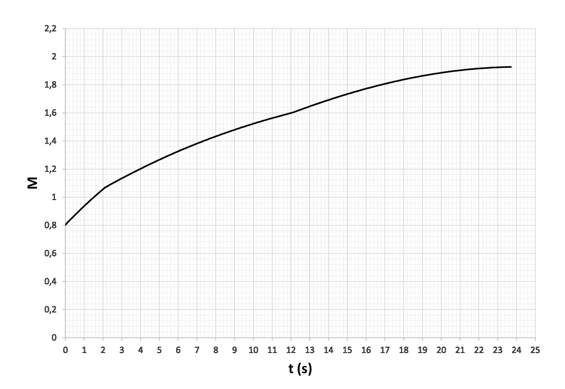
First thrust curves for sea level and 10km for reference, Itot=277,5 kNs and Itot=292,5 kNs This is of course weight of propellant with time, initial weight 127kg And Isp for sea level and 10km Your plan 53,3*3,2+8,4*13,5 seems as reasonable, although if we start from pressure rates I'm more for something about 125bar in boost and 25bar in sustain what for ''squared'' profile would be like 47,5*3,5+8,5*13 at sea level and 48,5*3,5+9,5*13 at 10km. Of course decision is yours, this is just thought of mine. Some guys will be disappointed when see values of Isp because it is HTPB and beside that it is American HTPB, but reality and wishes are different. This is non-aluminized propellant, relatively ''cold'' with some 3000K flame temperature, nozzle is as it is, and of course there is no rocket motor which will give theoretical maximum, simply some of total theoretical potential will be inevitable lost, and there are plenty of possible losses
-
''Red'' model is better to use as sample for consideration of shorter boost-longer sustain. Of course it is connected if propellant type inside is same and I think it is because only TP-H1159 is mentioned as type for HARM. By the way, there is also some doubt is this grain single or there are after all two grains inside. For casting I don't see reason for two grains of same propellant because it looks to me that single one can be done, but who knows. In some similar crosscuts where it is written boost grain and sustain grain (for example in Mk39 Mod.7 motor of Shrike, precursor of HARM) indeed two grains are inside and of two different propellants, Mk58 of AIM-7F also etc etc. I wouldn't be surprised with two grains. Anyway, I modelled it as single grain and for burning used 1,55*p˄0,36 and for all pressure rates. Unfortunately, for us trying to do this, luckily for constructors of motors, burning rates can be with additives modified to be different for different pressure. So 1,55*p˄0,36 is for range of 1000 psi (69 bar) but for 20 bar or 120 bar it can be different burning exponent and response. It's not easy of course to find answers with many open questions but I really think I'm close with these two options, red and blue. Simply with shorter boost, motor would go in pressure rates exceeding normal ones, and longer sustain is possible in this grain configuration only if reduce burning rate, and 20 bar pressure is for me some minimum for proper motor operation, lower than that motor could cough and die. On 20 bar it is only something about 4,55 mm/s of burning speed and that is minimum of minimum for reliable work of motor, or I believe that. If you can, of course I don't have objections, actually I would be glad, try to use these two with your dynamic model to see how it fits to it. Or just one, on principle truth is always somewhere in the middle Falcon's drag is from here -> ''Free-Flight Investigation of the Full-Scale Hughes Falcon Missile, D Configuration, to Determine Aileron Effectiveness and Damping in Roll'' Free-Flight Investigation of the Full-Scale Hughes Falcon Missile, D Configuration, to Determine Aileron Effectiveness and Damping in Roll - UNT Digital Library
-
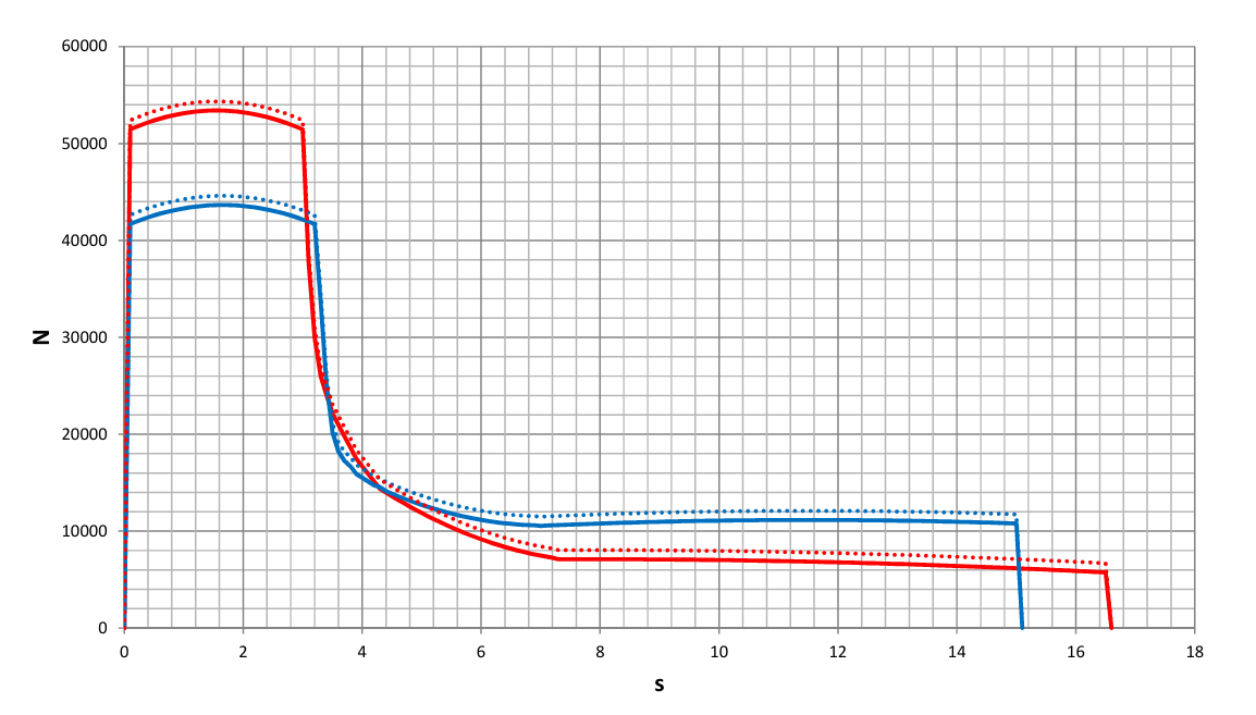
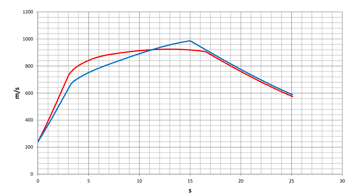
Few thoughts about HARM, there is nothing on the internet to be used as solid numbers, I mean how it's motor works in numbers. And I'm kind of stuck with it, seams as close but still final is missing, not sure what to select as final. There are only few crosscut graphics on the internet, and if those would be same then there will be no doubts but one is different then others, and that one is actually the most serious and the most relevant. Where to place second radial stress relief slot? That change everything in complete, would booster be stronger and sustain weaker and longer or weaker booster and shorter but stronger sustain. Obviously 3 graphics are showing that slot is in area of aft launch hook where motor is hardened and that has sense, usually such dividing in grain configuration is around such hardened place. But fourth one shows different, and although it is only sketch I can't not to take it seriously. After all, this one shows what is the most important in this work, grain configuration, half actually more then half is solved when having that. Propellant is known, just common non-aluminized HTPB based propellant, and there are few of such with given characteristics so together with grain configuration and also nozzle geometry which I have measured, it is almost everything on place to have something as output, how it works For sure, it is something of these two. Both are realistic, both are achievable, both are normal Pressure rates are in level of normal, a bit higher in this with stronger booster but still just regular. And this would be force output of these two options at 5km although with nozzle exit diameter of just 128mm there is no some significant gain with altitude It is nearly same total impulse about 285kNs so both should not be much different in dynamic, only distribution in time is different. I made few drop shots just to see where they are compared one to other, some launches from 2, 5 and 10km from horizontal and then gravity and atmosphere work, also some stupid non-realistic ballistic shot That's all close one to other, just slight motion adventage of stronger booster but insignificant. So I stuck, and don't know which one is the one. Almost forget to use sample shot what the Chinese gave ... Obviously they are about ''blue'' one but I'm not sure in that. I'm kind of more on side of ''red'' one...actually I don't know, it is 50:50. Both like said are realistic only I hate when don't have answer. Blue one is a bit more normal with pressures, it has slot where it would be expected to be, but the most relevant graphic shows different...70:30 for red. I would like to hear some thoughts, I know there are members here which knows this matter and which are curious as me. By the way, what you gave to HARM in DCS?
-
@henshao Thanks, highly appreciated Unfortunately null, still hidden like snake’s legs. But let’s go on with finding answers, it will appear somewhere sometime. Could be some awkward case when it is hidden so much
-
...
-
....
-
....
-
It would be better if you make one your own, you can start with simplified model and then step by step upgrade it with details like erosions and propellant initial temperature and involving more and more variables. When you make first one and learn basics it will be much easier to build around it. I don't have drag and lift coefficient data for Phoenix, I use estimated ones when making external ballistics with Phoenix, but that also can be calculated and to be quite precise
-
@Lans Missile launch weight is 1010,3 lb (458,5 kg) and burnout weight is 639,8 lb (290,5 kg) so it is 168kg of fuel more or less. There is some of difference most likely in igniter and ablative coating and gasgenerator but for calculation it can be taken as 168kg of fuel. Loaded motor itself is 465,2 lb (211 kg) so it 1,26 ratio and motor although it is steel construction due to relativelly low pressure and quality steel used for case is as light as it is. Case wall thickness is only 1,092 mm making total weight of case just 14,9 kg Yes, this motor is degressive, grain with two slots in shape as it is simply is with degressive burning surface. That's why they said average thrust is 5000 to 1000 lbf (22269-4454 N) and this most likely resulted with confusion and with sometimes calling this motor as dual-thrust motor what it isn't actually in full manner. This I made in just simple Excel with calculating integral of all these parameters which you can find in that paper, and just few of parameters are constant values (density of propellant for example or ambient pressure) and rest of it are variables for integral. Depending of integral step results are more precise. Just loop of numbers, burning surface+burning rate value -> chamber pressure -> thrust -> new burning surface and new burning rate value gives new chamber pressure and new thrust and in the circle until all fuel burned out If you like this and having interest in this amusing wasting of free time I'm willing to share some time of mine
-
@Lans Is it used in DCS I don't know, I've offered them this model but did they accept it I don't know. Most probably they didn't because it would crash down established ''theory'' that Mk47 and Mk60 give different output what is totally unreal and unfeasible for normal operation of missile with exchangeable motors. And unfortunately this ''theory'' spread out all over the internet like a flood. This is just my reconstruction of this motor based on long time digging and searching for valid information and finally it's ended with this, and I'm very sure this is it. Just some of literature that help a lot: ''Handbook Naval Air Launched Guided Missiles'' which gives general info about dimensions and masses ''Solid Rocket Motor Nozzles by NASA'' which gave a lot, what motor gives as thrust, how long it works, what is max pressure, very important it gave complete nozzle geometry and characteristics of throat insert, type of propellant etc etc and at the end paperwork ''Burn rate consideration in solid rocket motor performance prediction'' like cream on cake which finally gave how propellant grain in Mk47 is actually configurated and some for calculation important extra data. And when merge all that with basic stuffs about rocket motor propulsion you got this. Geometry of Mk47 Mod.0 gives exactly what is described for Mk60 Mod.0 and for me there is no doubt whatsoever it was like that in real...no matter what internet says
-
Grid fins are actually magnificent, those surfaces have some disadvantages in some segments but also huge advantages in others. The ones taking only one side of medal, don’t know anything about ballistic theorems and just blowing bubbles. Here on this forum, as well as in some others, so many talks about drag, and about everything else contributing flight paths, just random guessing Sorry but I got such feeling by reading these threads about rockets, motors etc
-
@tripod3 Good luck in finding answers how Oka actually flew. You will need it , I’ve tried to figure it out and than simply gave up. Both Elbrus and Oka had controllable motors, controllable in means of switching it off depending of targeting distance but while Elbrus actually flew in ballistic trajectory this Oka monster did not. And…internet is full of contradictions when describing Oka’s characteristics, maybe the most of all rockets
-
...
-
I’m looking for pressure-time diagram of Mk36 Mod.5 motor (Sidewinder 1C AIM-9D) or Mk50 Mod.0 (Chaparral). Or of any other Mk36 in 6-points star configuration, preferably with composite propellant. So if someone has it, it would be appreciated. There are few of such kind on dtic.mil when motor pulsing were performed in past, seams like similar but always something missing or simply is not what real Sidewinder motor should looks like
-
@draconus Look mate, I saw so many absurds here so that lot of things is coming on my mind, even this what you wrote last. After motor of R-27ER this one is of biggest interest of mine, and I put lot of work and time in finding answers. Perhaps they had some documents but it is question if they read it correctly. If you followed all what we wrote about it in sequences of finding answers how it works, you could see how sometimes numbers and all what is behind it can be tricky. One eventual case, what if they managed to find or get from somewhere pressure or thrust vs time curves for AIM-54 and one was for high and other for low temperature range, and somehow they took it as two different motors. Everything is possible, however slotted tube grain inside of Mk47 when processed gives exactly what is given to Mk60. I would really like to have comments of these chiefs which worked this out, comments regarding my results, that would be nice to hear and very much appreciated. Also even more I would appreciate if could get some words how Mk47 and Mk60 became different to them.