Vinc_Vega
-
Posts
641 -
Joined
-
Last visited
Content Type
Profiles
Forums
Events
Everything posted by Vinc_Vega
-
Well I didn't mean that resources but rather the stock you can pull from your shelves In good old Europe there is not really a market for such military aircraft parts. And if it was they are really expensive. That means everything has to be designed and produced by ourselves. Furtunatly there is this great help here in the forum Regards, Vinc
-
You're a lucky man to pull from such resources. Regards, Vinc
-
 Tha A-10 hasn't a separate parking brake. To release the brakes in the simulator (W key) you may push both pedals. To park the aircraft without chocks mostly the emergency brake is used. Regards, Vinc
 -
Assistance required converting a .bdf file to .c or .h
Vinc_Vega replied to lesthegrngo's topic in Home Cockpits
Hi Les, in described case I would propose to use two Nanos per panel. That should double the limit of useable inputs. Another method is to use port expanders. As you don't rotate all the switches at the same time. Regards, Vinc -
Assistance required converting a .bdf file to .c or .h
Vinc_Vega replied to lesthegrngo's topic in Home Cockpits
Btw. according to their readme the u8g2 should support the SSD1306 chipset. Maybe it's worth a try. Regards, Vinc -
Assistance required converting a .bdf file to .c or .h
Vinc_Vega replied to lesthegrngo's topic in Home Cockpits
Here you are Regards, Vinc Edit: following parameters have been used, if you need only specific characters please tell me bdfconv.exe -v -f 1 -m "32-255" ../bdf/DecimalVHS48.bdf -o DecimalVHS48.c -n u8g2_font_DecimalVHS48 -d ../bdf/DecimalVHS48.bdf type DecimalVHS48.c bdf.tga DecimalVHS48.c -
All multiplexed devices using TCA9548A stopped working
Vinc_Vega replied to lesthegrngo's topic in Home Cockpits
but too bad that nobody uses your setup and may contribute to your need. I personally use the Max7219 that uses a very different approach. Regards, Vinc -
All multiplexed devices using TCA9548A stopped working
Vinc_Vega replied to lesthegrngo's topic in Home Cockpits
Hi Les, try the linked example to see if your devices come up (TCA9548 I2CScanner.ino). Use USB connection to read out serial communication. https://learn.adafruit.com/adafruit-tca9548a-1-to-8-i2c-multiplexer-breakout/arduino-wiring-and-test#example-multiplexing-2115002 Regards, Vinc -
+ 1 Regards, Vinc
-
Understood, but the RS485 doesn't come up with a solution at the time. Regards, Vinc
-
Another option is to use one Nano and the Max7219 solution. It is fast and you don't need to care of shifting registers, the magic is to use the 48 LEDs as one ->LED-matrix<-. It won't bring stability over the RS485 network but will "block" only one USB port instead of two or three. Regards, Vinc
-
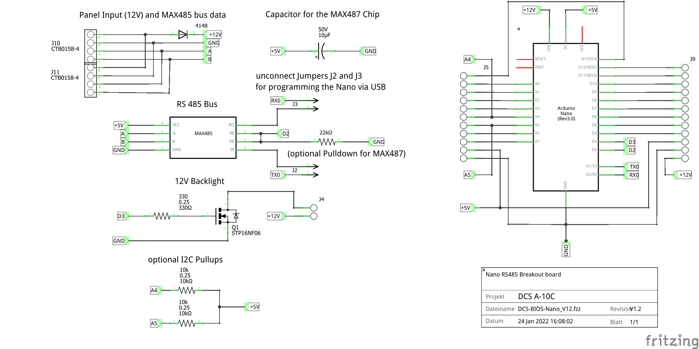
Hi Les, good point! Edit: found a notice at an older board layout, that the cap is optional for decoupling the MAX487. So I must have read that somewhere Regards, Vinc
-
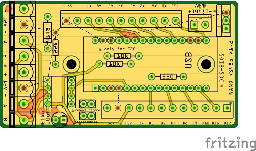
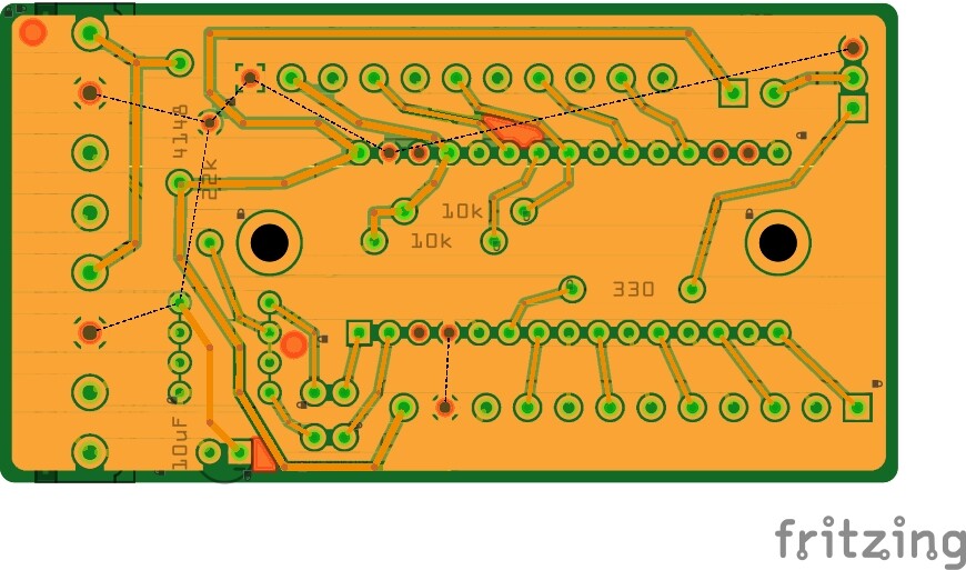
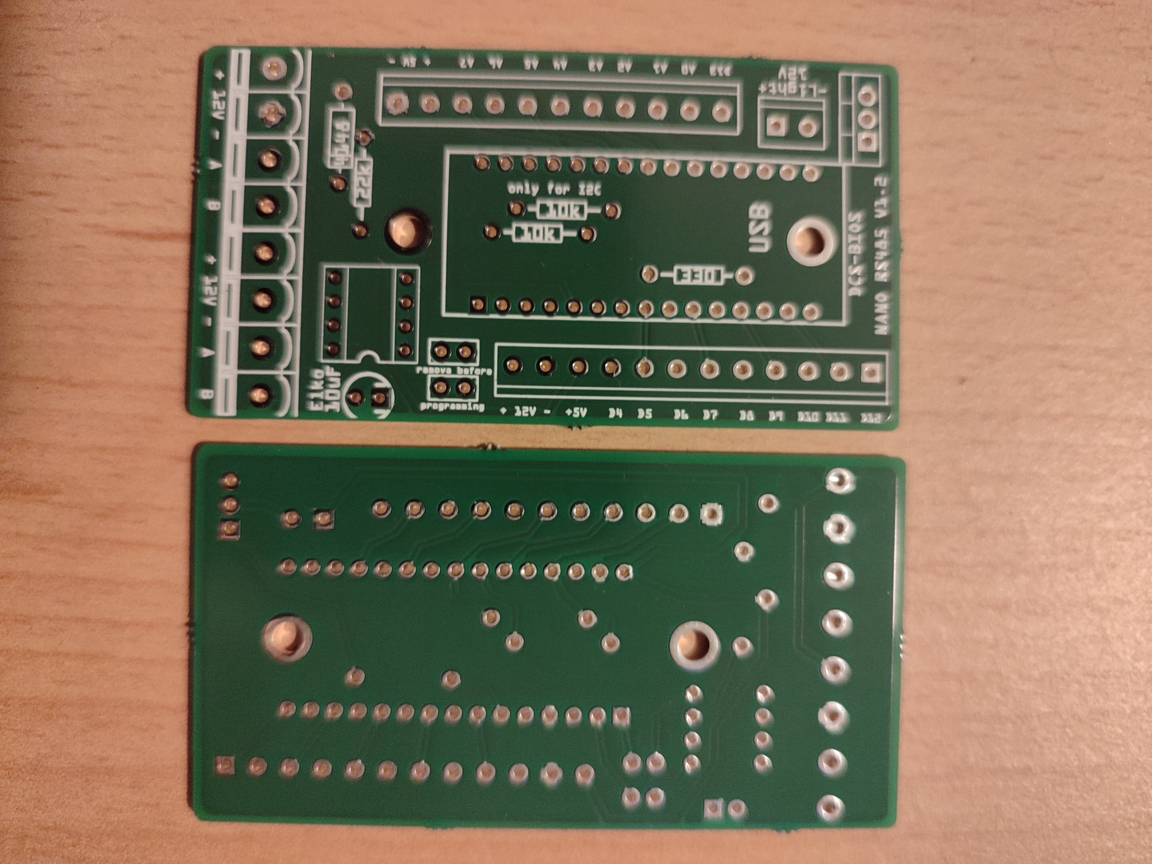
Here are some graphics of the fritzing design of my multi purpose Nano PCB. It is feeded by 12V from a PC power supply to the Nano's regulator by a 4-wire connector that also includes the A and B signals from the RS485 bus. A second connector of the same type enables the daisy chaining of further boards. I haven't tried to connect more than 3 boards so far. Further boards like the Max7219 driver chips may be connected to the regulated Nano's 5V output, motor drivers to the unregulated 12V output. Backlighting is (always) commanded by D3 (PWM capable for dimming) to a MOSFET and then connected to a separated 12V output. IC2 pullup resistors are optional to A4 and A5, jumpers are used to deconnect the RX/TX-Lines to programm a plugged Nano via USB. D2 is reserved for RS485 control with an optional pulldown resistor. D4 to D13 and A0 to A7 are not limited to use. Edit: 12V and 5V share the same GND planes top and bottom. Regards, Vinc

-
Have a look at the lower picture. The left most two connectors of the top PCB (it's always a top and down picture of the same board) are for power and RS485 input. Connector pins are bridged so multiple panels may be daisy chained. Edit: I may attach better graphics when I'm at my PC again. Regards, Vinc.
-
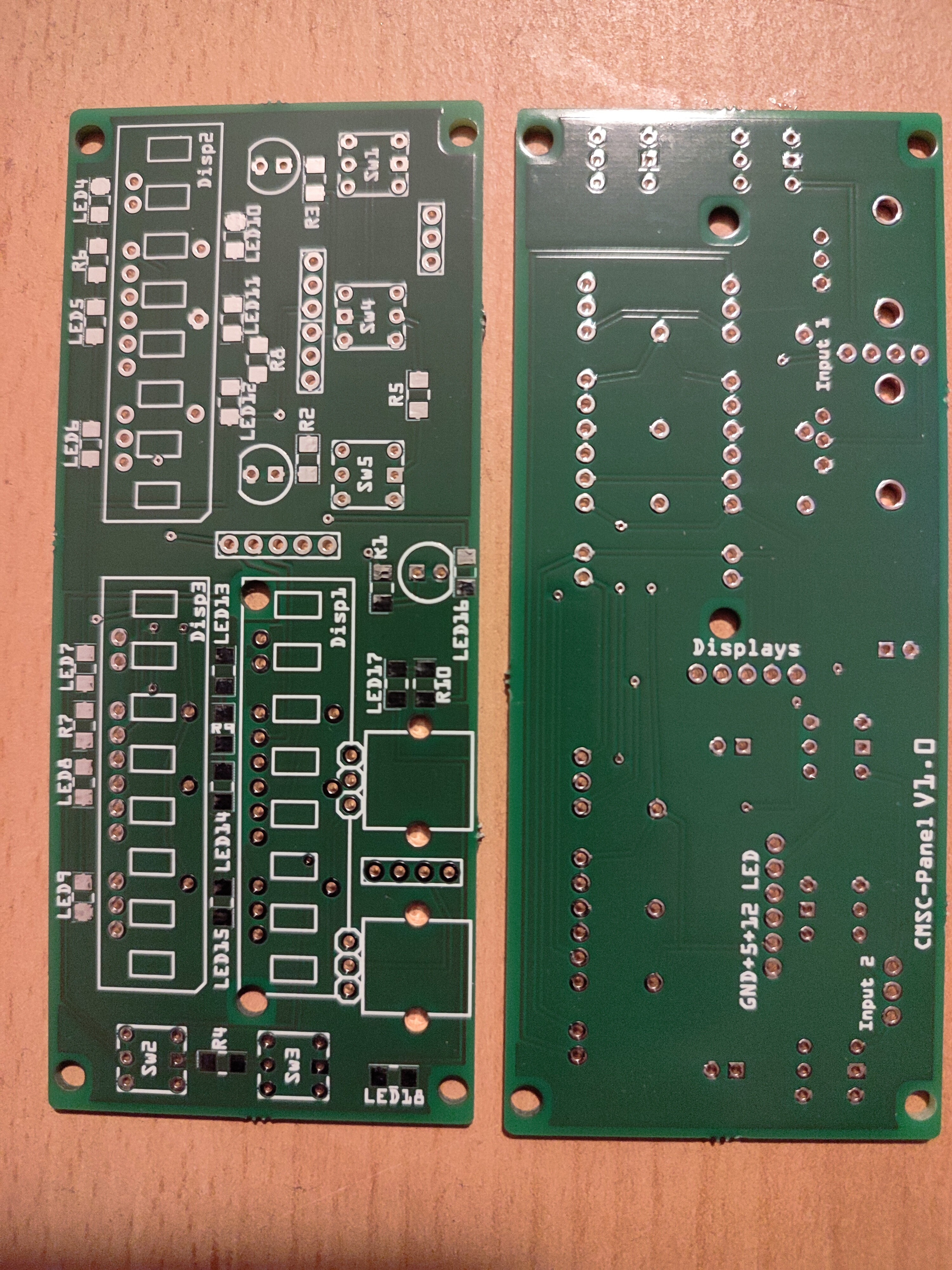
Hi Les, I use 12V to power almost all my panel PCBs for the backlighting. The Arduino is able to regulate it down to 5V than or o separate regulator may be used. 12V traces of the PCB are layed out little bigger than the other lines. But this is driven by the higher current consumption of the LEDs not the higher power supply. The LEDs are commanded by a MOSFET Edit: see pictures of the multi purpose Nano PCB and that of the CMSC panel. Regards, Vinc
-
Hi Deadman, are the US export regulations applicable to such equipment? If not, I was interested. Regards, Vinc
-
Just confirm that you are over 18. Unfortunately no pics of nude women Regards, Vinc
-
I didn't tried the RS485 option yet, but all key related programmings I did so far (not Dcs related) only with USB connected boards. I even don't think that the key bindings are part of the DcsBios RS485 protocol. Regards, Vinc
-
An 'important' question, opinions requested!
Vinc_Vega replied to lesthegrngo's topic in Home Cockpits
Hi Les, although the consoles in reality are painted grey (that's what I did so far), my wife would like them in black too Regards, Vinc -
Confirmed. I made a CDU screen with the ESP32 and it has almost the same "refresh rate" like with the Nano. So the limit must come from the bus speed. Regards, Vinc
-
It's not the right one. Take that file: https://github.com/dcs-bios/dcs-bios-arduino-library Edit: The difference is in the nowadays missing #ifdef Servo_h condition. Regards, Vinc Servos.h
-
Just use the servo.h from the DcsBios hub version. Regards, Vinc
-
You are right, the range of resistance is variable. But the 10 kOhm mostly is suggested in connection with an Arduino because of drawing lower current than using a 5 kOhm pot. What I wanted to underline in the above post is ensuring a linear pot and not a logarithmic one. Reading the failure description again I even suggest to test the hardware again. Just simply code the pot to another input and look if the behaviour still is strange or replace the pot and see if the nozzle controller works better. Regards, Vinc
-
Ensure that you use linear 10 kOhm potentiometers. Regards, Vinc
-
Looks like your rotary goes four steps per detent (from M to 4 to 8). Try to set the DcsBios command to one step per detent. Here are references, but I haven't tried it yet: https://github.com/DCSFlightpanels/dcs-bios-arduino-library/wiki/RotaryEncoder Regards, Vinc