Vinc_Vega
-
Posts
641 -
Joined
-
Last visited
Content Type
Profiles
Forums
Events
Everything posted by Vinc_Vega
-
Hi outbaxx, according to the structure definition I think you are right Regards, Vinc
-
Additionally it jumps from 1000 to 600 m. What values did you change within the code?
-
Hi Johan, I am not the author of the altimeter code and therefore have les ideas what it does. I only merged the lines for the needle with that of the km disk. It is possible, that the code for the km disk blocks the needle code, but I have no idea how to use the stepper class for a motor without IR sensor (that of the km disk). A way to verify blocking is to connect only one stepper to the arduino and going airborne. Use the same pin configuration for that test (e.g. 5,6,7,8). You therefore have to exclude the coding for the other stepper. If both stepper behaves good when standalone than you probably have to use several Nanos to drive the two motors. Furthermore it is a good idea first to get rid of all problems in the USB configuration. If all works fine you may go the RS458 way and have a look if the behavior is still good. If you want to reduce the turn angle of the km disk, you have to look into the map function int stepperPosition = map(newValue, 0, 65535, 0, 1260); 1260 steps are for a 315 degree angle (that is between both endstops) with 4 steps per degree (315 * 4 = 1260). If you want to turn only 270degrees you have to change the value accordingly (270 * 4 = 1080). This is half step mode (HALF4WIRE ) and probably may be changed into full step mode (3 steps per degree ??? depending on your stepper type) FULL4WIRE. You than have to find the correct number of steps for a turn of your motor. For the RS485 Master you have to use an Arduino MEGA and the RS485Master.ino sketch that is in your dcs-bios-arduino-library/Examples folder. Regards, Vinc
-
Hi Les, 536mm seems to be correct If that helps? taken from ->here<- Regards, Vinc
-

Thinking to quit, but it deserves one more (or more...) chanche on RS485
Vinc_Vega replied to Jocman's topic in Home Cockpits
Hi Jocman, your design looks good I didn't try to de-power the Max chip for onboard programming. As you can see, for that purpose I used two jumpers to de-connect the Rx/Tx lines from the Nano (J2/J3). Regards, Vinc -
Connections look good to me. Regards, Vinc
-
For the Mega please use the RS485Master.ino sketch from the dcs-bios-arduino-library example folder. Regards, Vinc
-
Thank you No1sonuk, so the issue can be explained. Johan, please change the hexadecimal values for both steppers like proposed above. adjusted code below Regards, Vinc
-
Thinking to quit, but it deserves one more (or more...) chanche on RS485
Vinc_Vega replied to Jocman's topic in Home Cockpits
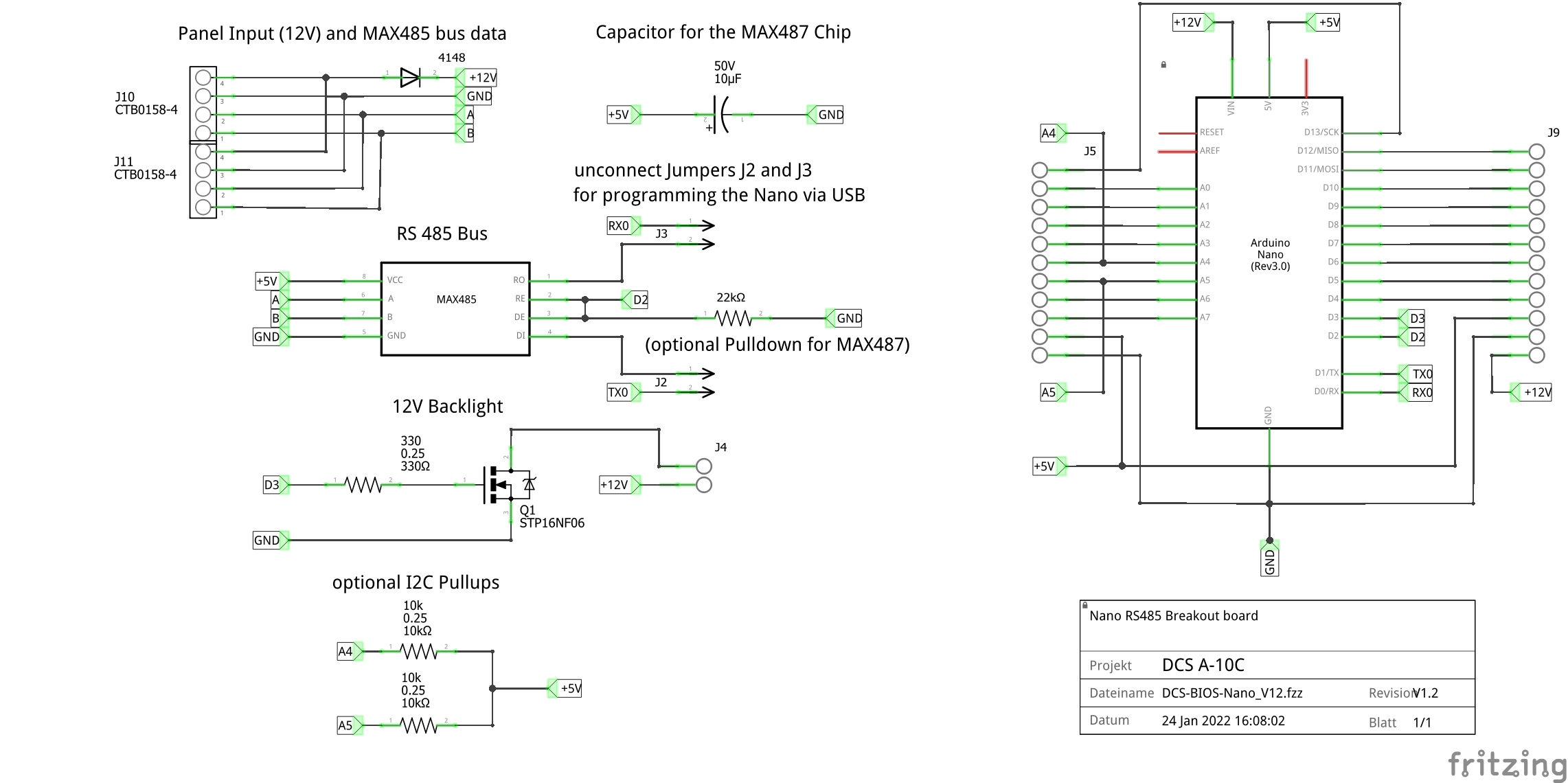
I'm currently using the 12V input and the stabilized 5V as output from the Nano. Have a look at the layout below for inspiration. 12V is also used to power panel backlight LED strips, dimmed by a MOSFET connected to pin D3 (PWM). The pullup resistors for the I2C bus at A4 and A5 are optional, same for the pulldown at the MAX487 chip. If you like the respective fritzing file of the breakout board, just PM me. Regards, Vinc
-
Can somebody please confirm the addresses for the altimeter of the BF-109? I have read out the Bf-109K-4.json file from the "AppData\Roaming\DCS-BIOS\control-reference-json" folder. But as I don't use the Flightpanels fork, the file may be outdated. Altimeter_FinePtr (1000m needle) 0x4248 (decimal 16.968) Altimeter_CoarsePtr (km disk) 0x424a (decimal 16.970) Altimeter_Pressure (pressure disk ) 0x424c (decimal 16.972) Johan, What happen to your gauge if you change the address of the 1000m needle and the km disk according to values read out of the Flightpanel's Bf-109K-4.jsonp file? try to change the hexadecimal addresses in line 165 DcsBios::IntegerBuffer altimeterCoarseptrBuffer(0x424a, 0xffff, 0, onAltimeterCoarseptrChange); into DcsBios::IntegerBuffer altimeterCoarseptrBuffer(0x424c, 0xffff, 0, onAltimeterCoarseptrChange); and that of line 149 Vid60Stepper AltimeterFineptr(0x4248, // address of stepper data into Vid60Stepper AltimeterFineptr(0x424a, // address of stepper data Regards, Vinc
-
Would you post your sketch pls? Regards, Vinc
-
Hi Johan, the lower movie shows the starting sequence. The 1000m needle moves slow and stops at zero. The km disk goes to the upper stop and back to zero. It's intended to do so. If you want to slow down the km disk at startup you have to lower the MaxSpeed within the Zero_Stepper0 routine at the end of the sketch let's say to 1000 and acceleration to 2000. Furthermore, I think that the direction of the 1000m needle has to be inverted. Change the pins to 9, 10, 13, 12 within the AccelStepper declaration. But what is shown in the upper movie? The km disk should not move when turning the encoder (or at least only from 0 to 1. Regards, Vinc
-
Thinking to quit, but it deserves one more (or more...) chanche on RS485
Vinc_Vega replied to Jocman's topic in Home Cockpits
First quick answer: do not power the boards by 12V and 5 V at the same time. The 5V will bridge the internal regulator but the pin can be used as stabilized output if using the 12V supply (e.g. for the MAX487 chips). Regards, Vinc -
PS: if you need more servos connected, just create more instances. Servo servo0, servo1, servo2; Regards, Vinc
-
My DCS-Bios multi-module solution and furthermore wireless 😉
Vinc_Vega replied to pavidovich's topic in Home Cockpits
Interesting stuff! But is it possible to use ESP32 boards as RS485 slaves? Regards, Vinc -
Okay, here we are with the ESP32 attached servo function for DcsBios. As my A-10C II has problems with the DcsBios connection at the time, I simply used the BF-109's altimeter needle to test the script. You need to install the ESP32Servo library and include it BEFORE all the DcsBio stuff. If your servo is not moving good, try to use a small delay between the steps. You therefore have to replace the line servo.write(map(newValue, 0, 65535, 0, 180)); with the respective function setServoPosition(map(newValue, 0, 65535, 0, 180)); Regards, Vinc
-
You may use the DcsBios library with USB connected ESP32 boards when using the Default_Serial option. There also is an ESP32 library available, dealing with the servo and PWM differences. Else you have to define all the values by yourself. I can bring in an example when I'm home tonight. Regards, Vinc
-
Consider to use the TM1637TinyDisplay6 library as that is for the big six digits displays. Have a look here: https://github.com/jasonacox/TM1637TinyDisplay#tm1637-6-digit-display---tm1637tinydisplay6 Regards, Vinc
-
Did you manage to bring the speedometer to 410 degrees and back? Regards, Vinc
-
Hi Johan, I merged Ian's code from that forum here (see page 1 for reference) for the 1000m pointer - including the zero detection - with that of the kilometer disk. As I don't have an IR sensor yet, I simply used a push button at pin 11 to simulate the signal. The 1000m pointer (AltimeterFineptr) is connected to pins 9, 10, 12 and 13, while the kilometer disk stepper (AltimeterCoarseptr) remains at pins 5 to 8. So the rotary encoder still has pins 3 and 4 available and pins 0 to 2 are reserved for the RS485 option. Maybe you have to tweak the values for maxSpeed and MaxAcceleration. You also may adjust the mapped values to the needs of your kilometer disk as 1260 steps are good for a 315 degree motion. But at least you should have a sketch to start from. Regards, Vinc
-
Hi Johan, I've found the issue! Don't know why, but I mixed up the adresses. After updating the plugins, the altimeter stepper worked fine with standard values. Sorry for that! I updated all the old postings with the corrected adresses. For the kilometer gauge you may use the following code, adress is 0x424a // Altimeter kilometer disk (0-13.000 m) void onAltimeterCoarseptrChange(unsigned int newValue) { stepper0.runToNewPosition(map(newValue, 0, 56535, 0, 1260)); } DcsBios::IntegerBuffer altimeterCoarseptrBuffer(0x424a, 0xffff, 0, onAltimeterCoarseptrChange); Would you tell me the kind of IR sensor you intend to use? Is there already an Arduino library or some code for that sensor available? Regards, Vinc
-
Yes, you need a lower stop and an end stop. If the stepper has 630 steps for a 315 degree turn you may go 820 steps for your 410 degrees spiral. (630 * 410 / 315 = 820) A reduction gear may also be used. Otherwise you need some zero detection like you planned for the second stepper of the altimeter. Regards, Vinc
-
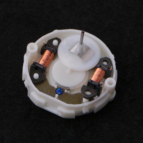
Hi Johan I reproduced the behavior of your stepper. It has been working good with the A-10C gauges but moves strange with the Bf-109. No idea what happens, but I'll do further investigation at the weekend. The Stepper direction may be chagend in different ways: 1) Quick and dirty by flipping the mapping interval. just change the last two values from int stepperPosition = map(newValue, 0, 65535, 0, 1260); to int stepperPosition = map(newValue, 0, 65535, 1260, 0); 2) Changing the pin order by software just change the pins pairwise from AccelStepper stepper0(AccelStepper::HALF4WIRE , 5, 6, 8, 7); to AccelStepper stepper0(AccelStepper::HALF4WIRE , 8, 7, 5, 6); 3) Changing the physical pin order As two pins are connected to each coil (see below picture) the pins may be flipped at the stepper or the Arduino connections. Just flip them coil wise like the pin order in the above AccelStepper object declaration. Regards, Vinc
-
I'll give you a tested answer when I'm home tonight. Regards, Vinc
-
Hi Johan, try another Nano, maybe there is something broken within the communication chipset. Regards, Vinc