Vinc_Vega
-
Posts
641 -
Joined
-
Last visited
Content Type
Profiles
Forums
Events
Everything posted by Vinc_Vega
-
Hi Les, do you mean the Oxygen Indicator Test Button? DcsBios::Switch2Pos envcpOxyTest("ENVCP_OXY_TEST", PIN); Regards, Vinc
-

How to Arduino micro pro power-supply for potentiometer
Vinc_Vega replied to Purzel's topic in Home Cockpits
Did you try to separate DCS and joystick related parts of your program? Comment all joystick related commands and try the DCS-Bios part first. Than you may see your potentiometer. Use a 10kOhm poti, and yes, that input doesn't need internal pullups. If that works for you, try to bring back the joystick part of the program. Regards, Vinc -
Thanks for the reply The Serial protocol seems to conflict the DcsBios communication. For debugging I mostly put Bios commands within compiler switches to separate them from Serial commands. See below for your imagination. Regards, Vinc // #define TEST // uncomment for testmode #ifndef TEST #define DCSBIOS_IRQ_SERIAL #include "DcsBios.h" #endif ... void setup() { #ifdef TEST Serial.begin(115200); Serial.println("Booting..."); #endif #ifndef TEST DcsBios::setup(); #endif ... void loop() { #ifdef TEST run_display_test(); #endif #ifndef TEST DcsBios::loop(); #endif ...
-
Yes, both "Serial" statements as they may disturb the communication managed by DCS-Bios. Regards, Vinc
-
Try to remove or comment the "Serial" statements within the Setup loop. Regards, Vinc
-
Raspberry Pi Pico $4 controller for USB interface
Vinc_Vega replied to Sprool's topic in Home Cockpits
Here you are: https://www.espressif.com/en/products/devkits/esp32-devkitc I successfully used -> 30 <- and -> 38 <- pin versions of the ESP32 dev modules with the Arduino IDE. Regards, Vinc -
Raspberry Pi Pico $4 controller for USB interface
Vinc_Vega replied to Sprool's topic in Home Cockpits
Well, the ESP32 should have almost twice the memory capacity of the Pico: Pico: 264kB RAM / 2 MB Flash ESP32: 520kB RAM / 4 MB Flash Regards, Vinc -
Raspberry Pi Pico $4 controller for USB interface
Vinc_Vega replied to Sprool's topic in Home Cockpits
The Pico works with the Arduino IDE. But if you want to have a fast chip set, why don't use an ESP32 dev board? Regards, Vinc -
Edited: Okay, so you want to run four displays by multiplexing the I2C bus. That's king size programming! Failure description says that you have two SETUP and two LOOP definitions. That's what I also see within your code. Furthermore, you include the "wire" library twice. Remove the last definitions for SETUP and LOOP, remove #include <Wire.h>, put the DcsBios::setup() and DcsBios::loop() statements into the top SETUP and LOOP and try to compile. But again: Have you tried out some simpler examples? Are the displays showing anything? Have you done the tutorial for the multiplexer board to learn how to talk to your hardware? -> https://learn.adafruit.com/adafruit-tca9548a-1-to-8-i2c-multiplexer-breakout/arduino-wiring-and-test Regards, Vinc
-
Have you got a "Hello World" sample running and see if your display is working with the setup? As you only have one display in your sketch, I would change the object Adafruit_SSD1306 oled(1); into Adafruit_SSD1306 oled; Regards, Vinc
-
https://forum.dcs.world/topic/134759-a-10c-warthog-switch-list/?do=findComment&comment=3208017
-
Hi Les, Within the 3Cameras.lua file is the following comment: note about fullscreen : directx doesn't allow fullscreen applications with resolutions more than primary display can handle, so multimonitor presets in DCS will fall back to windowed mode if fullscreen initialization failed ( this info also will be printed to dcs.log) Maybe you have to uncheck the fullscreen option for your setup? Regards, Vinc
-
new Monitor setup .lua file not visible in menu
Vinc_Vega replied to lesthegrngo's topic in Home Cockpits
Hi Les, put the .lua file into your user's Saved Games folder to see it in game. If there is no MonitorSetup folder, just create it. Saved Games\DCS.openbeta\Config\MonitorSetup\ Regards, Vinc -
RS485 network hardware questions / details
Vinc_Vega replied to lesthegrngo's topic in Home Cockpits
Theoretically, the capacitors should be as close as possible to the affected chipset. Practically, I would start to smooth out the voltage of the whole PCB by one capacitor only. If that doesn't work, each Nano may have it's own capacitor. Regards, Vinc -
RS485 network hardware questions / details
Vinc_Vega replied to lesthegrngo's topic in Home Cockpits
Hi Les, what power input do you use for the Nanos? Following has to be considered: If using the VIN power input pin, up to 12V can be applied to the board and internal regulation will be used to limit 5V to the chips and outputs. In case you supply less than 7V at VIN, the regulator may consume more than 2V. Than probably less than 5V will reach the chips and the board may be instabile. If using the 5V in pin, the Nano's power regulator is bridged and the full voltage goes into the chips and the output pins. But than the voltage supply has to be stabilized by the external capacitors. Regards, Vinc -
The u8g2 library needs a lot of memory. The total amount may depend on the used -> buffer size of the microcontroller RAM. The "F" within your U8G2_SH1122_256X64_F_4W_HW_SPI u8g2 constructor means "full framebuffer" and uses 2048 bytes for your -> display controller. You could try to reduce reserved memory when using the page buffer (1 = 256 bytes; 2 = 512 bytes). Have a look into the library's examples how page buffer has to be used / programmed. (I rarely used that) Regards, Vinc
-
As that was your configuration before going the 3 bus way, the behaviour is really strange! Regards, Vinc
-
Hi Les, according to the tutorial 8051 Interfacing and Demo Code following OLED pins are mandatory: 1 VSS Ground pin 2 SDIN D1 3 SCLK D0 4 DC 5 RES 6 CS 7 VDD1 (+3V) I'm not sure, if the other pin connections are optional. Beware of, that the NANO has also 5V for logical outputs. The U8g2 library indeed seems to support the SH1122 driver chip. Regards, Vinc
-
Try to connect the device via USB to the Arduino IDE, using a Nano as flash target. Pin connections of the rotaries and push button can be found in their Wiki. So it may be used with DCS Bios, but un-modified only as a single device. Regards, Vinc
-
I know the el-wires from a garden project. Total different technology than LEDs, so the wires cannot be dimmed. Their inverter may be powered by 12V or 2x AA batterys. It inverts the power to a high frequency (400 - 2000 Hz) and high voltage (60 - 120V AC). I think it depends on the colour. It's even cool for car projects Cheap inverters tend to create high frequency noise, quite but hearable. I think the same principle is applicable to the el-foils. A few things have to be considered during design. It could end in a try and error project by introducing additional high voltages and frequencies into your home made panels. So you may add electromagnetic problems to unshielded PCBs (acting like antennas) and microcontrollers. Regards, Vinc
-
There should be a RS485Master.ino within the librarys' example folder to adjust your settings. Ofcourse the TX enable definition must harmonize with the above .h file. Maybe you found the first issue to avoid further problems Regards, Vinc
-
Yes, it is intented to do exactly this. But I haven't done so yet. Extract from the master sketch: /* If you have less than three transceivers connected, comment out the corresponding #define UARTn_TEXENABLE_PIN lines for receivers that are not present. */ #define UART1_TXENABLE_PIN 2 #define UART2_TXENABLE_PIN 3 #define UART3_TXENABLE_PIN 4 Regards, Vinc
-
Have you already tried to use the second and/ or third RS485 bus of the Mega? Naturally the master sketch has to enable that setup. So one bus line could go to each side console and the third bus may be used for the Main panel. Regards, Vinc
-
Environmental panel gauges not functioning
Vinc_Vega replied to lesthegrngo's topic in Home Cockpits
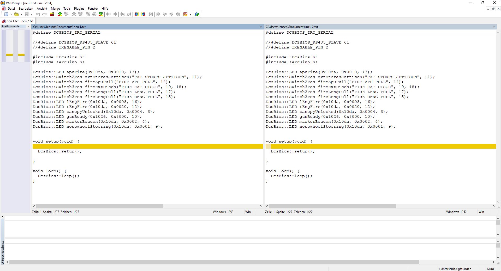
Hi Les, both files compile without error. Using ->WinMerge<- I've found the only difference is two SPACE characters in line 24, not visible to the naked eye within the second file. That's the blank line after "void setup". That makes no difference to the compilation. It must be an other problem in your setup. Regards, Vinc
-
see original posting for an answer