Vinc_Vega
-
Posts
641 -
Joined
-
Last visited
Content Type
Profiles
Forums
Events
Everything posted by Vinc_Vega
-
I have no idea on the used matrix nor the actionbuttonset class, but is it working if you put a "&" infront of the encoders' pin definitions? like &in_mat[5][1], &in_mat[5][2] Regards, Vinc
-
Hi Les, the TEST light for the TACAN not always shows up in the cockpit. You have to switch the panel in REC or T/R mode first. Than change the channel and push the test button. The LED only lights once, until you change the channel again or switch between REC and T/R. No idea if this is intentional behavior or a bug. For me the Switch2Pos option works fine (pin A1). Regards, Vinc
-
Hi Les, have you tried the Sparkfun solution for bricked boards? Regards, Vinc
-
 Hi Les, Connect the Mega's D0 (RX0) to RO of the RS485 board or Max487 chip, D1 (TX0) to DI and pin D2 to DE and RE. Than TXENABLE_PIN 2 within the slave sketch and that's it for a Mega. Regards, Vinc
 -
Help requested geting a sketch to run with RS485
Vinc_Vega replied to lesthegrngo's topic in Home Cockpits
Hi Les, why don't you use the lower hard stop of the stepper as zero point of your scale? Simply adjust it when puting in the pointer during assembly of the gauge. Than you let return the stepper within the sketch's SETUP routine to the absolute minimum (more steps than maxsteps backwards) and so have calibrated the scale. Regards, Vinc -
Reverse Engineering your own stuff?
-
Hi Les, as you already assumed, pins A4 and A5 are preset as I2C bus pins for the Nano and the Uno. Have a look at the pinout in my last posting. They are "hard wired" to the Data channel (A4) and Clock frequency (A5) and can't be changed for that boards. That is in analogy to No1sonuk' s statement regarding the communication pins D0 and D1. You may change the pinout or add I2C interfaces by software, have a look at the SoftWire library. But that should slow down the processing speed of the sketch. Have a further look at pins A6 and A7, they exclusively are connected to the Analogue Digital Converter and therefore can be used as physical inputs only (not as outputs). Maybe that's a reason why they are missing for the Uno layout. Regards, Vinc
-
Hi Bob, I use DCS-BIOS Version: v0.10.0+64, most files of the Library are from April 2019. The A-10C II modul should be from October 2020. Regards, Vinc
-
Hi Les, for LED output also D13 should work. If not connected via RS485, D0 to D2 may work as output too. -> Pinout <- Regards, Vinc
-
Sorry, can't help. I use the original DCS-Bios version (not the Flightpanel's) and don't get any compilation errors. Even not with an original and unmodified Switches.h file. What version of DCS-Bios and what kind of Arduino board do you use? Regards, Vinc
-
There is a separator missing between pins 32 and 33.
-
Yes Bob, you have to put your pin numbers within the curly brackets The line regarding the "invert logic" has to be observed. Just change if the wheels turn strange. Regards, Vinc
-
Hi Bob, As already stated, you don't have to connect all 4 switch pins to the arduino. If you push the respective thumb wheels in the cockpit you'll see, that they only can be turned from 0 to 7 (3 bit). The second Mode 1 wheel is turnable from 0 to 3 (2 bit). Therefore for the most wheels the code snippets could read as follows: const byte iffMode1Wheel1Pins[3] = {A14, 32, 34}; // tree bit (0 - 7) DcsBios::SwitchMultiPosBCD iffMode1Wheel1("IFF_MODE1_WHEEL1", iffMode1Wheel1Pins, 3); and for Mode1 Wheel2 you need to connect only 2 pins: const byte iffMode1Wheel2Pins[2] = {A15, 33}; // only two bit (0 - 3) DcsBios::SwitchMultiPosBCD iffMode1Wheel2("IFF_MODE1_WHEEL2", iffMode1Wheel2Pins, 2); Regards, Vinc
-
Hi Bob, did you put in the namespace declaration for the SwitchMultiPosBCD before calling the DCSBios:: statements? #define DCSBIOS_IRQ_SERIAL #include "DcsBios.h" namespace DcsBios { class SwitchMultiPosBCD : PollingInput { private: const char* msg_; const byte* pins_; char numberOfPins_; char lastState_; char readState() { unsigned char i; unsigned char state = 0; for (i=0; i<numberOfPins_; i++) { unsigned char j = numberOfPins_ - i - 1; // state |= (digitalRead(pins_[i]) << j); state |= ((digitalRead(pins_[i]) ^ 1) << j); // to invert logic } return state; } void pollInput() { char state = readState(); if (state != lastState_) { char buf[7]; utoa(state, buf, 10); if (tryToSendDcsBiosMessage(msg_, buf)) lastState_ = state; } } public: SwitchMultiPosBCD(const char* msg, const byte* pins, char numberOfPins) : lastState_(0) { msg_ = msg; pins_ = pins; numberOfPins_ = numberOfPins; unsigned char i; for (i=0; i<numberOfPins; i++) { pinMode(pins[i], INPUT_PULLUP); } lastState_ = readState(); } }; } const byte iffMode1Wheel1Pins[4] = {5, 6, 7, 8}; DcsBios::SwitchMultiPosBCD iffMode1Wheel1("IFF_MODE1_WHEEL1", iffMode1Wheel1Pins, 4); void setup() { DcsBios::setup(); } void loop() { DcsBios::loop(); }
-
You'r welcome Sir! If you want to know how the signals are combined to make decimals, have a look at PC Flight's description of the switches. Here "C" is the common ground (GND) and 1 to 8 are the switch pins. As you only need at max 3 bits for the IFF (you can dial only from 0 to 7), pins 1, 2 and 4 have to be connected to the arduino. Regards, Vinc
-
Yes, that class is not part of the Control Reference but is the right one for thumb wheel kind switches with BCD output. For the code and more explanation on that, please read the discussion linked above. Edit: FSFIan is the author of DCS-BIOS and intruduced the SwitchMultiPosBCD in that posting. Regards, Vinc
-
BCD means "binary coded decimal", so the object already converts signals from the connected pins to decimal outputs (0 to 10), or in the IFF case 0 to 7.
-
Hi Bob, Try the following snipped for the ZERO - B - A - (HOLD) switch const byte iffCodePins[4] = {PIN_0, PIN_1, PIN_2, PIN_3} DcsBios::SwitchMultiPos iffCode("IFF_CODE", iffCodePins, 9); For the wheels, see Les's above post. Regards, Vinc
-
Issue with Rotary Switches in F/A-18C Hornet Cockpit
Vinc_Vega replied to hrnet940's topic in Home Cockpits
I can't see the radar switch related video. But according your code the Radar_SW is connected to a rotary encoder and not to a rotary switch. Encoders act like increasing or decreasing a value as long as you turn it. Jumps between the steps mostly are caused by encoder bouncing. That means, there are voltage spikes in between two steps of the rotary encoder. Do a search for debouncing a decoder. That can be done by hardware or software filters. Regards, Vinc -
Hi Les, you are right, the Nano's PWM capabilities are limited to digital pins 3, 5, 6, 9, 10 and 11. As far as I remember, pins A6 and A7 can only be used as analogue (and digital) inputs, but they are still good for connecting switches to GND. If you are using the RS485 bus, you are loosing pins D0 to D2, if using the I2C bus you additionally loose pins A4 and A5. Using D13 as an input sometimes can cause problems, as the onboard LED is wired to it. I can't confirm your trouble with pin D3. Had never problems with it. To get more inputs / outputs, 8 or 16 bit port expanders could be used. Here is a good reference to the Nano pinout -> LINK <- Regards, Vinc
-
I think, that he wanted to know if Megas instead of Nanos/Unos could be used as slaves. I haven't tried that yet. Regards, Vinc
-
Yes John, that's the way, switch sync is still working within my panels Regards, Vinc
-
DCS-Bios + Arduino + MAX7219 = Caution Light Panel
Vinc_Vega replied to ClayM's topic in Home Cockpits
1. You have to use an 8 by 8 matrix. If you have a look into the code you can see, that the CLP is split into two halfs. In the case below it's 8 by 6 LEDs (top is 4 by 6 and below is another 4 by 6 matrix). So all 48LEDs can be used on one Max7219 chip. Original code is from here: https://gist.github.com/jboecker/1f37b5c0b44aec0d3f80 Below is my adaption for the CLP. 2. You only need one resistor for the 7219 chip to limit the current. Have a look into the data sheet or the LedControl documentation, it`s according to the forward voltage / current of your LEDs. 3. For a shematic look there: Regards, Vinc -
Stepper motor drivers for use with Arduino and DCS Bios
Vinc_Vega replied to lesthegrngo's topic in Home Cockpits
Years ago I found a strange behavior with the MiG-21's radar altimeter. The values were not linear scaleable. The problem could be solved by using the "multiMap" library for Arduino. Maybe that you are facing similar issues. Below is that part of my code: Regards, Vinc -
ExpressPCB advice sought for non rectangular boards
Vinc_Vega replied to lesthegrngo's topic in Home Cockpits
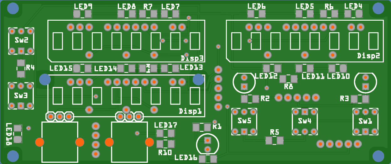
Solidworks is able to import step and stl files. Let me write more experience: I personally use Solidworks to model the panels and than export the PCB outline via dxf. That files can be imported to vector drawing programs to convert it into svg format, that can be used by fritzing. (The process is tricky and needs some practice. Unfortunately there are no sufficient tutorials on the internet.) Former I used Inkscape but now found a better handling with Adobe Illustrator. The svg images of the board can have any shape, including inner cutouts. I also had to learn how to create my own components in fritzing, what is a more complex thing. To place components I use temporary outlines from the dxf file that have to be deleted after populating the board. Most boards are produceable by Aisler, but I have not yet tryed their assembly services. Aisler's "Beautiful Boards Budget" has a minimum order of 3 boards. They also offer online PCB viewing opertunities, look below for my CSMC panel PCB. But Aisler accepts KiCad, Eagle, Target, Fusion and Sprint files too. Regards, Vinc