Vinc_Vega
-
Posts
641 -
Joined
-
Last visited
Content Type
Profiles
Forums
Events
Everything posted by Vinc_Vega
-
If touches can be programmed as a kind of dedicated arduino inputs, I could imagine that commands may be send to DCS-Bios. But I haven't done so yet. Regards, Vinc
-

Has anyone tried to do the A10-C digital clock with OLED panel?
Vinc_Vega replied to lesthegrngo's topic in Home Cockpits
Yes, I did. It has been tricky. I'll send a PM when home again. Regards, Vinc -
Thank you Tim, that seems to be a handy tool The other black box in the first picture is a power bank, am I right? (battery power for an USB port) Regards, Vinc
-
Hi Les,
for the engine's 10th gauge I want tu use a 0.42 OLED. There is a misprint on the PCP, it really has a resolution of 72x40.
Unfortunately the Adafruit_GFX library does not support that display at the time. Therefore I had to convert the sketch, using the u8g2 library. Fortunately that library is monochrome (black/white) and refrehes the display a bit faster.
If you want, I could send you the sketch.
Regards, Vinc
-
Let’s not limit this topic to code snippets but expand it to share some programming ideas or tutorials! Drawing analogue pointer needles on digital displays Sometimes it’s useful to show analogue gauges on digital displays, like it’s done in modern jet cockpits. In the following I want to describe some basics and the way I draw those tiny instruments. Considerations: To show a round gauge at your display, just let your microprocessor draw a circle and print some marks and values near it. Maybe that’s one of the following topics. But the most significant question for it is, which pixel defines the tip of the needle on your display. The answer is simple: You’ll tell it! As you already may know, your display is built like a Cartesian coordinate system, where pixels (dots) are addressed by simple x- and y-coordinates. Unlike printing a static pixel or some text in that rectangular coordinate system, the point below the needle’s tip is moving, unfortunately at a circle’s circumference. It easily can be described in polar coordinates. So the microprocessor really needs to know a little about higher-class math. At first let’s repeat the transformation of polar coordinates, please pull out your workbooks and pocket calculators! Just kidding To simplify this, that point exactly can be described by the distance from a reference point and the respective angle of the needle. Imagine the big hand of a clock that shows what time it is. If it’s 10 minutes past six, the longer hand is pointing at the two o’clock position. We could take the middle of the clock as reference point and measure the distances of the hand’s tip by using the hand’s length (or half of the clock’s scale diameter). The angle could be determined by counting the marks on the scale. But where do we start to count the marks? In math the starting point of that angle is defined at the positive x-axis (to the right), which means that we start at the three o’clock position of the scale, counting the marks upwards. The angle grows in the counterclockwise direction. Each mark for a minute at that clock’s scale is 6 degrees away from the next (360° / 60 minutes = 6) and the hand now points at 5 minutes to the zero mark (three o’clock position). That means, the point below the hand’s tip can be described as the needle’s length (that’s the radius of the scale minus the distance from the tip), in an angle of 30 degrees (6 degrees * 5 minutes). To draw that position on your display we have to transform that polar coordinate into the Cartesian system. Fortunately, we don’t have to do the math, that’s why microprocessors are for. We only have to use the right formulas within our Arduino sketches: The x-value can be found by multiplying the radius and the cosine of that angle, the y-value by multiplying the radius and the angle’s sine. Beware of, that the angle’s value has to be in radians (-pi to +pi) and not in degrees! But fortunately, our microprocessor is able to calculate that as well (2 * PI = 360 deg). One more interesting point is, that at our displays the positive y-coordinate points downwards, what mirrors all our former considerations. In the end that makes a growing angle rotating the needle clockwise at our display. Luckily that’s how most of analogue gauge work, like clocks, rpm-indicators or speedometers. Drawing the needle’s tip: When using digital displays such as OLEDs, you first have to initialise it within your code. It depends on the type of display and driver chips and should be content to other topics. Please use the examples, coming with the library of your display. To show the way here, I’ll be using a tiny 1.3 inch OLED with the SH1106 driver. Furthermore I’ll describe the procedures, using the “Adafruit_GFX” library. That’s just an example, that should be adaptable to other libraries (such as the monochrome U8g2lib.h) or other drivers (such as the SSD1306 displays). In my case the tag “display” is used as an object, to talk to the OLED. (That’s the case in most of Adafruit’s examples. Other libraries may use other tags.) #include <Adafruit_GFX.h> #include <Adafruit_SH1106.h> #define OLED_RESET 4 Adafruit_SH1106 display(OLED_RESET); and again in the Setup-Loop delay(100); // This delay is needed to let the display initialize display.begin(SH1106_SWITCHCAPVCC, 0x3C); display.clearDisplay(); Then some variables have to be declared, to use them for drawing our instrument and needle. We exactly have to know our display’s resolution, i.e., it’s width and height. That easily can be read out at the serial port. Just put the following lines to the Setup-Loop: (Be careful not to user the “Serial” command when "DcsBios.h" is already in use!) Serial.begin(9600); Serial.print("Display's width: "); Serial.println(display.width()); Serial.print("Display's height: "); Serial.println(display.height()); In my case the Serial returns the following dimensions: Display's width: 128 Display's height: 64 We can take advantage of that behaviour to let the microprocessor calculate the display’s midpoint at half of all dimensions and to use it as reference for the gauge. Unfortunately, all displays have even numbers for width and height. The exact midpoint is in between four pixels (two on top and two below of the midpoint). So we have to shift the midpoint one pixel top and to the left. Let’s draw that pixel in the middle of our screen and a full screen circle and have a look if something went wrong. Put that variables into the header, above of the Setup-Loop! int mid_X = (display.width()/2)-1; // midpoint of x-axis int mid_Y = (display.height()/2)-1; // midpoint of y-axis int radius = (display.height()/2)-1; // radius of the gauge And the following commands below the serial outputs. display.drawPixel(mid_X, mid_Y, WHITE); // draw a mid point display.drawCircle(mid_X, mid_Y, radius, WHITE); // draw a circle at mid point display.display(); If everything went fine, you should already see the outline of your analogue gauge. As the needle’s tip is not intended to touch that line, all the above commands can be used within the Setup-Loop. Be careful not to clear() the display afterwards! We now need to define the dimensions of the needle, meaning it’s width and height as well the distance of the tip from the outer circle, and some coordinates to calculate, using the above math. At the beginning the needle will be pointing in the right direction, because the angle starts at zero degrees. To have the needle's tip at the top, a start angle of (-90 deg) could be used. To use only positive numbers, the corresponding angle of 270 degrees is a better choise. Put the following lines below the above variables. int start_angle = 270; // set to 270 degrees to point in 12 o'clock direction int tip_length = 7; // length of th pointer tip in pixel int tip_width = 10; // width of the pointer tip in degree int tip_distance = 3; // pointer tip distance from outline (raduis) in pixel int X0, Y0, X1, Y1, X2, Y2, X3, Y3, X4, Y4; // coordinates of the needle By using the above explained logic, we now are able to address the pixel where the needle’s tip is: X-Coordinate = radius * cos(angle), cut by the distance of the tip to the outer border and using degrees instead of radians (angle*PI/180). To be more specific the position has to be shifted to the midpoint of the screen. So the tip can be addressed as: X0 = (radius - tip_distance)*cos(start_angle*PI/180) + mid_X and Y0 = (radius - tip_distance)*sin(start_angle*PI/180) + mid_Y Further two pixels have to be known, to let the software define the needle’s tip as triangle, centred to the first pixel and slightly shifted by the above defined constrains. // calculate the tip of the needle X0 = (radius - tip_distance)*cos(start_angle*PI/180) + mid_X; Y0 = (radius - tip_distance)*sin(start_angle*PI/180) + mid_Y; X1 = (radius - tip_distance - tip_length)*cos((start_angle + tip_width)*PI/180) + mid_X; Y1 = (radius - tip_distance - tip_length)*sin((start_angle + tip_width)*PI/180) + mid_Y; X2 = (radius - tip_distance - tip_length)*cos((start_angle - tip_width)*PI/180) + mid_X; Y2 = (radius - tip_distance - tip_length)*sin((start_angle - tip_width)*PI/180) + mid_Y; The needle's body can be defined as a rectangular box, sitting at the base of the needle's triangle. That box is to be devided into two triangles, splitting it diagonal. So two additional coordinates have to be calculated at the oposite end of the needle. // calculate the rest of a rect (two triangles), starting with above X1,Y1,X2,Y2 X3 = (radius - tip_distance - (tip_length / 2))*cos((start_angle + 180 + (tip_width - 2))*PI/180) + mid_X; Y3 = (radius - tip_distance - (tip_length / 2))*sin((start_angle + 180 + (tip_width - 2))*PI/180) + mid_Y; X4 = (radius - tip_distance - (tip_length / 2))*cos((start_angle + 180 - (tip_width - 2))*PI/180) + mid_X; Y4 = (radius - tip_distance - (tip_length / 2))*sin((start_angle + 180 - (tip_width - 2))*PI/180) + mid_Y Now it’s time to make real triangles out of the coordinates. Compile the sketch an let the microprocessor do the job! display.fillTriangle(X0, Y0, X1, Y1, X2, Y2, WHITE); // draw the tip of a pointer display.fillTriangle(X1, Y1, X3, Y3, X4, Y4, WHITE); // draw the body of the pointer display.fillTriangle(X1, Y1, X2, Y2, X3, Y3, WHITE); display.display(); Congrats, you draw your first needle! Let’s turn a needle! To test the pointer’s needle a “for-Loop” can be used, counting the angle from 0 to 360 degrees. That should bring the needle into a circular motion. As we don’t use the clear() command to the screen, somehow the old position of the needle has to be hidden before drawing it’s new position. Otherwise hundreds of needles will be drawn to the screen, everytime in the slightly rotated position. Therefore a black filled circle can be used to “hide” the old positions before calculating the new coordinates. That circle's radius should be at least one pixel less than the outer border of the instrument, but larger then the needle. Be carefull not to reduce the tip_distance below 2! Put in the following lines in front of the calculations and set everything after the “for-Loop” into curved brackets. Don’t forget to close the brackets at the end of the main loop. If your needle turns to slow, use a higher number than 1 in the “for-Loop” and reduce the number of calculations. for (int start_angle=0; start_angle<360; start_angle = start_angle + 1) { display.fillCircle(mid_X, mid_Y, radius - tip_distance + 1, BLACK); // faster than clear screen() ... Connecting the gauge to DCS-BIOS: To use the sketch in connection with DcsBios-Library, all the declarations from the IRQSerial.ino example have to be put in: - Definition of the DCSBIOS_IRQ_SERIAL, - inclusion of the DcsBios.h, - DcsBios::setup(); within the Setup-Loop and - DcsBios::loop(); in the Main-Loop. As a good example one of the Warthog’s Engine Core Speed Tenth indicators can be used, as these don’t need dedicated marks or numbers at their scales. Just put in the stuff from the -> A-10C / Control-Reference / Engine Instruments / Left Engine Core Speed Tenth - above your Setup-Loop and map the 16bit integer value to a full angle of 360 degree. To bring the pointers needle upright at startup, it has to be rotated either 90 degrees counterclockwise (-) or further 270 degrees clockwise (+). // ----- Left Engine Core Speed Tenth ----- void onLEngCoreTChange(unsigned int newValue) { start_angle = map(newValue, 0, 65535, 0, 360); start_angle = start_angle +270; } DcsBios::IntegerBuffer lEngCoreTBuffer(0x10a6, 0xffff, 0, onLEngCoreTChange); For information: In the attached “ino”-file I excluded all DCS-BIOS declarations for using it in a TEST-Mode. Uncomment the first line to use the sketch for tests, comment it (" // ") to connect it to DCS-BIOS. You also may comment (" // ") or delete all “Serial”-statements as they are no longer used. - Have a further look if all test lines are commented or deleted and fire up DCS-World! - Use the dashboard to connect your COM port and start a quick mission with running engines. - Compare the display’s needle with the most left instrument of the second row of the engine cluster (see below clip). Congrats again! You let spin your first instrument needle. Regards, Vinc LeftEngineCoreSpeedTenth.ino
-
Yes, reed contacts English isn't my first language As the Load button isn't used that often, your proposal seems to be a good workaround. Regards, Vinc
-
Anton, those radios look great! Hopefully your order finally arrives and we can see them in action How did you implement the simulation of the flipping cover? Read sensors or microswitches? Regards, Vinc
-
Thank you Anton for the information. That's exactly what I wanted to know. Those switsches seem ideal for integration into the radio panels Regards, Vinc
-
Anton, where are those radio rotaries and rotary switches from? What make are they? I don't mean the knobs as they seem to be self made Regards, Vinc
-
Multiple monitor usage for ancilliary displays using multiple GPU's
Vinc_Vega replied to lesthegrngo's topic in Home Cockpits
I tried one of those cheap USB to HDMI adapters and they seemed to work first. But they did not rotate the display into portrait mode. It's strange and the internet community blame Win10 for that behavior. So maybe you have to try several devices to get the desired results. Regards, Vinc -
Yes, the Data sheet for the SLG2016 shows only the blanking pin to be used with external PWM for dimming. Fortunately the HCMS-29xx series has that blanking pin too, so you probably combined that functions. Your bottom row displays look like HCMS-2963 series that easily could be written by the LedDisplay library. By using the Cursor option that library allows you to write to all your four display as if it was only one display (from left to right). But the four displays have to be connected from right (display 0) to left. Regards, Vinc
-
Multiple monitor usage for ancilliary displays using multiple GPU's
Vinc_Vega replied to lesthegrngo's topic in Home Cockpits
Hi Les, I'd say it depends on the amount of graphic memory. The "main screen" will probably bring better results on that GPU with more memory. Regards, Vinc -
You can use these "normal" functions/statements in the DCS BIOS "your code here" like if they were in the Loop. The difference is, that statements in the loop section run from top to down (until the chip is powered off) again and again. In the "your code here" section they only run if an event is triggered, like the change of a state or a switch. If you define a variable before the "your code here" section, it is a global variable, that can be used in the DCS BIOS functions and in the loop as well as in the setup section. If you define a variable within DCS BIOS code, like "new value", it's a private variable and only valid within the same function. Does that make sense to you? Regards, Vinc
-
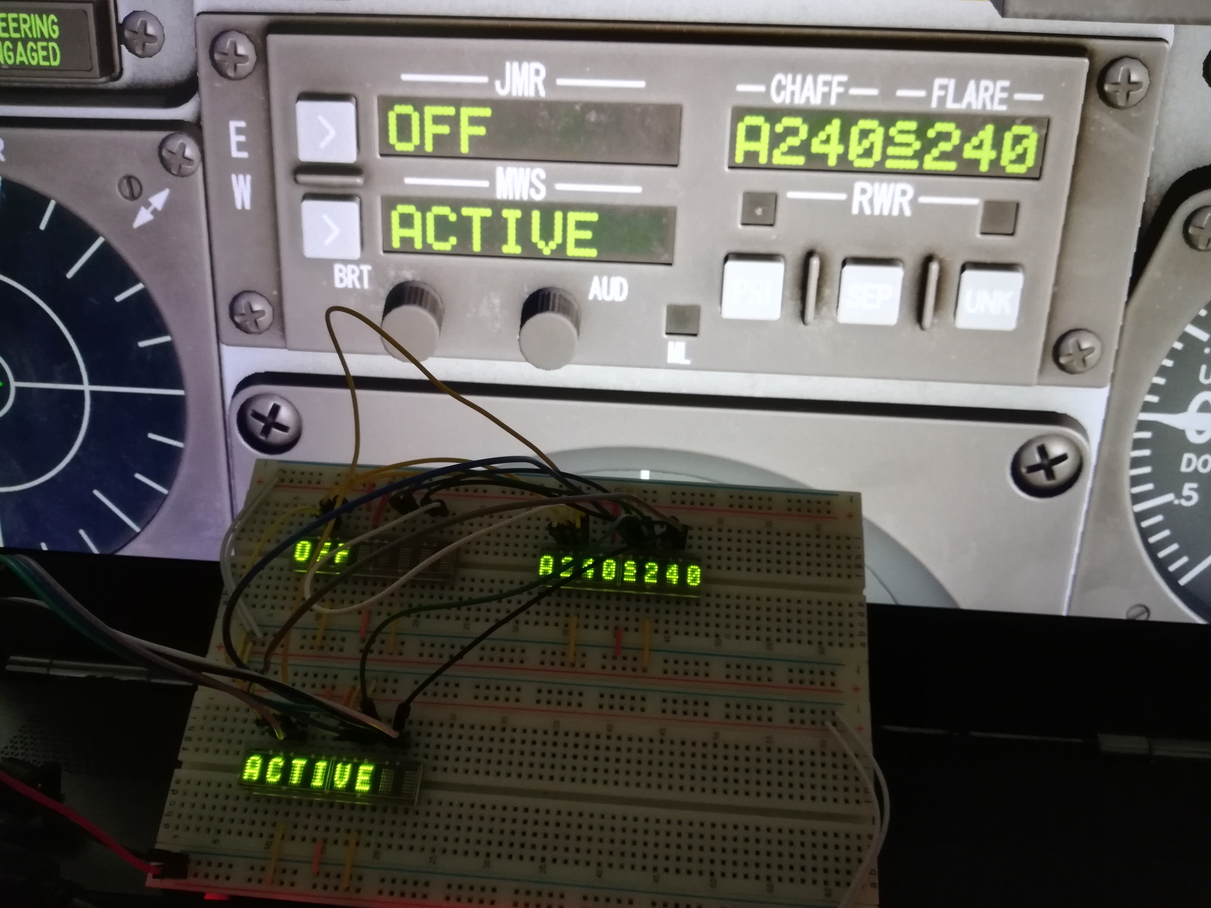
I want to use these displays for the CMSC Panel. By my "proof of concept" I confirm the comfortable brightness settings if using HCMS-297x displays and the LedDisplay library. Just use a standard value for the brightness variable at startup (e.g int brightness = 10) and when running DCS let do the "onCmscBrtChange" command it's work. Regards, Vinc example code from CSMC ... // CSMC set Display brightness to DCS output void onCmscBrtChange(unsigned int newValue) { myDisplay.setBrightness(map(newValue, 0, 65535, 0, brightness)); } DcsBios::IntegerBuffer cmscBrtBuffer(0x10ea, 0xffff, 0, onCmscBrtChange); ... Edit: should be the same for the CSMP when using "onCmspBrtChange" command.

-
I don't have the Viggen and therefore no DCSBios plugin for that a/c. But why don't you use a variable that is TRUE (logical 1) if the AFK light is on and FALSE (logical 0) if it's off? That variable than can be used in combination with the servo output for the throttle. What I mean is, that the servo can only move if your variable is TRUE. Otherwise the throttle can be moved free. Regards, Vinc
-
Hi Rump, update rate is not the best, I think it`s caused by the DCS-BIOS protocol. Speed is round about half a second per page if connected via USB. But I like that kind of vintage style when lines are refreshed from top to down If you want faster refresh, you have to export the monitor display from your GPU. Regards, Vinc
-
I like those little things, simple but very effective
-
Just (jump) wire the display to the Nano and use the same pin numbers like at the Uno. Both boards are pin compatible. Regards, Vinc
-
I think, the slow response of the display is caused by the DCS-BIOS connection. It is even more slower if going the RS485 way. So it's better to stay with USB. Personally I use a NANO for my 4" CDU-Display, it has the same chip like the UNO but is smaller and cheaper. The keypad matrix is driven by a second NANO, connected via RS485 bus. Regards, Vinc
-
For keyboard like things I made good experiences with Arduino Leonardo or Pro Micro (same chip). Regards, Vinc
-
Gary, do you use a TripleHead2go for the monitor setup? What's your frame rate for the sim? Regards, Vinc
-
Anton, depending on your display driver, you may have a look at this site: https://lygte-info.dk/project/DisplayDriver UK.html Regards, Vinc
-
Hello, in principle you got it. But my panels mostly are layered. First layer is a backplate (2 mm transparent plexi glas), holding the mechanics in place. Second layer is of (4 mm) transparent acryl, to enable backlighting. Last layer is white plastics, covered with black foil or paint and engraved. The small button caps can be placed within the middle acrylic layer, that is thick enought to hold them. My caps are CNC milled or printed in white resin. To enable backlighting of the buttons they are painted in grey and CNC engraved. Pushbuttons are available with built in LED, e.g. from here: https://pcflights.com/index.php?route=product/product&path=46_48&product_id=360
-
Universal military aircraft homecockpit project
Vinc_Vega replied to Viper1970's topic in Home Cockpits
Interesting project, I'll like it! I'm also curious how all the different concepts will be merged. Please keep us informed. Best Regards from Bavaria, Vinc -
For the fuel gauge I use the ready made one from PC Flights, the two servos are connected to a 16bit driver board. The OLED display, I integrated, is at the same I2C bus like the servo board, both at the same NANO. Even when controlled over the RS485 bus (not USB) scrolling speed of the OLED is very fast. But that is only an eye catcher if you push the test button. Regards, Vinc Edit: I finally managed to upload a video from the gauge test