Vinc_Vega
-
Posts
641 -
Joined
-
Last visited
Content Type
Profiles
Forums
Events
Everything posted by Vinc_Vega
-
Nice! But please open a new toppic if you have more specific questions. Next would be to find the right font style and size to fit your needs Regards, Vinc
-
Yes, check the dispay's driver. There are many libraries available for arduino.
-
First picture: no chance with LCDs and arduino, but maybe by exporting a screen overlayed by Helios or using a LED matrix (like the Caution panel in the A-10C). Second picture: maybe by using a small LCD or OLED and arduino. Third picture:
-
Here it is for the altimeter with rolling digits: and a modified sketch Regards, Vinc
-
Limaro, in Germany you can order from rs-online privatkunden https://www.rsonline-privat.de/Products/ProductDetail/TE-Connectivity-FSMIJ62BPG04-Taster-Einpoliger-Ein-Aus-Schalter-SPST-50-mA-6-1-x-6-1mm-Solder-Tab-1614539 75 pcs with green LEDs for 71,31€ Grüße, Vinc
-
Hi, if you are using for example the Master Arm in the A-10C (TRAIN - SAFE - ARM), DCS-BIOS already gives the option for 3-position switches. There is no need to define a middle position if neither Pin_A nor Pin_B are LOW. DcsBios::Switch3Pos ahcpMasterArm("AHCP_MASTER_ARM", PIN_A, PIN_B); Regards, Vinc
-
Hi most of us use tactile switches with inbuild LEDs like these: https://pcflights.com/index.php?route=product/product&path=46_48&product_id=360 Regards, Vinc
-
Create an account, you don't have to pay for it.
-
@Roger01: It's the PWM functionality of an Arduino. Use values between 0 and 255 to control a LED brightness. But it's only working on PWM pins. Regards, Vinc
-

PC Flights A10 Flaps, Hyd Press and Fuel Gauges Help
Vinc_Vega replied to Kenpilot's topic in Home Cockpits
I use a PWM driver board, therefore the sketch is different from yours (example from adafruit). But as the values were questioned, I was thinking about modify the code like this: DcsBios::ServoOutput fuelQtyR(0x10cc,PIN, 265, 438); DcsBios::ServoOutput fuelQtyL(0x10ca,PIN, 232, 420); -
PC Flights A10 Flaps, Hyd Press and Fuel Gauges Help
Vinc_Vega replied to Kenpilot's topic in Home Cockpits
Hi Ken, I use a PWM servo driver board for the pcflights fuel gauge, but maybe the values make sense even to your setup. If not, it could be a way to start from and adjust to your needs. #define SERVOMIN_R 265 // 6000 lbs for Fuel Qty Right #define SERVOMAX_R 438 // 0 lbs for Fuel Qty Right #define SERVOMIN_L 232 // 0 lbs for Fuel Qty Left #define SERVOMAX_L 420 // 6000 lbs for Fuel Qty Left Regards, Vinc -
Since almost 5 years I'm using my Stepcraft 420 2nd edition https://shop.stepcraft-systems.com/stepcraft-2-420-construction-kit, controlled by WinPC-NC and am happy with it. EstlCam is a really good post processor to prepare all the traces. For engraving the panels I recommend roundes bits with a radius from 0.2 to 0.5 mm https://www.sorotec.de/shop/Cutting-Tools/sorotec-tools/Engraving-bits/Radius-Router-Bit/ My PCBs were engraved by using 30° V-Router bits like that https://www.sorotec.de/shop/V-Router-Bit-30-.html Regards, Vinc

-
Hi Les, Imported stl model are not chageable in Solidworks but can bee re-engineered! Meaning you can use the dimensions and draw your new part based on the imported one. Regards, Vinc
-
Burns, do you have a CNC router? It's easy to make boards yourself.
-
Hello, you can find measurements for e.g. buttons on the internet, like here: http://www.ehcknobs.com/index.php?id=MI and draw and print it in 3D. Regards, Vinc
-
Hi Rapti, normally there is a "blink" sketch within the arduino sketch folder. But I wouldn´t recommend that, as it uses a "delay" function, causing your arduino sketch to stop for a certain time. Instead of that I would use statements like "if (ltdRArm == HIGH) { ... }" and code snippets from a "Blink Without Delay" sketch, available on the internet, e.g. from here: https://www.arduino.cc/en/Tutorial/BuiltInExamples/BlinkWithoutDelay Regards, Vinc
-
Sure you connect the display to a microcontroller. But how do you intend to connect that to DCS?
-
Do you want to connect the display via RS485 bus too? That might not to be a good idea as it is to slow to refresh the CDU. USB works perfectly. RS485 may work for the button matrix only.
-
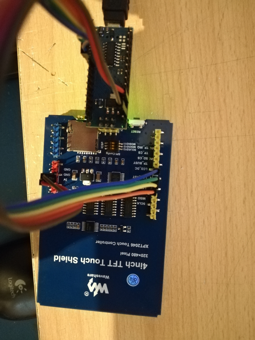
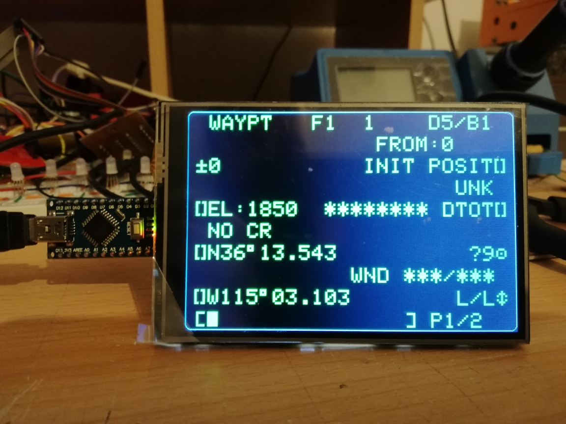
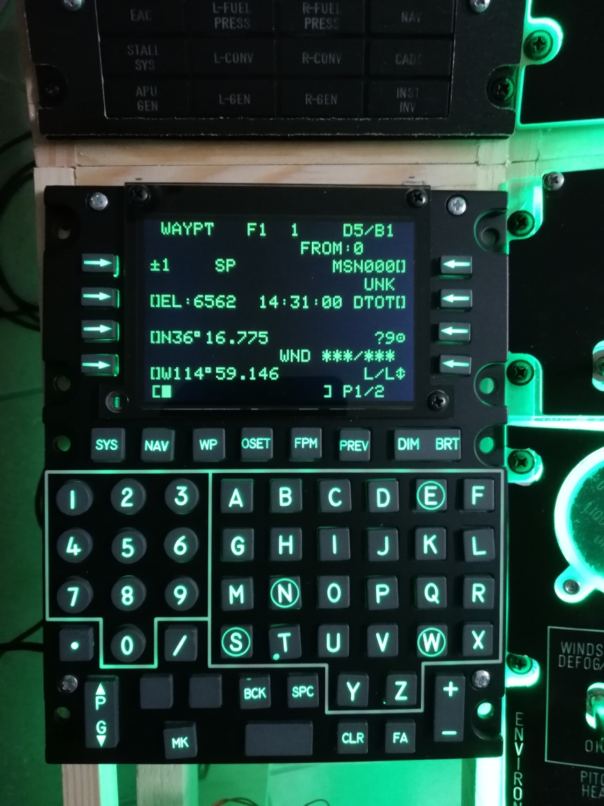
Starting from here: https://github.com/RobinMLi/DCS-CDU-Display I ended up with a 4 inch TFT, driven by an USB powered NANO. Regards, Vinc
-
Try to delete the last separator in your line DcsBios::RotaryEncoder ufcCom1Sel("UFC_COM1_SEL", "DEC", "INC", 3, 2,);
-
I know that 2 and 3 are the pins in use (those with the interrupts at UNO or NANO). I just found out that an additional argument after the pin numbers may solve the problem. That way I did it for the ILS-Panel of the A-10C. DCS-BIOS documentation isn´t right at that point. The default value in Encoders.h seems to be "ONE_STEP_PER_DETENT".
-
Maybe you have a different rotary encoder, based on 2 or 3 increments for the radio channel?
-
Hi Corvidae, I´ve found out that for fixed step rotaries an additional argument has to be used, in my case 4 “steps per detent”. Not like documented, that number of steps per detent must not be in angle brackets. That didn´t work for my setup. Just put it in the curved brackets after the pin numbers, like that: DcsBios::RotaryEncoder ilsVol("ILS_VOL", "-6553", "+6553", 11, 12, 4); Best regards, Vinc
-
I used Fritzing for my CDU PCB with self drawed footprints for the illuminated switches. Unlike Eagle (now Autodesk), Fritzing allows the necessary size for that big board.
-
Thanks, BlackLibrary