Vinc_Vega
-
Posts
641 -
Joined
-
Last visited
Content Type
Profiles
Forums
Events
Everything posted by Vinc_Vega
-
Sir, can you provide a list of deltas between A-10C and A-10C 2 commands (changed or added signals in DCS-BIOS) ? So its easyer to see if or what panels have to be re-programmed. Thanks in advance.
-

DCS BIOS - A10C read data from Gauges to LCD -
Vinc_Vega replied to raptor909's topic in Home Cockpits
Just Put your lcd.print and Cursor Things away from the setup into the loop routine -
Or try fritzing. https://fritzing.org/home/ .
-
It compiles with the Arduino GUI without uploading the sketch to the chip. As I don't have the hardware, I could at least check correct spelling.
-
How about that? It compiles on Arduino but there seems trouble with the line 38, so it`s temporary deactivated DcsBios::Potentiometer pltEmergWingSweepltLever("PLT_EMERG_WING_SWEEPLT_LEVER", A0, false, 0, 385); /* use '#define DCSBIOS_DEFAULT_SERIAL' instead if your Arduino board * does not feature an ATMega328 or ATMega2650 controller. */ #define DCSBIOS_IRQ_SERIAL #include "DcsBios.h" #include <LedControl.h> /* pin 7 is connected to the DataIn pin 6 is connected to the CLK pin 5 is connected to LOAD We have only a single MAX72XX. */ LedControl lc=LedControl(22,26,24,1); /* paste code snippets from the reference documentation here */ //PILOT ARC-159 Frequency void onPltUhfStringFreqChange(char* newValue) { lc.setChar(0,0,newValue[6],false); lc.setChar(0,1,newValue[5],false); lc.setChar(0,2,newValue[4],false); //true=this is the full stop after digit no 3 lc.setChar(0,3,newValue[2],true); lc.setChar(0,4,newValue[1],false); lc.setChar(0,5,newValue[0],false); } DcsBios::StringBuffer<7> pltUhfStringFreqBuffer(0x1248, onPltUhfStringFreqChange); DcsBios::LED pltHookLight(0x12ee, 0x0008, 2); DcsBios::LED pltSwCoolOn(0x12e2, 0x4000, 13); DcsBios::LED pltMslPrepOn(0x12e4, 0x0001, 12); DcsBios::LED pltGunRateHigh(0x12e2, 0x1000, 10); DcsBios::LED pltMasterCaution(0x12e2, 0x0100, 11); DcsBios::LED pltMslModeBore(0x12e4, 0x0008, 7); DcsBios::LED pltSeamLock(0x12e2, 0x0800, 5); DcsBios::LED pltFlapsInd(0x13c0, 0x0fff, 2); DcsBios::LED pltSpdbrkFull(0x13ba, 0x0fff, 3); DcsBios::LED pltSlatsInd(0x13be, 0x0fff, A7); DcsBios::RotaryEncoder pltHsdKnobCrs("PLT_HSD_KNOB_CRS", "-1200", "+1200", 53, 51); // DcsBios::Potentiometer pltEmergWingSweepltLever("PLT_EMERG_WING_SWEEPLT_LEVER", A0, false, 0, 385); DcsBios::Potentiometer pltVuhfVol("PLT_VUHF_VOL", A4); DcsBios::Potentiometer pltUhf1Vol("PLT_UHF1_VOL", A5); void setup() { DcsBios::setup(); //This initializes the MAX7219 and gets it ready of use: lc.shutdown(0,false); //turn on the display lc.setIntensity(0,10);//set the brightness lc.clearDisplay(0); //clear the display //The following series of "lc.setChar" commands are used to display the number 8 in each digit. This allows us to see each that LED segment is actually working. lc.setChar(0,0,'8',false);// The first number...0, means there are no other MAX7219's connected to the one we are using. lc.setChar(0,1,'8',false);// The second number...1, indicates the digit you are sending data too...digit numbering starts at 0. lc.setChar(0,2,'8',false);// The third number in single quotes is the character thats displayed lc.setChar(0,3,'8',false);// The statement... true/false is to turn on or off the decimal point (dp) for that particular digit. lc.setChar(0,4,'8',false); lc.setChar(0,5,'8',false); } void loop() { DcsBios::loop(); }
-
They offer at least 3 types of PCBs. Here`s the close up of the PCB from pcflight`s website. It looks to me, as if the copper filling is +5V and the traces are GND (middle connector). You have to be aware of the 5V supply and the parallel connected LEDs when defining RSet for a MAX7219.
-
But if you have a previous version (e.g. 0.9.3b) the upgrade is still free :thumbup:
-
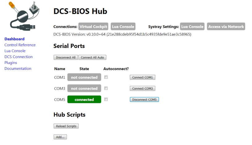
Sorry, what I meant was to isolate the failure. Unplug and plug all arduinos one by one to find the communication issue. Maybe you can isolate the problem to a dedicated COM port. Mostly speed or parity have to be adjusted.
-
Just open the web interface of DCS BIOS (right click the task bar icon) and enable the needed COM ports. To find your issues you can plug and unplug the ports online.

-
Well, because 0xA0 should be the command to enable mirroring, your display seems to have hardware issues. But if that corrects the error, it's a cheap and simple solution. :thumbup:
-
Fine! This forum helped me already a lot! So I want to give back a little bit. It's interesting to know which argument worked for you to demirror the display, is it 0xA0 or 0xA1 ?
-
Hi Les, put in the following line after the initialisation (display.begin(...)) : display.ssd1306_command(0xA0); or display.ssd1306_command(0xA1); to disable and enable horizontal mirroring. like this void setup() { display.begin(SSD1306_SWITCHCAPVCC, 0x3C); display.ssd1306_command(0xA0); display.clearDisplay(); DcsBios::setup(); } . Edit: try this :-) #include <SPI.h> #include <Wire.h> #include <Adafruit_GFX.h> #include <Adafruit_SSD1306.h> #define SCREEN_WIDTH 128 // OLED display width, in pixels #define SCREEN_HEIGHT 32 // OLED display height, in pixels // Declaration for an SSD1306 display connected to I2C (SDA, SCL pins) #define OLED_RESET -1 // Reset pin # (or -1 if sharing Arduino reset pin) Adafruit_SSD1306 display(SCREEN_WIDTH, SCREEN_HEIGHT, &Wire, OLED_RESET); #if (SSD1306_LCDHEIGHT != 32) #error("Height incorrect, please fix Adafruit_SSD1306.h!"); #endif void setup() { display.begin(SSD1306_SWITCHCAPVCC, 0x3C); display.clearDisplay(); } void loop() { display.ssd1306_command(0xA1); // normal display.clearDisplay(); display.setTextSize(2); display.setTextColor(WHITE); display.setCursor(11,15); display.print("DCS A-10C"); display.display(); delay(1000); display.ssd1306_command(0xA0); // mirrorred display.clearDisplay(); display.setTextSize(2); display.setTextColor(WHITE); display.setCursor(11,15); display.print("DCS A-10C"); display.display(); delay(1000); }
-
Hi Les, do you have a code sample for the mirrored text to see what libraries are in use?
-
You are fully right Les. The MAX7219 uses multiplexing. Btw. MOSFETs are also capable to switch so fast that they can be used with PWM pins to dim LEDs. I did this for my 12V panel backlighting.
-
Multiple LCD displays using one Arduino Nano
Vinc_Vega replied to lesthegrngo's topic in Home Cockpits
I think the I2C Bus is to slow to be used for PWM Signals. I'd rather would look for SPI expanders like the MCP23S17 to drive steppers. But I haven't yet. -
Multiple LCD displays using one Arduino Nano
Vinc_Vega replied to lesthegrngo's topic in Home Cockpits
Unfortunately not. As they work with PWM output you should use stepper drivers like the "EasyDriver" boards. -
This is really cool stuff! I always wanted the Hind in DCS but it's SimPit would be a great challange. Thumbs up!
-
Multiple LCD displays using one Arduino Nano
Vinc_Vega replied to lesthegrngo's topic in Home Cockpits
By the way, the PCF8574 chips are not only used to connect displays to I2C but are real 8 bit port expanders. This is a good chip to save arduino in- and output pins. That means, for example 8 switches (2 Pos) can be wired to one PCF and use only 2 arduino pins (I2C). I think, that up to 8 PCF8574 can be connected to one I2C bus and therefore your saved inputs can by multiplyed by 8 (= 64) per arduino. You can also mix the in- and outputs of one PCF so that even a few LEDs can be lit. -
Hi Les, a while ago there was the DCS-BIOS Debug Tool discussed here in a thread. It would have been a good start for exactly that what you (and other builders) want. Unfortunately the development seems to be stopped. https://forums.eagle.ru/showthread.php?t=217428 .
-
Advice on using LED's for warning light panel
Vinc_Vega replied to lesthegrngo's topic in Home Cockpits
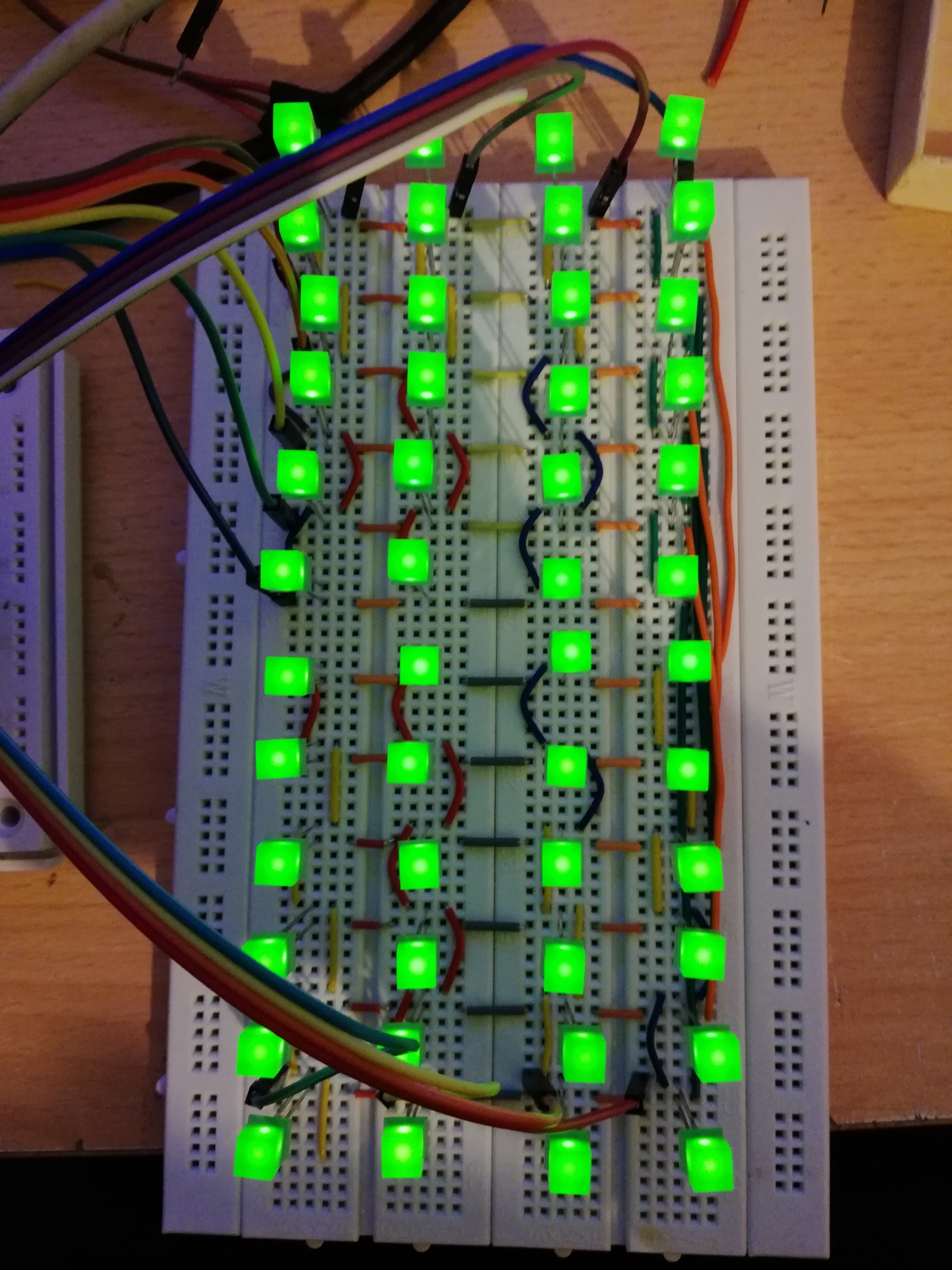
Congrats Les! I built the CLP matrix on a breadboard and got it working with ClayM's layout to proof the concept. Just found out that by using "setIntensity" and two variables the whole CLP easily can be dimmed by the lights control panel. That's cool! These values have to be adjusted by your needs, from 0 (dark) to 15 (full brightnes) // variables to dimm by the LCP "SIGNAL LTS" switch (BRT / DIM) byte BRT = 14; // normal brightnes byte DIM = 5; // dimmedand the object to communicate with DCS Bios // dimm the CLP matrix by the LCP "SIGNAL LTS" switch void onLcpSignalLightsChange(unsigned int newValue) { if (newValue == 1) lc.setIntensity(0,BRT); else lc.setIntensity(0,DIM); } DcsBios::IntegerBuffer lcpSignalLightsBuffer(0x1144, 0x0200, 9, onLcpSignalLightsChange);
-
Advice on using LED's for warning light panel
Vinc_Vega replied to lesthegrngo's topic in Home Cockpits
deleted -
When I'm for the next time in Budapest, I'll give you a call :-) Congratulations and sorry for the late answer, the weekend has been reserved for family stuff ... I think that's to the missing symbols in your font library. I'm not shure if that workaround is the same with your RA8875 driver, but you can try it: I replaced the original gfxfont.c file with the edited glcdfont.c but added the header from gfxfont.c to it. Simply put the attached files into your Documents\Arduino\libraries\Adafruit_GFX_Library directory (original file to be backed up before that). I can not confirme this. Give DCS Bios a little time after loading a new mission to refresh the display (< 10 seconds). To force a refresh switch to an other CDU Page (OTHER, POSITION, STEER, WAYPT) or use the Page Rocker (P / G) to switch to page 2. CDU-Fonts.rar
-
Understand, you want to have the signals sent to a second computer and test your hardware just in time. In the past there was an option to send DCS Bios signals over local network and receive them by an arduino ethernet shield, but I didn't know if that option still exists.
-
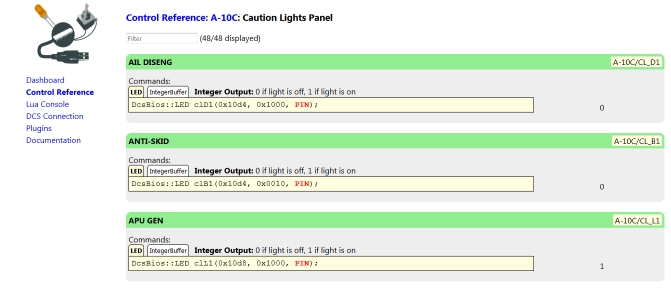
Hi Les, this is exactly what DCS Bios "Control Reference" does when DCS runs in the background. For indications the status is feedbacked by the 0 and 1. The same logic is implemented for switches and their corresponding position numbers. Gauges hand's position is represented by a value between 0 to 65535.
-
Hi Les, it's not that easy because all the following code is based on calculations and the result is than printed by the drawChar statement to the display. I therefore replaced the code from void drawChar to the last DcsBios:StringBuffer statement to print all 10 CDU lines, line by line. That makes everithing a little bit slower but in the end the content from CDU is displayed on the screen. Furthermore I replaced your "clearScreen" commands by "fillScreen" as it won't compile on my PC and gave the text a green color with black background. Except this I let the rest as it was and attache the file to this post. Hope that it will compile on your PC. Maybe the row distances have to be adjustet or the text size has to be reduced according your screen resolution. EDIT: I forgot the text background color in the file, so try to replace the last statement with this: tft.setTextColor(RA8875_GREEN, RA8875_BLACK); and see if it works // --------------------- replacement for the "drawChar" things -------------- // CDU line 1 void onCduLine0Change(char* newValue) { tft.setCursor(12,4); tft.print(newValue); } DcsBios::StringBuffer<24> cduLine0Buffer(0x11c0, onCduLine0Change); // CDU line 2 void onCduLine1Change(char* newValue) { tft.setCursor(12,62); tft.print(newValue); } DcsBios::StringBuffer<24> cduLine1Buffer(0x11d8, onCduLine1Change); // CDU line 3 void onCduLine2Change(char* newValue) { tft.setCursor(12,110); tft.print(newValue); } DcsBios::StringBuffer<24> cduLine2Buffer(0x11f0, onCduLine2Change); // CDU line 4 void onCduLine3Change(char* newValue) { tft.setCursor(12,158); tft.print(newValue); } DcsBios::StringBuffer<24> cduLine3Buffer(0x1208, onCduLine3Change); // CDU line 5 void onCduLine4Change(char* newValue) { tft.setCursor(12,206); tft.print(newValue); } DcsBios::StringBuffer<24> cduLine4Buffer(0x1220, onCduLine4Change); // CDU line 6 void onCduLine5Change(char* newValue) { tft.setCursor(12,254); tft.print(newValue); } DcsBios::StringBuffer<24> cduLine5Buffer(0x1238, onCduLine5Change); // CDU line 7 void onCduLine6Change(char* newValue) { tft.setCursor(12,302); tft.print(newValue); } DcsBios::StringBuffer<24> cduLine6Buffer(0x1250, onCduLine6Change); // CDU line 8 void onCduLine7Change(char* newValue) { tft.setCursor(12,350); tft.print(newValue); } DcsBios::StringBuffer<24> cduLine7Buffer(0x1268, onCduLine7Change); // CDU line 9 void onCduLine8Change(char* newValue) { tft.setCursor(12,398); tft.print(newValue); } DcsBios::StringBuffer<24> cduLine8Buffer(0x1280, onCduLine8Change); // CDU line 10 void onCduLine9Change(char* newValue) { tft.setCursor(12,446); tft.print(newValue); } DcsBios::StringBuffer<24> cduLine9Buffer(0x1298, onCduLine9Change); // --------------------- end of replacement ------------------------- CDU_DISPLAY_LES_Test03c.rar