Irisz
-
Posts
185 -
Joined
-
Last visited
Content Type
Profiles
Forums
Events
Everything posted by Irisz
-
MiG-29 all versions, Damper does not work properly at high speed!
Irisz replied to Irisz's topic in MiG-29 for DCS World
Четвертый опытный (и пятый по счету) самолет, получивший №917, строился с учетом замечаний по первым прототипам. Сборка машины завершилась в сентябре 1979 г., а первый вылет состоялся 15 декабря 1979 г. Этот экземпляр предназначался для определения летно-технических характеристик, характеристик устойчивости и управляемости, отработки системы автоматического управления САУ-451-01. В 1980 г. он был предъявлен на этап «А» ГСИ. В процессе испытаний на 917-м несколько раз подвергалась доработкам система управления. В августе 1982 г. после выполнения 143 полетов самолет был отправлен на завод для оснащения дифференциально отклоняемым стабилизатором (до этого у всех МиГ-29 управление по крену осуществлялось только с помощью элеронов). Облет самолета №917 с новой системой поперечного управления состоялся 21 сентября 1982 г. В 1983-1984 гг. МиГ-29 №917 участвовал в программе специальных летных испытаний по улучшению маневренности и управляемости истребителя на больших углах атаки, о которых рассказано ниже. The fourth pilot (and fifth, by the way) aircraft, which received No. 917, was built in accordance with the remarks on the first prototypes. Assembly of the car was completed in September 1979, and the first flight took place on December 15, 1979. This sample is intended for the determination of summer-technical characteristics, characteristics of stability and handling, development of automatic control system САУ-451-01. В 1980 г. он был предъявлен на етап «А» ГСИ. During the testing of the 917, the control system was modified several times. В августе 1982 г. After completing 143 flights, the aircraft was sent to the factory to be equipped with a differentially deflected stabilizer (until that time, all MiG-29s had roll control only with the help of ailerons). Облет самолетна №917 с новый систем паравсленого управление состоялся 21 сентября 1982 г. В 1983-1984 MiG-29 №917 participated in the program of special flight tests to improve the maneuverability and controllability of the fighter at large angles of attack, which are described below. If it doesn't have a G limiter, why do you have to deal with the characteristics of stability and handling? I'm at proof 3! -
MiG-29 all versions, Damper does not work properly at high speed!
Irisz replied to Irisz's topic in MiG-29 for DCS World
The MiG-29 has hydraulic controls and a SAU-451 three-axis autopilot but, unlike the Su-27, no fly-by-wire control system. Nonetheless, it is very agile, with excellent instantaneous and sustained turn performance, high-alpha capability, and a general resistance to spins. The airframe consists primarily of aluminium with some composite materials and is stressed for up to 9 g (88 m/s²) manoeuvres. The controls have "soft" limiters to prevent the pilot from exceeding g and alpha limits, but the limiters can be disabled manually. Those who think that they can publicly access Russian Soviet military secrets. Where only those documents are published that do not result in prison. At the same time, I published 2 proofs that talk about the limiter, and the others state things, not proofs! I know you want to prove it, but only a real MiG-29 pilot can do it, there is one on the forum! If possible, please describe the operation of the SAU 451 in detail! -
MiG-29 all versions, Damper does not work properly at high speed!
Irisz replied to Irisz's topic in MiG-29 for DCS World
The MiG-29 has hydraulic controls and a SAU-451 three-axis autopilot but, unlike the Su-27, no fly-by-wire control system. Nonetheless, it is very agile, with excellent instantaneous and sustained turn performance, high-alpha capability, and a general resistance to spins. The airframe consists primarily of aluminium with some composite materials and is stressed for up to 9 g (88 m/s²) manoeuvres. The controls have "soft" limiters to prevent the pilot from exceeding g and alpha limits, but the limiters can be disabled manually. -
MiG-29 all versions, Damper does not work properly at high speed!
Irisz replied to Irisz's topic in MiG-29 for DCS World
A developer will respond at some point! I don't think anyone here is a professional MiG-29 pilot, I can be smart too if I want to! I have given enough feedback on the topic! Thank you all for your help! -
MiG-29 all versions, Damper does not work properly at high speed!
Irisz replied to Irisz's topic in MiG-29 for DCS World
It has already been mentioned several times that a compromise is needed in the simulator, if there is no G limiter on the MiG-29 in the future, I will not fly with it anymore! No one is going to spend thousands of dollars for a single MiG-29. There is enough debate about how viable the MiG-29 is! I'm probably getting advice from people who fly from A to B in single player and practice landing, I'm a player who actively plays on PvP servers and I've been destroyed three times because of this problem. 1 out of 10 virtual pilots fly high-altitude, high-speed tactics. If I flew low at 1000 km/h, this problem would never be revealed! That's why the Su-27 is better in everything! -
MiG-29 all versions, Damper does not work properly at high speed!
Irisz replied to Irisz's topic in MiG-29 for DCS World
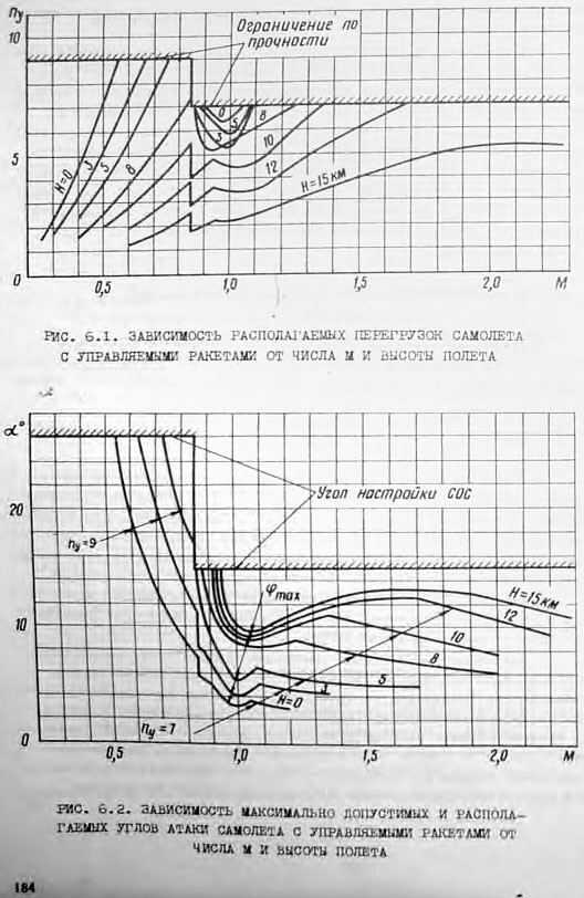
You can see the 9 and 7 G lines on the top graph as you move up in speed! This is not the case with the DCS World MiG-29, you can pull the joystick indefinitely until the plane breaks apart! MiG-29 AoA Indicator and Accelerometer Youtube video I don't think the red parts were invented for decoration! Only the AoA limit is implemented in DCS World, you can see it above, I copied the MiG-29 and Su-27 FM lua, and the MiG-29 has no G limit, only AoA limit! Take this with a grain of salt as I don't have a source, but 7.5 might be the G limit in air-to-ground configuration, and 9G is the limit in clean or air-to-air configuarion The Mig will be like any other jet limit only 5.5 in air to ground because of the pylons There is 7.5rated but could go 9G if you want occasionally. 15 degrees is a typical stalling AOA for an airfoil (generally 13 - 16 degrees), so that's not unusual at all. The G meter, hard so say why there are two marks beyond something like an operational limit and ultimate limit. You will exceed stalling AOA at max G if are at or below Maneuvering Speed. If you're going at top speed and you pull, you will hit max G long before AOA gets to 15 deg. Yes I agree with that. I would bet the small tick mark is a limit with stores and the fat one without. Here, too, these G limits are discussed, and the Graph shows this! -
MiG-29 all versions, Damper does not work properly at high speed!
Irisz replied to Irisz's topic in MiG-29 for DCS World
Here are the load and AoA graphs from the MiG-29 flight manual (or more precisely, its 'Practical aerodynamics' part). The upper graph shows the G limits! One might notice that the official supersonic load limit is 7 rather than 7.5. I'm not sure why is the gauge showing 7.5. The curves indicate loads and AoA that are actually achievable at different altitudes (in km). The boundaries are labelled 'structural limits' (on the top) and 'control system limiter settings' (for alpha). The text explains: The load applies to the mass 14200 kg, whether with or without missiles. For higher mass, the load limit is reduced by 1 g. The lower supersonic limit is explained by the lift losses for trim. (MiG-29 is marginally stable at low speed, but (like nearly any aircraft) is highly stable at supersonic speeds, and part of the wing lift must be used to counteract the strong tail downforce). At M > 0.85, the leading edge droop flaps are stowed, which limits AoA at 15°. At lower speeds, the flaps expand the AoA limit significantly. (There may be further limits; e.g. 13° with a failed SAS (stability augmentation system)). I didn't even have to search for 5 minutes! So the G limiter is not implemented in DCS World and my bug report is important because the game is unplayable above 1500 km/h if I want to fly with a high G load! I am grateful that the forum is full of such helpful people. Criticism always moves you forward! I hope they solve this problem at some point!
-
MiG-29 all versions, Damper does not work properly at high speed!
Irisz replied to Irisz's topic in MiG-29 for DCS World
FMOptionsMiG29.lua stbsk_k_aoa = 1.0 stbsk_k_1 = 1.0 stbsk_pwr = 1.5 cs_wz_DampK = 2.25 hyd_sp_k = 1 Explanation! Stability and Control Parameters stbsk_k_aoa = 1.0: This is likely a coefficient related to the stability or control influenced by the angle of attack (AoA). stbsk_k_1 = 1.0: This is a general stability or control coefficient, which might affect stability in a specific dimension or context. stbsk_pwr = 1.5: This variable probably indicates the power or influence level of the stability system. Damping and Hydraulic Parameters cs_wz_DampK = 2.25: This is the damping coefficient for wz (likely an angular velocity component). It determines how much the system damps oscillations or vibrations in this component. hyd_sp_k = 1: This is a hydraulic system parameter, likely a scaling coefficient. It influences the response or performance of the hydraulic system. Explanation The code aims to set parameters for an aerodynamic or vehicle dynamics model. These parameters control the system's stability, control, and damping characteristics. Each variable represents different physical attributes and influencing factors: The stbsk_k_aoa, stbsk_k_1, and stbsk_pwr variables likely regulate the stability characteristics and performance of the system. The cs_wz_DampK variable defines the system's damping characteristics, which are crucial for damping oscillations and vibrations. The hyd_sp_k variable scales the response or performance of the hydraulic system, which might be important for operating control surfaces, for example. Overall, these parameters fine-tune the aerodynamic and dynamic behavior of the vehicle or system, ensuring the desired performance and stability. FMOptionsSu27.lua cs_Kwz_g = 3.8*0.7 -- ę-ň äĺěďôĺđŕ ďđč âűďóů.řŕńńč (Kny = 0) cs_q_ny_max = 17000 -- 4 ňî÷ęč äë˙ ëîěŕíîé ęđčâîé ę-ňŕ ďĺđĺăđóçęč ďî ńęîđîńňíîěó íŕďîđó cs_q_ny_min = 1600 cs_Kny_max = 0.15 cs_Kny_min = 0.031 cs_q_wz_max = 26000 -- 4 ňî÷ęč äë˙ ëîěŕíîé ęđčâîé ę-ňŕ äĺěďôĺđŕ ďî ńęîđîńňíîěó íŕďîđó cs_q_wz_min = 2000 cs_Kwz_max = 0.72 cs_Kwz_min = 0.4 cs_q_nz_max = 17000 -- âńĺ ňî ćĺ ńŕěîĺ äë˙ ďóňĺâîăî ęŕíŕëŕ cs_q_nz_min = 2000 cs_Knz_max = 0.3*1 cs_Knz_min = 0.1 *1 cs_q_wy_max = 26000 cs_q_wy_min = 2000 cs_Kwy_max = 1.9 cs_Kwy_min = 0.5 -- ę-ňű ÎĎĐ (ÔÔÁ äćîéńňčę) cs_shakeAoA0 = 23 -- ÓŔ íŕ÷ŕëŕ ňđ˙ńęč [ăđŕä] cs_shakeAoA1 = 27 -- ÓŔ ěŕęńčěŕëüíîé ňđ˙ńęč cs_shakeNy0 = 7.5 -- ďĺđĺăđóçęŕ íŕ÷ŕëŕ ňđ˙ńęč cs_shakeNy1 = 8.5 -- ďĺđĺăđóçęŕ ěŕęńčěŕëüíîé ňđ˙ńęč cs_shakeKdAoA = 10*0 -- ę-ň óďđĺćäĺíč˙ (óěĺíüřĺíč˙ ÓŔ ňđ˙ńęč íŕ KdAoA*wz) cs_shakeKdNy = 3*0 -- óďđĺćäĺíčĺ ďî ďĺđĺăđóçęĺ cs_shakeAmpl = 0.4 cs_shakeFreq = 10 Explanation! Pressure and Coefficient Parameters cs_Kwz_g = 3.8 * 0.7: This defines a constant value likely related to the speed and pressure ratio. The comment suggests it is associated with some specific condition (Kny = 0). cs_q_ny_max = 17000: Maximum pressure ratio for a specific condition, probably during high-speed maneuvers. cs_q_ny_min = 1600: Minimum pressure ratio for the same condition. cs_Kny_max = 0.15: Maximum value of a coefficient related to the pressure ratio. cs_Kny_min = 0.031: Minimum value of the same coefficient. cs_q_wz_max = 26000: Maximum pressure ratio for another condition. cs_q_wz_min = 2000: Minimum pressure ratio for the same condition. cs_Kwz_max = 0.72: Maximum value of another coefficient related to the pressure ratio. cs_Kwz_min = 0.4: Minimum value of the same coefficient. cs_q_nz_max = 17000: Maximum pressure ratio for a different condition (likely the travel channel). cs_q_nz_min = 2000: Minimum pressure ratio for the travel channel. cs_Knz_max = 0.3 * 1: Maximum value of a coefficient for the travel channel. cs_Knz_min = 0.1 * 1: Minimum value of the same coefficient. cs_q_wy_max = 26000: Maximum pressure ratio for yet another condition. cs_q_wy_min = 2000: Minimum pressure ratio for the same condition. cs_Kwy_max = 1.9: Maximum value of a coefficient for this condition. cs_Kwy_min = 0.5: Minimum value of the same coefficient. Vibration and Shake Parameters cs_shakeAoA0 = 23: Angle of attack (AoA) at the start of shaking [degrees]. cs_shakeAoA1 = 27: Angle of attack at maximum shaking [degrees]. cs_shakeNy0 = 7.5: Load factor at the start of shaking. cs_shakeNy1 = 8.5: Load factor at maximum shaking. cs_shakeKdAoA = 10 * 0: Coefficient for predicting (reducing) the AoA shaking using KdAoA * wz. cs_shakeKdNy = 3 * 0: Prediction for the load factor. cs_shakeAmpl = 0.4: Amplitude of the shaking. cs_shakeFreq = 10: Frequency of the shaking. Explanation This code sets various parameters for an aerodynamic model, focusing on pressure ratios, stability coefficients, and vibration characteristics: Pressure Ratios and Coefficients: Parameters like cs_q_ny_max, cs_q_ny_min, cs_Kny_max, and cs_Kny_min are used to define the maximum and minimum pressure ratios and their associated coefficients under different conditions. Similar sets of parameters (cs_q_wz_max, cs_q_wz_min, etc.) are defined for other conditions, indicating that the model accounts for various operational states. Vibration and Shaking: Parameters like cs_shakeAoA0, cs_shakeAoA1, cs_shakeNy0, and cs_shakeNy1 define the onset and maximum values for shaking related to the angle of attack and load factor. cs_shakeKdAoA and cs_shakeKdNy are coefficients that predict the shaking behavior. cs_shakeAmpl and cs_shakeFreq define the amplitude and frequency of the shaking. These parameters are crucial for accurately simulating and understanding the aerodynamic performance and stability of the vehicle, ensuring that it can handle different operational conditions safely and efficiently. The provided code snippet does not contain a direct G-limiter. However, certain parameters, such as stbsk_k_aoa and stbsk_k_1, representing coefficients of stability and control, as well as hyd_sp_k, a parameter of the hydraulic system, may indirectly influence the aircraft's load and, consequently, the operation of a G-limiter. Simple! The FM of the Su-27 has a G limiter and protects the pilot's life! And the MiG-29 doesn't have it, so you will die in the MiG-29 because nothing protects you above 12 G load. I think everyone agrees that no one designs an airplane like this, which is deadly for the pilot! I am waiting for an answer from a real MiG-29 pilot or developer! I am grateful to everyone who wants to help! -
MiG-29 all versions, Damper does not work properly at high speed!
Irisz replied to Irisz's topic in MiG-29 for DCS World
I consider it problematic that the MiG-29 can fly at 2,500 km/h, it is dangerous to fly above 1,500 km/h because the airframe will tear apart! You should somehow prove that this is the case in reality. For me, this behavior shows that the Damper is not simulated above 1500 - 1600km/h! Damper means damping, the system pushes the joystick back in critical situations, that is, I think you should limit the joystick even at such high speeds because the airframe will break. Do you think it is reasonable that above 1500 km/h there is no equipment to protect the pilot's life in an airplane capable of 2500 km/h if you panic? It took years before they realized that the springing of the nose wheel was too strong. This is also such a problem! Sitting in an armchair in this simulator, I don't think anyone can tell when you pass the 9G load without looking at the accelerometer, especially if they even launch a missile at you! Unfortunately, Damper malfunctioning will ruin your game. On the Growling Sidewinder server I died three times because of this. I would be more happy with the opinion of a real MiG-29 pilot because there are real MiG pilots here on the forum! -
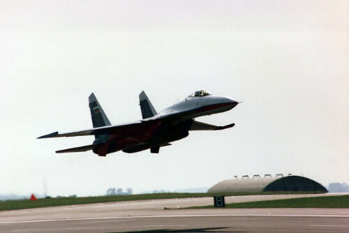
During takeoff, there is no limit on how far you can pull the joystick back! Full afterburner, pull the joystick all the way back, roll, and watch the Flanker's nose as it lifts. When the Flanker starts lifting its nose off the runway, maintain a maximum pitch angle of +10 degrees (at this point, push forward the joystick a bit to prevent the engine nozzle from touching the runway), take off from the runway, retract the landing gear, and enjoy the Flanker love! This procedure lifts the nose up the Flanker off the runway depending on the weight! If your weight is low, sooner, if your weight is high, later, this keeps the pilot and the Flanker safe! Don't try this at Fulcrum! Su-27 special take off technique youtube video At 2:50 you can see this technique I was talking about!
-
Hello dear Fulcrum fans! I made a couple of track files where I show this problem! I've had this game-breaking problem with every version of the MiG-29! I show several times that the MiG-29 cannot be flown at high speed because the Damper does not work above about 1500km/h! You can see how I want to dodge the AMRAAM at high speed, but the Damper does not protect the airframe and it breaks apart! I did such a evasive maneuver with a high G load under both Su-27 and Su-33 and I pulled the joystick separately so that you can see that it works fine here and the aircraft does not break apart at high G load. For me this problem is frustrating and I can't fly such high speed tactics because of it! I have attached the files below so you can see them! MiG-29 Damper not working 1.trk MiG-29 Damper not working 2.trk MiG-29 Damper not working 3.trk Su-27 working fine.trk Su-33 working fine.trk
-
investigating Bug: HOJ broken when target is detected by IRST
Irisz replied to BlackPixxel's topic in Su-27 for DCS World
There is no development without criticism! -
SVP-24 "Gefest & T" complex comprises some sub-systems and one of that is Glonass/GPS receiver/navigation. Besides, all of Russian new/upgraded aircrafts were equipped L-150 Pastel RWR/passive radar that can coordinate radiation targets, feed and guide both air-2-air missiles like R-27P/R-27PE and anti radiation missiles like Kh-31P/Kh-31PE and Kh-58. Upgrading front OLS IRST will add more ability to launch laser-guided missiles like Kh-25L and Kh-29L. Installing a MFD in the cockpit to use optronic guided bombs/missiles like Kab-500KR bomb and Kh-29T missile is very cheap and simple too. Finally replacing new WCS computer to add more new weapons is also very basic thing for all upgraded aircraft. Therefore suppose that upgraded Su-33s with SVP-24 "Gefest & T", new OLS IRST, L-150 Pastel RWR/Passive radar, new MFD in cockpit and new WCS computer at least can use Glonass/GPS guided bombs (but why they need these expensive bombs while they can send dumd bombs to target very accurately?), anti radiation missiles, laser guided missiles, optronic guided bombs/missiles and new air-2-air R-27P/EP missile. Those are so enough for Su-33 in new role of surface attake.
-
Could the developers have an intention to at least correct the range of the radar? Upgrading has been proposed in three stages. The first stage is focused on upgrading air-to-air capabilities and adding some air-to-ground capabilities, by adding a new Baget-55 processor and MVK computer to the existing SUV-27 weapons control system and N001 radar. The new processor and digital computer have data exchange capability through a MIL-STD-1553b equivalent databus. The upgrades to the radar allow use of the RVV-AE/ R-77 AAM. In this first stage the radar can engage two targets simultaneously. The N001 radar also incorporates new modes, and is given the designation N001EM. An air-to-surface mode has been added, capable of acquiring large surface targets from 400km and small-sized surface targets to a range of 120km; it is also capable of terrain mapping (through synthetic aperture), moving target image selection and air-to-surface missile guidance. The Su-30KN can carry up to six Kh-29T TV-guided missiles or up to six KAB-500Kr TV-guided bombs. It can also use the Kh-31A and Kh-31P missiles (up to six can be carried). Three Kh-59M extended-range TV-guided missiles could also be added but their capabilities cannot be fully realized by the first-stage upgrade. To work with the TV-guided munitions, the presently used single monochrome displays are replaced by a single MFI-55 127x127mm color LCD MFD in both the front and rear cockpit. All the modernized aircraft with be equipped with L005S Sorbtsya ECM pods on the wingtips. Also added in the first stage is the A737 GPS, and a bolt-on in-flight-refueling probe. The proposed second stage of upgrading is more sophisticated. The existing N001 radar’s twist-cassergrain antenna will be replaced by a new ‘Pero’ passively scanned, phased array antenna, developed by NIIP. This increases the radar’s range by 20-25%, as well as offering track-while-scan and multiple target (up to six) engagement capability. ECCM capability is also improved. The modified radar will be able to track ground targets, but its resolution is believed to be no higher than about 20m. Therefore, only large ground objects could effectively be targeted by the Kh-29T missile's TV seeker. Laser-guided Kh-29L missiles can also be carried, but the crew would only be able to launch them from a dive, using the existing IRST. The OLS-27 IRST is presently only an air-to-air system, so the system's software will be changed, and an illumination mode will be added to the existing laser rangefinder. The OLS-27's capability to detect ground targets is relatively poor and its mount in front of the cockpit restricts the look-down angle, which is why the system can be used only in a dive and only with missiles, so there will be no capability to direct free-fall laser-guided bombs. Also in the second stage, aircraft will receive a ‘glass cockpit’, with three MFI-68 and two MFI-55 LCD MFDs replacing the analog instruments in each cockpit, as well as HOTAS control. In the proposed third stage, the existing radar will be completely replaced by a new phased array radar. It will significantly enhance the aircraft’s air-to-ground capabilities through the use of a Doppler beam-sharpening mode and a synthetic-aperture mode. The aircraft will also be equipped with the new SAPSAN targeting pod, designed by UOMZ. It will have FLIR and TV channels integrated with a laser rangefinder/ illuminator, with a much larger field of view, enabling use of laser guided munitions from both a dive and horizontal flight. This is the most important part! The first stage, like R77 capability, plus some air to ground modes, sounds like a dead ringer for the same system already used in the PLAAF SU-27SK/UBK/J-11, which Kanwa described as the "N001E" aka Zhuk PD. (Notwithstanding if some Zhuk-27s were used in some SK or J-11). With additional air to ground modes, the same system also sounds like a dead ringer for the one used in the SU-30MKK, which has been called with many names, N001ME, N001VE or N001VME. In fact the rest of the paragraph pretty much describes an SU-30MKK, except that the MKK uses four color CRTs, two in the front, and two in the rear. PLAAF as a testing ground? Why not...
-
You can read more about it here: https://apps.dtic.mil/sti/pdfs/ADA509444.pdf Unfortunately, the R-77 missile has some disadvantages!
-
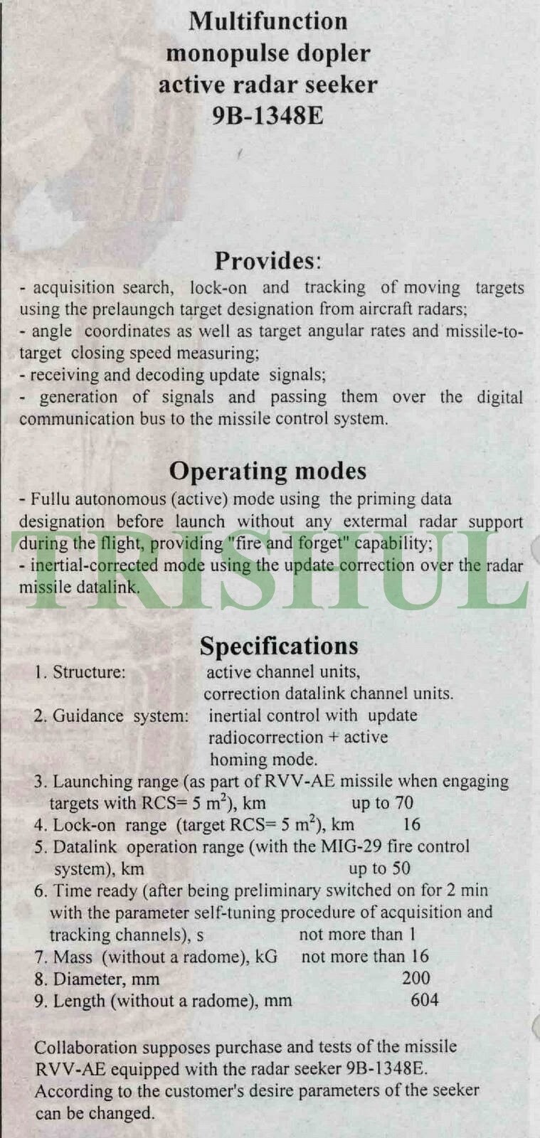
Help for the operation of the RVV-AE missile! These are not secret documents, anyone can get them if they know! https://epizodsspace.airbase.ru/bibl/k-r/1993/8-avia-rak.html Наведение ракеты комбинированное: командно-инерциальное на начальном и активное радиолокационное самонаведе ние на конечном участке траектории. Переход на второе осуществляется по сигналу бортовой вычислительной маши ны, которая определяет дистанцию захва та цели головкой. После перехода на самонаведение линия коррекции полет ных данных ракеты с самолета-носителя продолжает формировать математичес кую модель цели. В случае ее потери на траектории организуется повторный по- иск с использованием этой модели. Схема атаки выглядит так. Самолет носитель производит поиск, захват и со- провождение целей своей бортовой ра диолокационной станцией. (Число итаку емых целей является характеристикой самолетной станции, а ракета сконструи рована таким образом, что любая из под вешенных под носителем может быть пущена по своей цели). Примерно за 10 секунд до входа в зону разрешенного пуска или по команде «Пуск» ракета на чинает работу в предпусковом режиме и получает от носителя информацию о цели, По команде «Пуск» включается автоном- ное питание, запоминается информация о параметрах носителя и цели, разаррети руклся рули. ли. Им дается предварительное стклонение для безопасного отделения ракеты от носителя. Если она располага ется на рельсовой пусковой установке, то сразу после этого происходит поджиг двигателя, а если на катапультной, то сначала срабатывают толкатели, отделязо- щие ракету от самолета, а затем с некото рой, зависящей от тактической ситуации, задержкой включается двигатель. После удаления ракеты от самолета на безопасное для него расстояние (150 300 м), изводится механизм взрывателя. При этом, в случае стрельбы на минимальной дальности, командно- - инерциальное наведение не использует ся, а сразу по сходу включается активная головка. Во всех режимах применения исполь зуется метод модифицированного про порционального наведения. А в условиях организованных помех, при которых бор- товая радиолокационная станция носите ля не может обеспечивать ракету сведения о дальности и скорости сближения с целью, наведение происходит по специальным траекториям. (В головке самонаведения ракеты реализована также возможность пассивного наведения на источник по мех, совмещенный с целью). По сравнению с ракетой AMRAAM РВВ-АЕ имеет более высококачествен ную диаграмму направленности антенны головки самонаведения и за счет этого она обладает более высокой эффектив ностью пораження малоразмерных ни зколетающих целей на догонных курсах. The missile guidance is combined: command-inertial at the initial stage and active radar homing at the final part of the trajectory. The transition to the second is carried out by a signal from the onboard computer, which determines the target acquisition distance by the head. After switching to homing, the missile flight data correction line from the carrier aircraft continues to form a mathematical model of the target. If it is lost along the trajectory, a repeated search is organized using this model. The attack pattern looks like this. The carrier aircraft searches, captures and tracks targets with its onboard radar station. (The number of targets to be attacked is a characteristic of the aircraft station, and the missile is designed in such a way that any of those suspended under the carrier can be launched at its target). Approximately 10 seconds before entering the authorized launch zone or upon the “Start” command, the missile begins operation in pre-launch mode and receives information about the target from the carrier. At the “Start” command, the autonomous power is turned on, information about the parameters of the carrier and the target is stored, Rasarreti took the helm. whether. They are given a preliminary declination to safely separate the rocket from the carrier. If it is located on a rail launcher, then immediately after this the engine is ignited, and if on a catapult launcher, then the pushers are first activated, separating the missile from the aircraft, and then with some degree, depending on the tactical situation, The engine is switched on with a delay. After the missile is removed from the aircraft to a safe distance for it (150-300 m), the fuse mechanism is fired. At the same time, in the case of firing at a minimum range, command-inertial guidance is not used, and the active head is immediately turned on. All application modes use a modified proportional guidance method. And in conditions of organized interference, in which the carrier’s onboard radar station cannot provide the missile with information about the range and speed of approach to the target, guidance occurs along special trajectories. (The missile homing head also includes the ability to passively target a source using fur combined with the target). Compared to the AMRAAM missile, the RVV-AE has a higher-quality radiation pattern of the homing head antenna and, due to this, it has a higher efficiency in hitting small-sized low-flying targets on catch-up courses. 5. Datalink operation range (with the MiG-29 fire control system), km up to 50 I am convinced that this datalink channel with a range of 50 km does not exist in DCS World, which is on the MiG-29S to control the RVV-AE! So it is completely unnecessary to talk about the silent start, which is not detected by the opponent's RWR! The Flaming Cliffs product is too arcadey to use RVV-AE! I think many of us are fans of Flanker and Fulcrum and we would be happy if the development of DCS World was not one way and if the developers paid more attention to the Flaming Cliffs product, because the game is broken at some points and with these planes it is frustrating to wait years for something to happen!
-
investigating Bug: HOJ broken when target is detected by IRST
Irisz replied to BlackPixxel's topic in Su-27 for DCS World
It won't play the track file for me! MiG-29S flies instead. He also uses ECM interference, the radar lock above 50 km is rejected because of the interference! It doesn't matter at what radar repetition frequency I follow the target. The default N001 radar repetition frequency operating principle is that in ILV mode, the IRST is automatically activated if the radar loses lock and the IRST has enough power to track the target. In Hi and MED radar repetition frequency mode, this does not work if the radar loses the target, IRST must be turned on manually. (this is the problem with Flaming Cliffs Flanker and Fulcrum) This should be fixed by ED and should be automatic in all radar repetition frequencies of the FC3 Flanker and Fulcrum types. We do not have the radar repetition frequency displayed on the Flanker HUD display under radar lock, we cannot track what repetition frequency the radar uses. In reality, the Flanker works like this, the pilot can see on the HUD display at what frequency the radar repeats during target tracking. In Fulcrum, this is done with a switch, but the HUD display does not show it. Flaming Cliffs is incomplete and fantasy based in several areas, I think this is a good suggestion. There is, however, an even better option, although it requires development! real ECM interference should appear on the HUD display, not fantasy-based as in DCS World, as it can be seen here in the picture on the Flanker HUD display! We also deserve care, not only NATO pilots, who are loved in every patch!