JCook
-
Posts
461 -
Joined
-
Last visited
Content Type
Profiles
Forums
Events
Everything posted by JCook
-
I would also be interested in a complete set of knobs for the A10 - please put me on the list.
-
What VRS has accomplished in FSX is truly amazing and with their new TacPack it will be even better. The biggest problem with the VRS SuperHornet is that it is FSX and is limited by that environment. I've got the FS9 and FSX versions of the plane and gave up on them when the DCS A10C came out - the last problem I had with the F18 was it wouldn't take off. Followed all the correct steps - but they have so many weird setup constraints to get that palne to work - when I want to fly a differenet FSX plane I mave to reconfigure everything. DCS A10 just works flawlessly. Having said all that the VRS FA18 programmers are very, very good and could contribute much to a DCS implmentation of the FA18.
-
I posted this in another thread and hadn't gotten a reply - does anyone know the 'official' height of the joystick in the A10C. That is from the top of the stick to the aircraft floor?
-
How To: Build a A-10 flight panel controller
JCook replied to TigersharkBAS's topic in Home Cockpits
I'm guessing I'll probably use several boards to do a full cockpit so I can try the Leo Bodnars board next. -
Thanks hog driver - if you have a diagram of the electrical panel - dimensions and measurements that would be helpful. I've found one pdf file in the forums that has the basic shape. If you've got one thats more detailed that would help. The best schematic I have is the fuel panel it seems to have every dimension needed. That one and the electrical diagram will be going to the CNC shop for cutting as soon as I can get a quote from them.
-
Surely someone must know the correct height of the joystick in the A10C -
-
14 gauge - got it. Just ordered a USB interface card. Ok I found some EL sheet suppliers. Do these need to be green? Are they wowered separately from the USB interface. Can you point me to any DCS posts on this topic?
-
How To: Build a A-10 flight panel controller
JCook replied to TigersharkBAS's topic in Home Cockpits
Tigershark - Thanks for that video I'm going to order the GP-Wiz40 and use it for my first panel project - the electrical panel. A few questions: What type of wire should I use? I think they are listed by gauge type, right? Are there any other connectors or components - other than the switches that I need? Thanks -
Thank you all for the help. I am going to start small with one panel (electrical) and get that working correctly. There is much to learn. I'll look into the EL sheets and their lighting - hadn't seen anything yet on those. Deadman you pointed out the milspec for the back panel was 0.62mm - does that equate to a gauge number for aluminum - like 16 gauge etc? I am working on a temporary setup for my HOTAS, MFDs, monitor and pedals while I build my pit separately. So I can enjoy and keep progressing on the sim independent of the pit. The electronics part is going to be interesting - my current knowledge doesn't go much beyond flicking a lightswitch. I should get a good book on basic wiring I guess. I appreciate the support from the experts - Thanks.
-
I've got the TM WH HOTAS and am wondering what the actual height of the joystick is in the real A10C. By that I mean measured from the top of the joystick to the floor of the A10C cockpit. Anyone know?
-
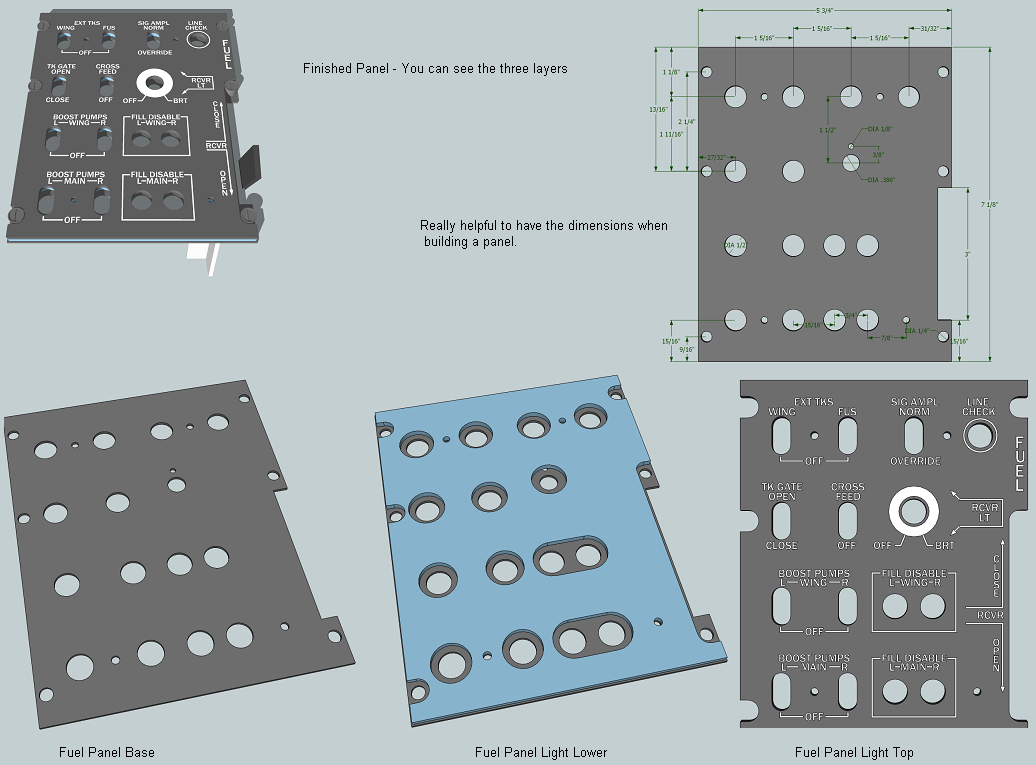
I am a complete newbie on designing, fabricating, building and wiring sim panels. I’ve read several hundred posts on cockpit building wiring and panel building in the last few days and it is overwhelming. I’m planning on building an A10 sim pit using the plans and information in these forums. The talent on these forums is amazing and helpful – and to be honest I am hoping to buy most of the components I need for my A10 pit. But I do want to learn to build panels and wire them for use with the A10C. It’s a steep learning curve and despite all that I have been reading some basic information is eluding me. I am hoping someone might explain this in very simple step-by-step instructions – I have visited and read many of the externally referenced resources mentioned in the forums and I am still not getting it. The example I have here is of the fuel panel. There are three layers and fortunately with this panel a diagram with dimensions was provided. Most of the panels with their dimensions seem very hard to come by. So here is a plea for more panel dimension diagrams. (Please see attached file) So let me ask some simple questions – the more detail you can provide the better. Fuel Panel Base I assume his is the piece that actually gets screwed into the rail system since the other layers are attached to the top of it. Q: What material is the base made from? Q: What is the thickness? Q: Is this a CNC cutting process? Fuel Panel Light Lower This is slightly smaller in dimension and has larger cutouts for the switches. It is called a light layer so I’m assuming this is where we get the backlighting some how. Q: Is there lighting some how attached or diffused to this layer? Q: What material is this made of? Q: What color is it? Q: What is the thickness? Q: How is it attached to the Base panel (glue? – what type) Top Panel This panel has all the labeling and cutouts for the switches. It appears the switches would be mounted (screwed down) below this level – I’d guess on the middle light level. Q: What material is this made of? Q: What type of paint / finishing do you use for this? Q: What is the thickness? Q: How is it attached to the Light panel (glue? – what type) Q: How does the lettering get etched into the surface? Q: Some panels have labeling that is always white – while other lettering glows green (backlit) as with the TM Warthog HOTAS Throttle panel. How is that accomplished? If you can help me with these questions I would really appreciate it – I’m really trying to understand the process. If I can get this down and build a simple panel I can go on from there. The first panel I plan on building is the power panel (battery, inverter, etc.) Thank you for taking the time to explain this. John

-
That original link appears to be dead - can you please repost or send me the file? Thanks
-
pitbldr You mentioned you built the keys for the CDU. Can you describe what they are made of, how they were made, how you lettered them? This stuff is still very much techno-magic to me. I've spent about 8 hours today reading posts trying to understand this stuff. Thanks. John
-
How To: Build a A-10 flight panel controller
JCook replied to TigersharkBAS's topic in Home Cockpits
Thanks for these helpful videos. I know ZERO about elctronics and wiring, but using your tutorial I am going to build my first A10C panel: The power panel (battery, inverter, etc.) Its been very hard to find the dimenstions for these or the other panels but I'll take my best guess on the sizes. What type of wire (gauge) do I need to use? Do you use a different color for each swich position and for ground? I'm going to build one panel at a time - get it working and then go on to the next panel - years from now when I've got all the panels done I'm assuming I will have several USB interfaces setup in the pit. There is a lot of swiches - maybe two interfaces per side and one for the front panel. Any problem with the sim recognizing more that one USB interface board? Thanks John -
Reactorone I've downloaded your files for the panels - such as the AN_ARC_164 UHF - there are two files in the zip a TIF Image and and EPS file. I open the TIF but I am not familiar with the EPS file format - what does it show? Secondly are the TIFF panel images to scale? If I cut them out are they ready for mounting? Third each panel looks like it has three layers can you describe what each layer does, their thickness and how they are attached Finally it would be very helpful if you had a parts list for the various knobs and switches you are using - and a supplier. This is awesome work - looking forward to actually building these panels - MUCH THANKS for all the work you are doing. John French Translate ----- J'ai téléchargé vos fichiers pour les panneaux - tels que l'UHF AN_ARC_164 - il ya deux fichiers dans le zip d'une image TIF et et le fichier EPS. J'ouvre le TIF, mais je ne suis pas familier avec le format de fichier EPS - Que faut-il montrer? Ensuite sont les images TIFF du panneau à l'échelle? Si je les couper en sont-ils prêts pour le montage? Troisième chaque panneau dirait qu'il a trois couches pouvez-vous décrire ce que chaque couche ne, leur épaisseur et comment ils sont attachés Enfin, il serait très utile si vous aviez une liste de pièces pour les boutons et commutateurs différents que vous utilisez - et un fournisseur. Ce travail est impressionnant - impatients de construire réellement ces panneaux - MERCI BEAUCOUP pour tout le travail que vous faites.
-
Thanks y2kiah. Your work is absolutely awesome - THANK YOU so much for sharing with the community. I am an absolute beginner on this stuff but with your help and the help of others on this forum I'm going to build this pit. So those dfx files are all the CNC shop will need (with the depth of cut explanation)? It just seems funny to me to see a diagram without dimenstions and angles - it must be CNC magic :-) I've seen alot of your 3-D panel pictures (radio, oxygen, lighting, etc) and know you've mentioned several times you'll release info once you're done. Are these panel diagrams / dimensions going to be released anytime soon? Will they also be CNC? I've lined up some local resources for making these once I can get dimenstions. The panels are a bit confusing there appear to be several layers which include an acrylic lighting layer (how does that work?) a back piece and the front piece with laser eched lettering. No idea how any of that works - a step-by-step guide on this would be really helpful. Happy to buy any of these detailed instructions if you decide to sell them - I know you've put alot of work into this. What did you this of my simkits gauge idea from my recent post? John
-
I'll show those .dfx file to the CNC shop and see if they have enough info to make the cuts. Has anyone considered using one of the gauge kits from simkits (http://www.simkits.com/products.php?groupid=40) for the analog gauges? I was thinking a custom A10 face could be cutout and placed in the round dial. I found a few more resources for switches: http://www.digikey.com/?curr=USD http://www.mouser.com/ http://www.newark.com and http://www.alliedelec.com/sap
-
Okay but the left and right consoles are made from wood correct. I had though my carpenter would just take the plans and make the cuts. Are you saying I give these .dfx files to a CNC shop they plu them into their machine and it makes the cuts? - is it that easy?
-
Well - thats a good point. I'd still like to fly those other theatres someday - we can always make them interesting in themission editor I suppose.
-
Someday when I've learned enough about flying the A10C I hope to do some of the missions and campaigns. In general if I'm playing the role of a US Air Force pilot who is my opponent? Russia? Which bases are their's and which are the US allied bases. I'm just not familiar with that part of the world or the geopolitics of the region. It seems and Iraq or Afganistan Theatre would have been more realistic.
-
I've downloaded y2kiah's .dfx files showing right side and left side cutouts. They're real nice - but something seems to be missing, and forgive me I didn't get an A in highschool shop class, but don't there need to be dimensions to go along with those shapes? How can I take those shapes to a carpenter and ask him to cut them - he's going to want to know the lengths and angles right? or am I missing something? I've also been extremely impressed with the individual panels and hope they will be be released with their dimensions soon. Thanks
-
How To: Build a A-10 flight panel controller
JCook replied to TigersharkBAS's topic in Home Cockpits
would the momentary switch physically stay in the up position when you flip it on? -
Same thing happened to me when running this - it just keeps ataking you through this calibration loop. I ended up closing it after a while. New calibration does seem a bit better - but not perfectly centered yet. didn't see any numbers indicating positions - maybe that shows up in the target software?
-
yallu - you may want to just buy a real E6B. They aren't very expensive and you should be able to find one at most aviation stores. Try here: http://www.asa2fly.com/search2.aspx?keywords=e6b John
-
No - I think this will work. I'm not talking about white text on black, I'm talking about the outline of black background on transparency the lettering themselves will be transparent.