0414 Wee Neal
-
Posts
338 -
Joined
-
Last visited
Content Type
Profiles
Forums
Events
Everything posted by 0414 Wee Neal
-
board updates - RS485 hi silly question time, with all my panels connected via rs485 modules and NANOS if i need to update the sketch on a panel, can this be done via network or do i have to plug in via usb? main reason is so i can plan how frequently i would physically access the boards. thanks neal
-
Thanks John I am assuming that what we are doing is to extract data from DCS on the radio freq, with the encoders linked to sim to change frequency there? Thanks for the code it means nothing at the moment, so lots of reading to do! Neal
-
More progress Hi I have been working slowly on my panels, more progress, lots more soldering to go! Neal

-
Hi I am not sure how best to explain what I want to know/learn not being a programmer or expert in electronics, so I will put it in laymans terms; please excuse any faux par’s in descriptions! Stage one – I have built my 1st VHF panel and have wired all of the buttons and switches etc and connected these to an Arduino Nano, this in turn is wired to an RS485 module – All simple so far! Stage two – I have installed a 6 digit 7 segment display and wired this to an MAX 7219 module and connected this to the same Nano as above…All reasonably simple (I have already setup my Caution Light panel and have this working, so proved the design concept). Stage three – I have written a sketch which incorporates the code for the VHF radio for each button, switch, encoder etc and uploaded this to the Nano. This all works and buttons operate as they should in DCS Warthog; happy days! Stage four – Getting the 7 segment displays to work – Here I am struggling. I am not asking anyone to write my sketch as I would like to write this myself, but frankly I have no idea where to start? Can anyone help by answering these questions: a. I have the MAX7219 datasheet and I am starting to understand, through your tube tutorials and Jeremy Blum text book what it all means. By doing this I can get the displays to light up and say help or 5 etc. 1). What is the next step in being able to tell the displays what to display? 2). Is this done by DCS BIOS? If so is this part of the code - void onVhfamFreq1RotChange(unsigned int newValue) { /* your code here */ } DcsBios::IntegerBuffer vhfamFreq1RotBuffer(0x11bc, 0x07f8, 3, onVhfamFreq1RotChange); 3). Where it says ‘your code here’ what is this code really doing – In laymans terms please. Sorry if this seems a dumb set of questions, but I am struggling to understand what I am asking the displays to do, which is a fundamental starting point. Cheers Neal
-
cdu Hi great build, far better details than I have achieved! I would be very interested in following your CDU construction, specifically what screen and buttons you have used? I am about the same stage as you (after 3 years) and I am wiring my panels currently, using DCS BIOS which is an absolutely inspired programme. I have at the moment a working CMSP, caution light panel, UFC, electrical, fuel, armaments. I have not tackled the CDU at all, as the screen seems to be a problem to find. I did chuckle at your comment about enjoying the building more than the flying, as that is how I feel at the moment. I have also gone down the 3 projector route and recently installed 3 Benq 1070 HD beamers, the image is stunning. Regarding the front console, does that work well with Helios, I have concerns on the depth of the panels with switches creating a 'tunnel effect' with the thickness of the wood build up? Neal
-
Updating the Updates Hi [FSF]Ian thanks for the update: Released v0.2.4 of the Arduino Library. fix DcsBios::ActionButton (buttons would get stuck) fix DCSBIOS_RS485_SLAVE on ATMega328 controllers When I load the v0.2.4 into IDE, I assume I delete reference to the old library (v0.2.3)? Do I then need to reload my sketches for each panel or is that it in terms of library updates? Sorry if this is a silly question. Regards Neal P.S. Having great fun using this excellent programme!
-
Hi Pete, I have constructed my panels in layers: a, Layer 1 is the face plate and is in 1.5mm laserable laminate which has a black finish and white base b. Layer 2 is a green acrylic 3mm thick. c. Layer 3 is a special light panel taken from a flat panel LED light, this is fitted with a strip of LED on two sides, this light panel refracts light to create a single light source. The coral draw files are of layers 1 to and 3. Neal
-
Hi Pete I have my panel files in Coral Draw if that would be useful starter? Neal
-
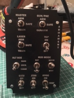
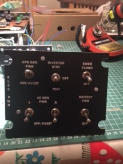
Hi Pete I think it is important to state that my cockpit is not intended to be an exact facsimile of an A10C, I am trying to get the look similar (but as close as possible!). The buttons I have used are: 10pcs White Square Cap Momentary Tactile Tact Push Button Switch 12 x 12mm x 8mm by sourcingmap Link: http://www.amazon.co.uk/dp/B0087ZF6ZE[/ I am using a dymo label machine to create the lettering, which is on a metalic tape. I hope that helps, let me know if you need anything else? Happy building. Neal
-
[FSF]Ian thank you for your response, much appreciated. The Nano and Uno board have 14 digital pins, which for some panels is insufficient, I understand I can use the Analogue pins as digital, would this require me to write any additional code i.e. pinMode(A0, OUTPUT); digitalWrite(A0, HIGH); if that is required, would I enter this under void setup? Any advice greatfully received? Thanks Neal
-
VHF PANEL Hi I am now looking at my 2 VHF panels and was wondering if anyone had written a sketch, specifically for the interface with a MAX 7219 chipset? Thanks Neal
-
RS485 Network - The first step Hi I have decided to attempt to setup all of my panels by using the MAX485 chip and as such have purchased 6 to begin with. I am reading up on the topology and have so far made the following assumptions/choices: a. I am going to use Cat5 as the networking cable - I am not sure yet how to wire in the 120ohm resister; more reading needed! b. I am going to use Arduino Uno as the slave boards and will have 3 Mega boards as 3 masters. This will be left, right and dashboard. Not sure yet how many Uno's I will need. I am wiring each panel to a terminate on a prototype board fixed to the back of each board. These 'junction boards' will then have a connecting cable direct to each Uno, in this way the panels can be removed without disrupting the Arduino connections. I THINK THAT MAKES SENSE? c. I am wiring each panel and then setting up the sketch for each panel independently to ensure they work. Once all tested I will group them together to effectively 'fill up' each Uno pins. This is where I am not sure how then to setup: I am assuming that if I setup a new skeetch using the slave template and then add the sketch for all panels connected to each Uno, effectively making it a looooong sketch with all switches added in. IS this a correct assumption? Any thoughts or comments would be greatfully received please. A it scared by the birds nest of wiring I am creating and how the heck I will record how it all comes together; any suggestions? thanks as always Neal
-
Success Hi I am please to say that after replacing the failed led, the issue of the leds lighting up dimly dissappeared. It appears that when one of the Leds within the matrix fails it creates some kind of electrical feedback to the other leds in that ROW. It did not appear to have the same effect in the column. Thank you for your support, I now have a fully functioning CLP: YIPPEEEE! Best wishes Neal
-
Hi John tried the new sketch, no change. One of my led's was not working so i have swapped that out, not sure if that could have been affecting anything. I have gone through and checked joints and remade a few dodgy looking ones. The dim leds were on te same row as the non functioning one. I will check on dcs pc tomorrow. thanks for the assistance. Neal
-
Hi once i had the face plates and back plate done, mounting the switches took me about 2 evenings for the electrical panel and about 4 evenings for the UFC. The wiring on the electrical took me 2 evenings and UFC 6 evenings (an evening for me between bathing kids and eating is about 90minutes). The setup for Arduino and DCS Bios was the easiest and quickest at about 1 evening each. I have also built the Caution panel, but that was a pig to do and took me 3 weeks of evenings to wire. The DCS Bios about 3 evenings. To be honest I manufactured the faceplates late 2015, but until DCS Bios came along I struggled with learning .lua, which was veryy difficult for me. Happy to provide any further information if you want? Regards Neal
-
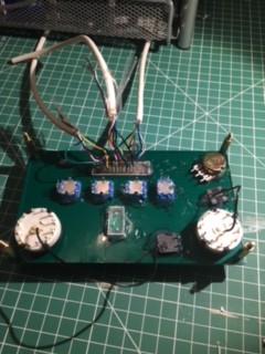
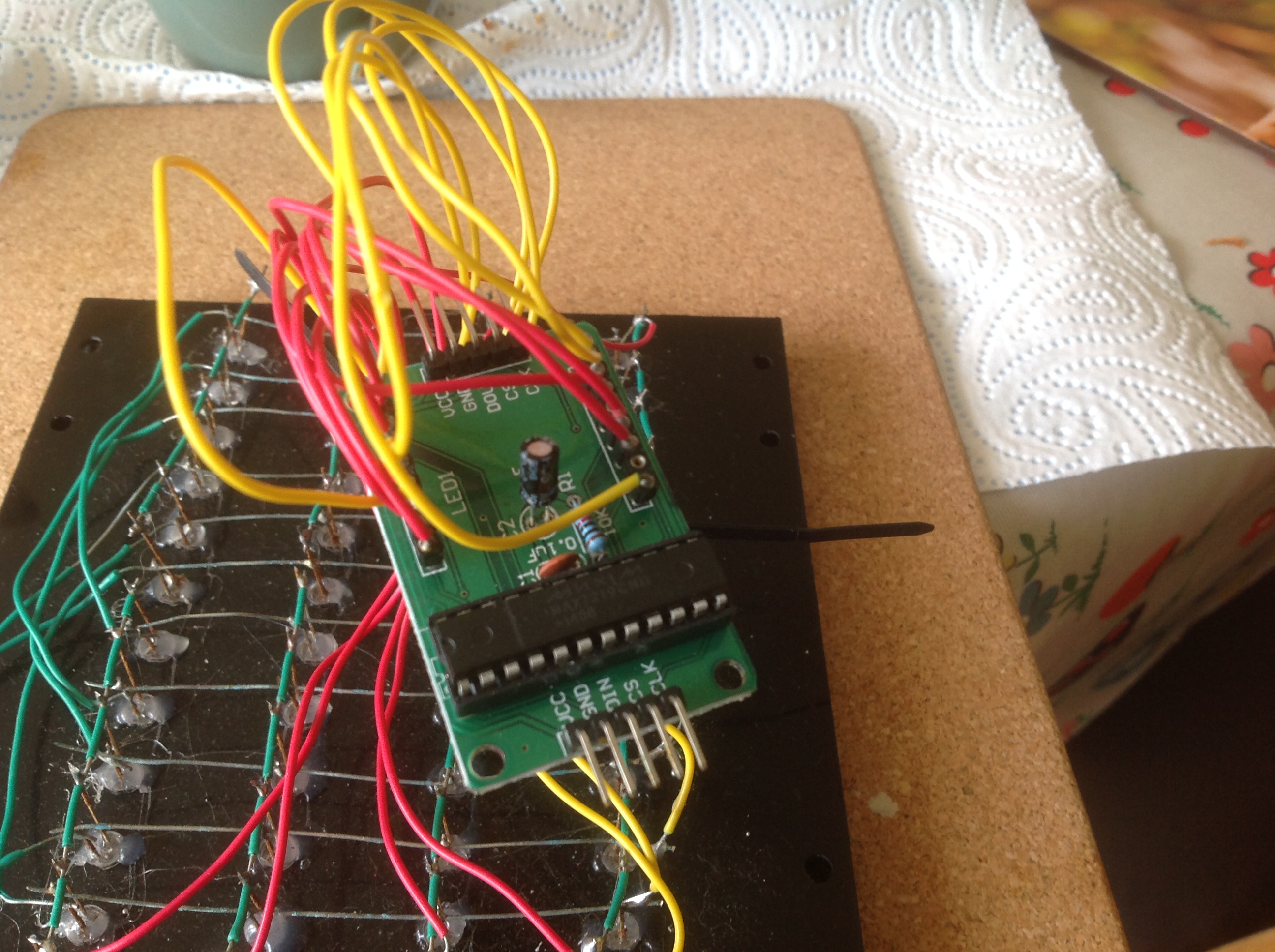
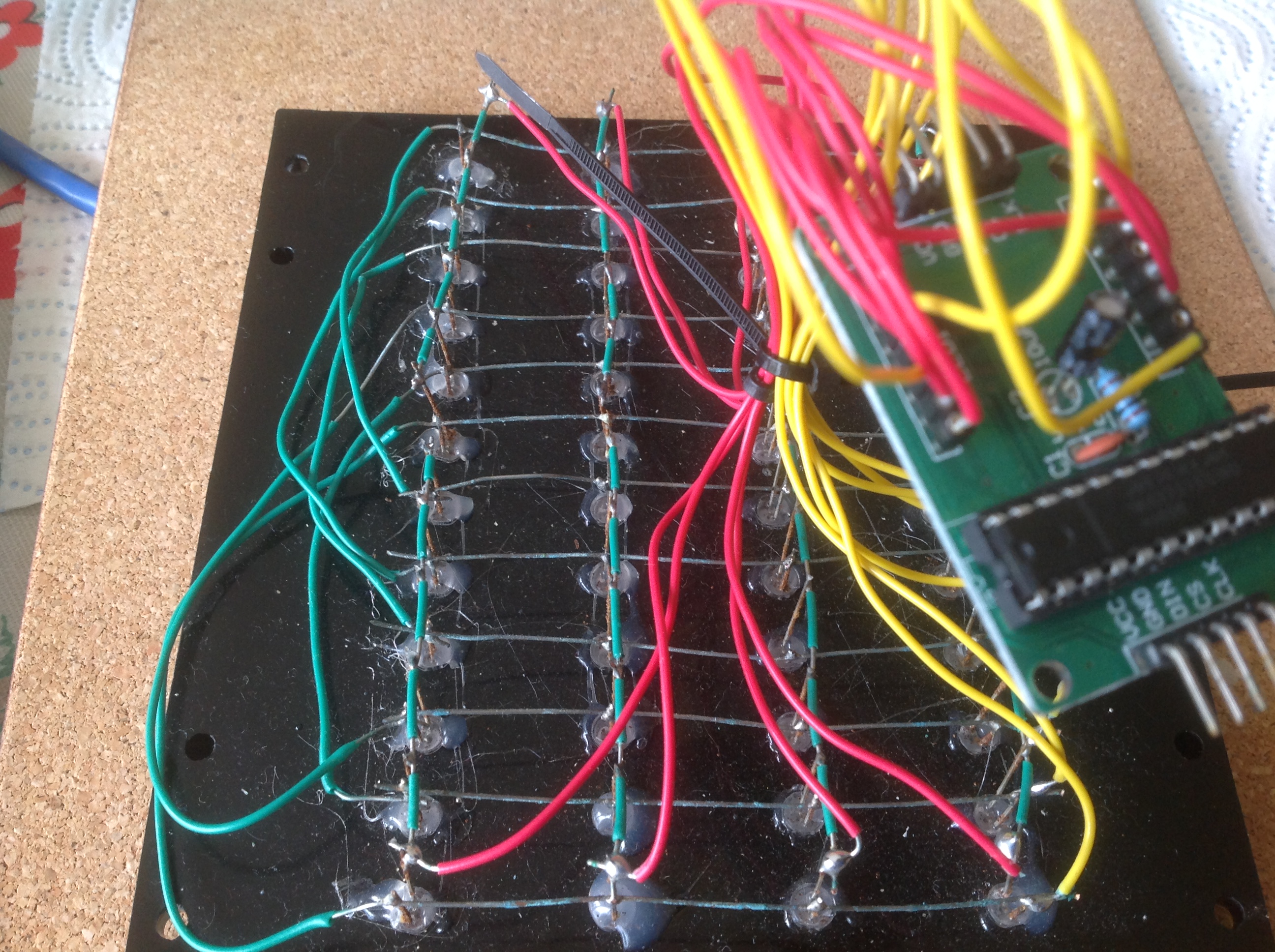
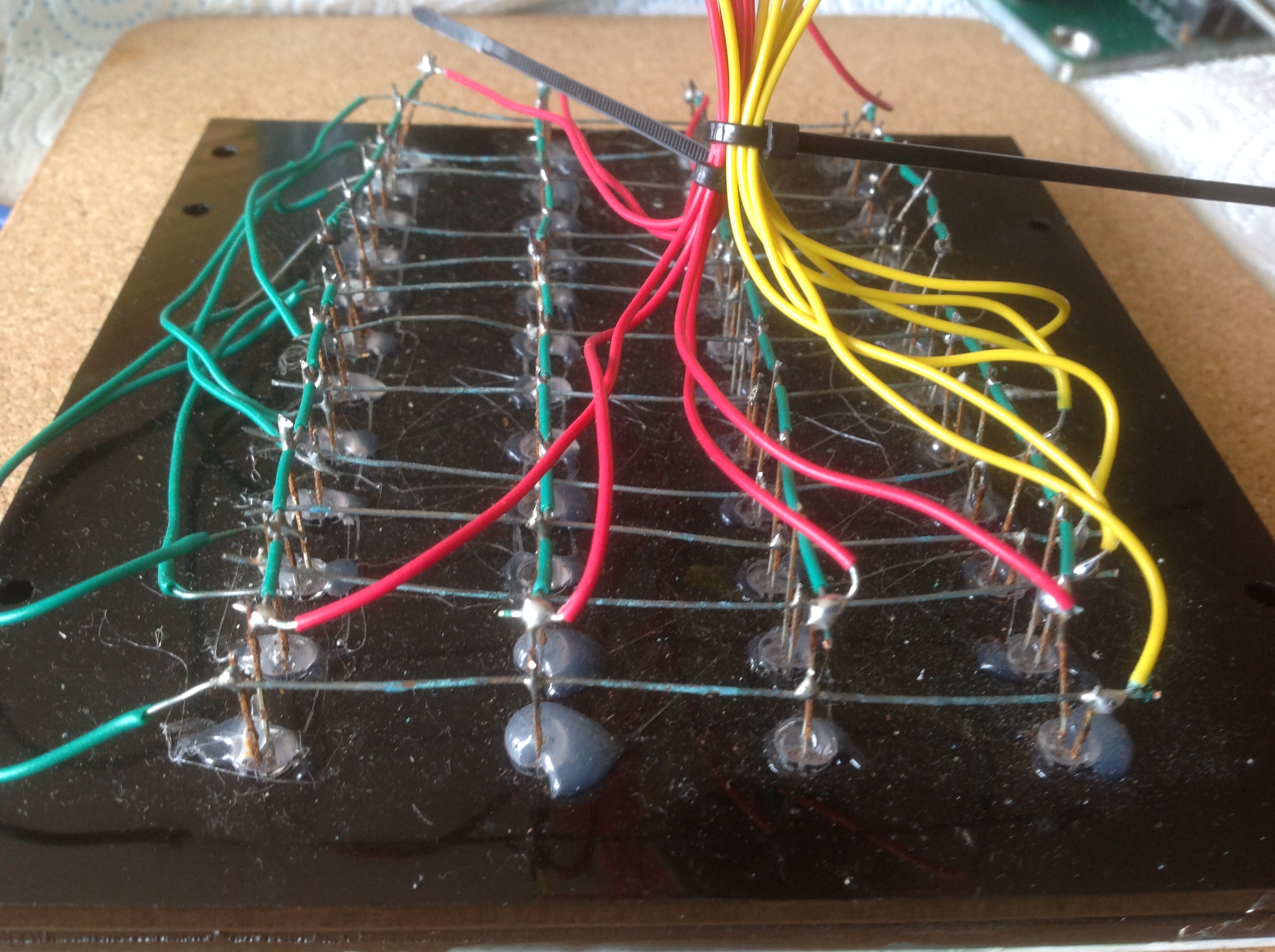
Hi please see the pictures attached. The 7219 chip is one of the modules you can buy from China, which comes in kit form; I soldered it myself so not pre-assembled. The matrix follows tigershark schematic and I have soldered a common wire between Anode and Cathode wires on each LED. I have done this in two blocks with a linking wire. With hindsite I would have used 2 led for each indicator and when I have completed all my panels I may revisit this one and use two leds. Thanks for your help. Neal
-
Hi its the Led itself that is lighting up, but probably about a quarter of the normal brightness!
-
Almost there Hi Ian thanks for the reply, that clarified everything. I managed to get the panel connected and working, albeit with the columns reversed. A quick alteration to the sketch and all the correct LEDs work - Hooray, pleased as punch! One thing that I have noticed is that I get some of the non active (that is not lit on the caution panel in the Sim) flashing or coming on, but very very dim. Can anyone advise what might be causing this? I am not sure if its hardware or software related. Success in increments is still success! Thanks Neal
-
Next step Hi I solved the above issue by loading the LED Control library; thank you. The sketch loaded ok onto my Uno and I connected to DCS world, ran the Cmd window and ran DCS world - Nothing fundamental happened in that no caution lights came on. I then reread 'http://forums.eagle.ru/showthread.ph...highlight=clay and realised that I had not set the mapping correctly; Now done. However when studying the sketch my poor brain could not understand: //pin 10 is connected to the DataIn //pin 11 is connected to the CLK //pin 12 is connected to LOAD LedControl lc=LedControl(2,4,3,1);//DIN,CLK,LOAD,# OF IC's I am I correct in assuming that in the above example DIN is connected to Pin 2, CLK to Pin 4, Load to pin 3? I am not sure what # of IC's means and if that should then connect to Pin 1? Sorry if this seems like a dense question. Thanks Neal
-
Hi I am exploring options at the moment, one which I am looking at is a bit of a blunt instrument; I am installing an LED flat panel inside my side panel structure, effectively turning the whole lot into a big internally lit box. I will then have various 'slots' cut in the facing material (plastic cardboard, with duct tape seams). The UFC I am installing a series of 5050 LEDs. All the back lighting will be connected to the main electrical panel 'Power switch' using a double pole switch. It all sound good in theory, but maybe a horses arse of an idea in reality! Great fun experimenting. Neal
-
Hi After many months of contemplation I have finally started my panels. I have started with my UFC and Caution panel. The faceplates are made on a laser cutter using 1.5mm laserable laminate with a black face and a white back layer. These are then mounted on a 3mm green acrylic. I have used the highly technical method of hot glue to fix all of my switches. All of my switches, pots, encoders etc are all sources over many weeks from china, using multiple suppliers. I am using the fabulous DCS Bios, which is so far very simple and intuitive. I have purchased a teach your self how to programme Arduino so that I can have half a chance of understanding the rudiments of programming. I will post more as I work on them. Best wishes Neal
-
Hi I am having an issue with loading the DCS Bios sketch for my recently constructed Caution light panel. The panel is wired in a matrix based on tigershark thread. The code is: #define DCSBIOS_IRQ_SERIAL #include <DcsBios.h> #include <LedControl.h> //pin 10 is connected to the DataIn //pin 11 is connected to the CLK //pin 12 is connected to LOAD LedControl lc=LedControl(2,4,3,1);//DIN,CLK,LOAD,# OF IC's unsigned char cl_row_map[48] = { 5, 5, 1, 1, 5, 5, 1, 1, 5, 5, 1, 1, 3, 3, 7, 7, 3, 3, 7, 7, 3, 3, 7, 7, 6, 6, 2, 2, 6, 6, 2, 2, 6, 6, 2, 2, 0, 0, 4, 4, 0, 0, 4, 4, 0, 0, 4, 4, }; #define SEG_DP (1<<7) #define SEG_A (1<<6) #define SEG_B (1<<5) #define SEG_C (1<<4) #define SEG_D (1<<3) #define SEG_E (1<<2) #define SEG_F (1<<1) #define SEG_G (1<<0) unsigned char cl_mask_map[48]= { SEG_B, SEG_G, SEG_G, SEG_B, SEG_C, SEG_E, SEG_E, SEG_C, SEG_DP, SEG_D, SEG_D, SEG_DP, SEG_B, SEG_G, SEG_G, SEG_B, SEG_C, SEG_E, SEG_E, SEG_C, SEG_DP, SEG_D, SEG_D, SEG_DP, SEG_B, SEG_G, SEG_G, SEG_B, SEG_C, SEG_E, SEG_E, SEG_C, SEG_DP, SEG_D, SEG_D, SEG_DP, SEG_B, SEG_G, SEG_G, SEG_B, SEG_C, SEG_E, SEG_E, SEG_C, SEG_DP, SEG_D, SEG_D, SEG_DP, }; unsigned char max7219_rows[8]; void setup() { DcsBios::setup(); memset(max7219_rows, 0xff, sizeof(max7219_rows)); lc.shutdown(0,false); //turn on the display lc.setIntensity(0,8);//set the brightness lc.clearDisplay(0); //clear rthe display and get ready for new data } void updateCautionLights(unsigned int address, unsigned int data) { unsigned char clp_row = (address - 0x10d4) * 2; unsigned char start_index = clp_row * 4; unsigned char column = 0; unsigned char i; bool is_on; for (i=0; i<16; i++) { is_on = data & 0x01; // set caution light state (clp_row, column, is_on) if (is_on) { max7219_rows[cl_row_map[start_index+i]] |= cl_mask_map[start_index+i]; } else { max7219_rows[cl_row_map[start_index+i]] &= ~(cl_mask_map[start_index+i]); } data >>= 1; column++; if (column == 4) { clp_row++; column = 0; } } } void onClpData1Change(unsigned int newValue) { updateCautionLights(0x10d4, newValue); } DcsBios::IntegerBuffer clpData1(0x10d4, 0xffff, 0, onClpData1Change); void onClpData2Change(unsigned int newValue) { updateCautionLights(0x10d6, newValue); } DcsBios::IntegerBuffer clpData2(0x10d6, 0xffff, 0, onClpData2Change); void onClpData3Change(unsigned int newValue) { updateCautionLights(0x10d8, newValue); } DcsBios::IntegerBuffer clpData3(0x10d8, 0xffff, 0, onClpData3Change); void loop() { DcsBios::loop(); // update MAX7219 unsigned char i; for (i=0; i<8; i++) { lc.setRow(0, i, max7219_rows[i]); } } I get an error message: C:\Users\baker_000\Documents\Arduino\Caution_panel\Caution_panel.ino:3:24: fatal error: LedControl.h: No such file or directory #include <LedControl.h> ^ compilation terminated. exit status 1 Error compiling. Can anyone advise on this error? Thanks Neal
-
Hi I took my plans into a local school and had them cut on a laser cutter, and I made a donation to their current fundraising. The compromise was that the max thickness of ply it would cut was 9mm. This actually worked fine as long as you use interior ply. I think it cost £60 in wood and £150 donation. Neal
-
Hi Warhog sorry to hear you have been unwell, I hope things improve! On a cheeky note considering its not your own thread, would you be happy to share your updated details for your caution panel? I have previously used your older design but messed up the LED matrix a bit and am just starting to redo the panel; chinese parts pending? Regards Neal
-
Flight Qualifications Campaign
0414 Wee Neal replied to Sabre-TLA's topic in A-10C Basic Flight Training Qualification DLC
Skip practice mission Hi how can i skip a practice mission on the DLC version please, its BFT01? Great campaign by the way! Neal