0414 Wee Neal
-
Posts
338 -
Joined
-
Last visited
Content Type
Profiles
Forums
Events
Everything posted by 0414 Wee Neal
-
Hi I have just finished my Landing gear panel and connected all switches and LEDs to an Arduino Nano. When I was testing the panel in the Cmd window all switches work and register; all good so far. I started DCS World and A10C module and all switches work fine, however the LEDs keep flickering. I have set these up with 2 Green LEDs per landing wheel, so that I have a total of 6 LED connected. Can anyway assist in identifying the problem? I suspect it may be that the NANO cannot run 6 LED from the USB connection? Thanks Neal
-
Hi NickD there are a few ways of doing it and its worth trawling through some of the great threads, which show the different ways. Personally I use a clear acrylic back panel, the acrylic is a 'light guide panel' taken from a 600mmx600mm LED flat panel, which is then cut to size using a laser cutter. The front plate is made from laser engravable laminate, I use 1.5mm thick white with a black face. This then also laser cut and etched. See my post https://forums.eagle.ru/showthread.php?t=166687 I am very Happy to answer any questions you may have? There are a great many very helpful Simmers who have lots of posts, but be prepared for allot of reading. You may want to start with this thread: https://forums.eagle.ru/showthread.php?p=2356934 Regards Neal
-
Hi for anyones interested, I came across A10c panels for sale: http://hispapanels.com/tienda/en/80-a-10-thunderbolt-ii I have no interest in this company, only use them to buy the odd bit. Regards Neal
-
Hi I am finalising my landing gear panel and have set up my sketch for the flaps servo, however my tired old brain is struggling to comprehend what the Min and Max pulse widths are. I have used the following: DcsBios::ServoOutput flapPos(0x10a0, 9, 1060, 150); from https://forums.eagle.ru/showthread.php?t=150183&page=2 These parameters work, in that the servo rotates correctly. My issue is that I have no idea why that should be so. Can anyone explain how the above numbers correlate to actual movement angles of the servo? I have read alot of forums and I am still none the wiser:helpsmilie: Thanks Neal
-
Hi [FSF]Ian great to hear that DCS Bios 2.0 is in the pipeline, do you have a view on likely timeframe? DCS Bios is superb thank you. Neal
-
AAAh sounds like British humour!;-}
-
Get on with it then:smilewink: Monies burning a hole!!
-
Hi, thanks for the reply. I have wired in RS485 modules for each Arduino, but because of the difficulties of updating sketches etc i.e. quoting out RS485 comment to allow usb connection and update as required. I think when DCS Bios is developed to the next stage I will then initialise network.:thumbup:

-
DCS BIOS - .Cmd question Good evening I am gradually improving my knowledge of DCS BIOS. I have built the majority of my panels with 7 of them fully wired and connected to a combination of Arduino Mega (1x), Arduino Uno (4x) and Arduino Nano (4x). I have compiled my sketches and downloaded to each Arduino, and have tested all panels - Success. I have now fitted my panels in my cockpit and connected them all to a powered Hub, I have then copied the 'connect-serial-port.cmd' once for each panel and renamed to match the panel, changing the port number as appropriate. The question I have is do I have to open all of the .cmd files (1 per panel) or is there a way of having a .cmd fie that will allow all to work. In a nutshell do I need to open a separate .cmd for all my panels, potentially 30 Ports? I hope that makes sense? Neal
-
Hi Gus my sketch for CMSP is: /* Tell DCS-BIOS to use a serial connection and use interrupt-driven communication. The main program will be interrupted to prioritize processing incoming data. This should work on any Arduino that has an ATMega328 controller (Uno, Pro Mini, many others). */ #define DCSBIOS_IRQ_SERIAL #include "DcsBios.h" #include <LiquidCrystal.h> LiquidCrystal lcd(12, 11, 5, 4, 3, 2); void onCmsp1Change(char* newValue) { lcd.setCursor(0,0); lcd.print(newValue); } DcsBios::StringBuffer<19> cmsp1Buffer(0x1000, onCmsp1Change); void onCmsp2Change(char* newValue) { lcd.setCursor(0,1); lcd.print(newValue); } DcsBios::StringBuffer<19> cmsp2Buffer(0x1014, onCmsp2Change); // set up the set button 1: DcsBios::Switch2Pos cmspArw1("CMSP_ARW1", 6); // set up the set button 2: DcsBios::Switch2Pos cmspArw2("CMSP_ARW2", 7); // set up the set button 3: DcsBios::Switch2Pos cmspArw3("CMSP_ARW3", 8); // set up the set button 4: DcsBios::Switch2Pos cmspArw4("CMSP_ARW4", 9); void setup() { DcsBios::setup(); // set up the LCD's number of columns and rows: lcd.begin(16, 2); // Print a message to the LCD. lcd.clear(); } void loop() { DcsBios::loop(); } would I insert your suggested changes in the void setup? Thanks Neal
-
Hi That would be great. I have also bought one of their VGA LCD screens for my CDU, although I have not made the faceplate yet. I agree the 20x2 is big, I have currently got a 16x2 working, which first pointed me to the fact I can't count; i forgot to factor in the spaces! I am trying to work up enthusiasm to re solder all of those damn wires!!! Neal
-
Hi I searched high and low for a 20x2 display and came across these: http://www.buydisplay.com/default/catalogsearch/result/?cat=&q=Arduino+20x2+LCD+Module+Display+ good price and fast delivery. Neal
-
Hi unfortunately this question is beyond my knowledge to answer, i suggest you post on the DCS BIOS discussion thread which i am sure will illicit a response from the clever people we have the benefit of. Sorry i cant help. Neal
-
Hi John on another note, what Servos are you using for flap, oxygen etc? Neal
-
Hi John excellent idea, certainly makes life easier. I have also noted that DCS Bios already has these set up in the reference documentation; happy days. Thanks for the reply. Neal
-
Hi Thanks for the reply, I will try that. Neal
-
Hi I have connected a Potentiometer to my VHF FM panel, which is set up: a. Arduino Nano - Based on IRQ Serial sketch b. Max 7219 module connected to a 6 digit 7 segment display c. I have connected the Max7219 modue and the 4 rotary encoders to a Nano which has a RS485 module connected but not coded as yet. d. I have connected 1x 3 pos switch for Squelch e. I have connected 1 x Pot for the volume, connected to the A0 pin. The Pot does not seem to operate the vol control effectively. The problem I have is that the Pot is sending a steady stream of readings and only stops when I turn it fully to the left when the reading is then 0. I have made an assumption that this is due to fluctuating readings from the Pot itself. I have coded a 'smoothing' element to my sketch to try and stop this happening: #define DCSBIOS_IRQ_SERIAL #include "DcsBios.h" /*/ Define the number of samples to keep track of. The higher the number, // the more the readings will be smoothed, but the slower the output will // respond to the input. Using a constant rather than a normal variable lets // use this value to determine the size of the readings array. */ const int numReadings = 700; int readings[numReadings]; // the readings from the analog input int readIndex = 0; // the index of the current reading int total = 0; // the running total int average = 0; // the average int inputPin = A0; /* paste code snippets from the reference documentation here */ DcsBios::Potentiometer vhffmVol("VHFFM_VOL", A0); void setup() { DcsBios::setup(); // initialize serial communication with computer: /* Serial.begin(9600); */ // initialize all the readings to 0: for (int thisReading = 0; thisReading < numReadings; thisReading++) { readings[thisReading] = 0; } } void loop() { DcsBios::loop(); // subtract the last reading: total = total - readings[readIndex]; // read from the sensor: readings[readIndex] = analogRead(inputPin); // add the reading to the total: total = total + readings[readIndex]; // advance to the next position in the array: readIndex = readIndex + 1; // if we're at the end of the array... if (readIndex >= numReadings) { // ...wrap around to the beginning: readIndex = 0; } // calculate the average: average = total / numReadings; // send it to the computer as ASCII digits /* Serial.println(average); delay(1); // delay in between reads for stability*/ } This has slowed the data being received but in no way stopped it. I have a few questions: 1. I have tried 2 other pots and they have the same effect - Is his normal? 2. Am I using the wrong pots - 10k rated? 3. Help! Many thanks in advance. Neal
-
Hi Its a great sense of achievement when it works! I solved the DP matter, which is simply a case of changing false to true on the relevant digit. An important observation is that with my 6 digit display and 7219 module I could only wire in 1 DP. Neal
-
Hi John I had to play around with some of the digit position numbers but it works like a dream, except the DP does not display. When first started the DP illuminates so I know that it works. My sketch so far: /* Tell DCS-BIOS to use a serial connection and use interrupt-driven communication. The main program will be interrupted to prioritize processing incoming data. This should work on any Arduino that has an ATMega328 controller (Uno, Pro Mini, many others). */ #define DCSBIOS_IRQ_SERIAL #include <DcsBios.h> #include <SegmentDisplay.h> #include <LedControl.h> //pin 3 is connected to the DataIn //pin 5 is connected to the CLK //pin 4 is connected to LOAD LedControl lc=LedControl(3,5,4,1); //This creates an instance of a single controller named "lc" /* The sequence of pins used above are in the following order... LedControl(DIN,CLK,LOAD,# OF IC's) pin 3 is connected to the DataIn pin 5 is connected to the CLK pin 4 is connected to LOAD the last number...(1) is for how many MAX7219 we have daisy chained. */ void onVhfamFreq1Change(char* newValue) { lc.setChar(0,1,newValue[0],false); lc.setChar(0,2,newValue[1],true); } DcsBios::StringBuffer<2> vhfamFreq1StrBuffer(0x1190, onVhfamFreq1Change); void onVhfamFreq2Change(unsigned int newValue) { lc.setChar(0,3,newValue,false); } DcsBios::IntegerBuffer vhfamFreq2Buffer(0x118e, 0x00f0, 4, onVhfamFreq2Change); void onVhfamFreq3Change(unsigned int newValue) { lc.setChar(0,4,newValue,false); } DcsBios::IntegerBuffer vhfamFreq3Buffer(0x118e, 0x0f00, 8, onVhfamFreq3Change); void onVhfamFreq4Change(char* newValue) { lc.setChar(0,5,newValue[0],false); lc.setChar(0,6,newValue[1],false); } DcsBios::StringBuffer<2> vhfamFreq4StrBuffer(0x1192, onVhfamFreq4Change); void setup() { DcsBios::setup(); //This initializes the MAX7219 and gets it ready of use: lc.shutdown(0,false); //turn on the display lc.setIntensity(0,8);//set the brightness lc.clearDisplay(0); //clear the display //The following series of "lc.setChar" commands are used to display the number 8 in each digit. This allows us to see each that LED segment is actually working. lc.setChar(0,0,'8',false);// The first number...0, means there are no other MAX7219's connected to the one we are using. lc.setChar(0,1,'8',false);// The second number...1, indicates the digit you are sending data too...digit numbering starts at 0. lc.setChar(0,2,'8',true);// The third number in single quotes is the character thats displayed lc.setChar(0,3,'8',false);// The statement... true/false is to turn on or off the decimal point (dp) for that particular digit. lc.setChar(0,4,'8',false); lc.setChar(0,5,'8',false); } void loop() { DcsBios::loop(); } Neal
-
Hi I have been working on a sketch (fro Warhog) for my vhf am radio and so far it all works well; except I cannot seem to get the decimal point to show. I am using a Nano connected to a MAX7219 module, which has a 6 digit 7 segment display attached. The sketch: /* Tell DCS-BIOS to use a serial connection and use interrupt-driven communication. The main program will be interrupted to prioritize processing incoming data. This should work on any Arduino that has an ATMega328 controller (Uno, Pro Mini, many others). */ #define DCSBIOS_IRQ_SERIAL #include <DcsBios.h> #include <SegmentDisplay.h> #include <LedControl.h> //pin 3 is connected to the DataIn //pin 5 is connected to the CLK //pin 4 is connected to LOAD LedControl lc=LedControl(3,5,4,1); //This creates an instance of a single controller named "lc" /* The sequence of pins used above are in the following order... LedControl(DIN,CLK,LOAD,# OF IC's) pin 3 is connected to the DataIn pin 5 is connected to the CLK pin 4 is connected to LOAD the last number...(1) is for how many MAX7219 we have daisy chained. */ void onVhfamFreq1Change(char* newValue) { lc.setChar(0,1,newValue[0],false); lc.setChar(0,2,newValue[1],true); } DcsBios::StringBuffer<2> vhfamFreq1StrBuffer(0x1190, onVhfamFreq1Change); void onVhfamFreq2Change(unsigned int newValue) { lc.setChar(0,3,newValue,false); } DcsBios::IntegerBuffer vhfamFreq2Buffer(0x118e, 0x00f0, 4, onVhfamFreq2Change); void onVhfamFreq3Change(unsigned int newValue) { lc.setChar(0,4,newValue,false); } DcsBios::IntegerBuffer vhfamFreq3Buffer(0x118e, 0x0f00, 8, onVhfamFreq3Change); void onVhfamFreq4Change(char* newValue) { lc.setChar(0,5,newValue[0],false); lc.setChar(0,6,newValue[1],false); } DcsBios::StringBuffer<2> vhfamFreq4StrBuffer(0x1192, onVhfamFreq4Change); void setup() { DcsBios::setup(); //This initializes the MAX7219 and gets it ready of use: lc.shutdown(0,false); //turn on the display lc.setIntensity(0,8);//set the brightness lc.clearDisplay(0); //clear the display //The following series of "lc.setChar" commands are used to display the number 8 in each digit. This allows us to see each that LED segment is actually working. lc.setChar(0,0,'8',false);// The first number...0, means there are no other MAX7219's connected to the one we are using. lc.setChar(0,1,'8',false);// The second number...1, indicates the digit you are sending data too...digit numbering starts at 0. lc.setChar(0,2,'8',true);// The third number in single quotes is the character thats displayed lc.setChar(0,3,'8',false);// The statement... true/false is to turn on or off the decimal point (dp) for that particular digit. lc.setChar(0,4,'8',false); lc.setChar(0,5,'8',false); } void loop() { DcsBios::loop(); } When the Nano is first connected all of the digits and the 3rd DP illuminate. When connecting to the .Cmd and DCS Warthog the radio frequency displays no problem, except the DP. can anyone advise on what may be wrong? Thanks Neal
-
What switches - Intercom Control panel
0414 Wee Neal replied to 0414 Wee Neal's topic in Home Cockpits
Thanks Thankyou for the advice, much appreciated. Neal -
Hi I am just starting to finalise the details for my latest panel - Intercom Panel, but I cannot seem to find a switch which fits the bill. As I understand the manual they are push button on/off which you also use as a volume control. Can anyone advise on how they have dealt with these switches please? In the manual they are numbered buttons/switches 2 to 9. Thanks Neal
-
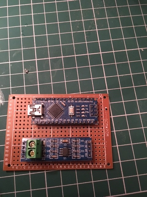
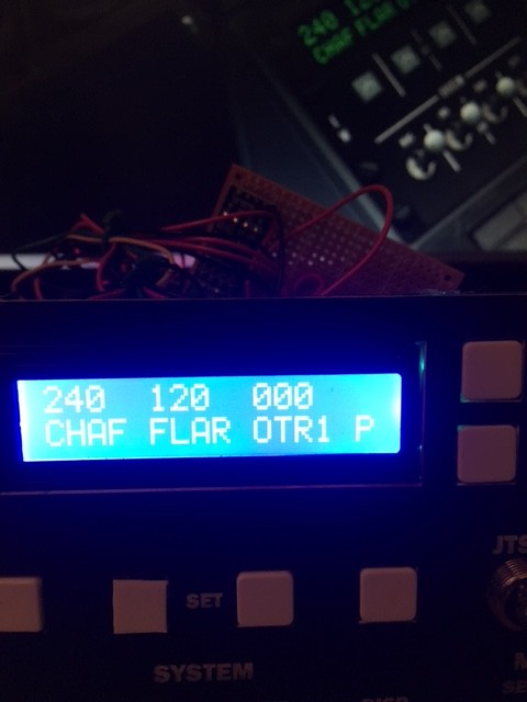
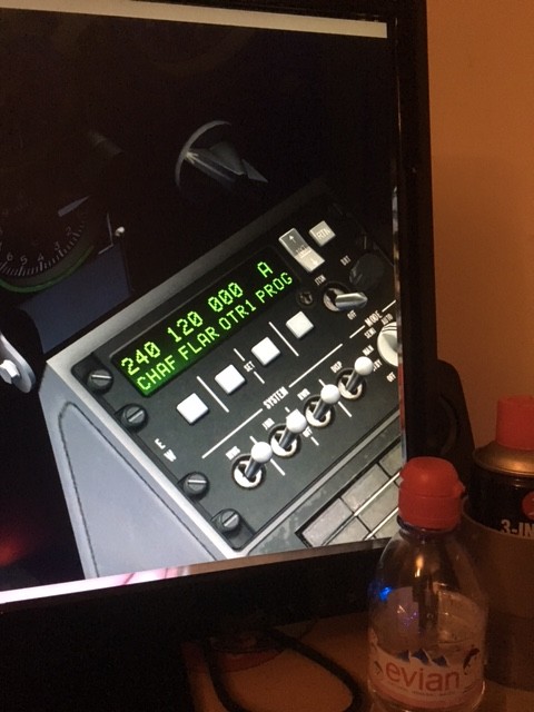
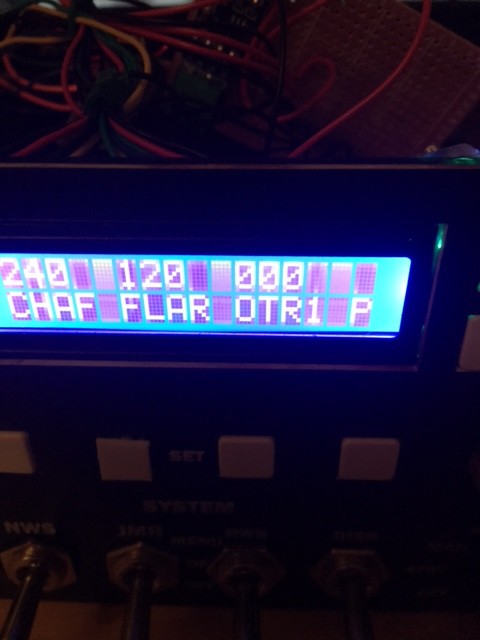
DCS Bios - CMSP LCD issues Hi I have compiled my sketch for my CMSP and it works; mostly! I have a Nano connected to a 16 x 2 lcd Shield. I have directly wired the Pot to the shield rather than through the sketch (for contrast). When i run Cmd and DCS A10c the display characters extend beyond the 16 character spaces, see picture. You can see on the 2nd line the last word should be PROG and all we see is P, there is no space for ROG. My sketch is below: /* Tell DCS-BIOS to use a serial connection and use interrupt-driven communication. The main program will be interrupted to prioritize processing incoming data. This should work on any Arduino that has an ATMega328 controller (Uno, Pro Mini, many others). */ #define DCSBIOS_IRQ_SERIAL #include "DcsBios.h" #include <LiquidCrystal.h> LiquidCrystal lcd(12, 11, 5, 4, 3, 2); void onCmsp1Change(char* newValue) { lcd.setCursor(0,0); lcd.print(newValue); } DcsBios::StringBuffer<19> cmsp1Buffer(0x1000, onCmsp1Change); void onCmsp2Change(char* newValue) { lcd.setCursor(0,1); lcd.print(newValue); } DcsBios::StringBuffer<19> cmsp2Buffer(0x1014, onCmsp2Change); // set up the set button 1: DcsBios::Switch2Pos cmspArw1("CMSP_ARW1", 6); // set up the set button 2: DcsBios::Switch2Pos cmspArw2("CMSP_ARW2", 7); // set up the set button 3: DcsBios::Switch2Pos cmspArw3("CMSP_ARW3", 8); // set up the set button 4: DcsBios::Switch2Pos cmspArw4("CMSP_ARW4", 9); void setup() { DcsBios::setup(); // set up the LCD's number of columns and rows: lcd.begin(16, 2); // Print a message to the LCD. lcd.clear(); } void loop() { DcsBios::loop(); } Have i missed something in the sketch? Any advise would be gratefully received. Thanks Neal
-
Hi Ian thank you for the response, I appreciate the time you take as some of the questions I ask must seem very basic! Still if you are ever building a house I could maybe reciprocate! Neal
-
Hi Ian would something like this work? http://www.titino.eu/ Neal