hegykc
-
Posts
791 -
Joined
-
Last visited
-
Days Won
4
Content Type
Profiles
Forums
Events
Everything posted by hegykc
-
KG13 is my personal favorite, so you better believe it.
-
Haha sorry, all of these guys is just me :)
-
Still work to do there but yes. You mean something like this? :music_whistling:
-
I wouldn't put a direct contact friction gimbal on a 15$ piece of crap if you ask me. So yes, real gimbal with roller bearings, fully adjustable and separate forces for pitch and roll and oil dampers. Yes, including all the hats, buttons and switches. Everything will be available as a separate buy, for anyone interested in making their own hotas. M36x2 but google that to make sure, I just have it modeled, but forgot. Yes. Everything is designed "Lego" style. Pick the parts you want and put them together. The grip alone, yes. The base would be another purchase. My goal is for the whole set (grip+base and throttles+base) to be below the price range of the warthog.
-
No, not if you can wait. I have the prototype base designed. Electronics and firmware are in testing phase. I will start prototyping the base once I have a functional grip.
-
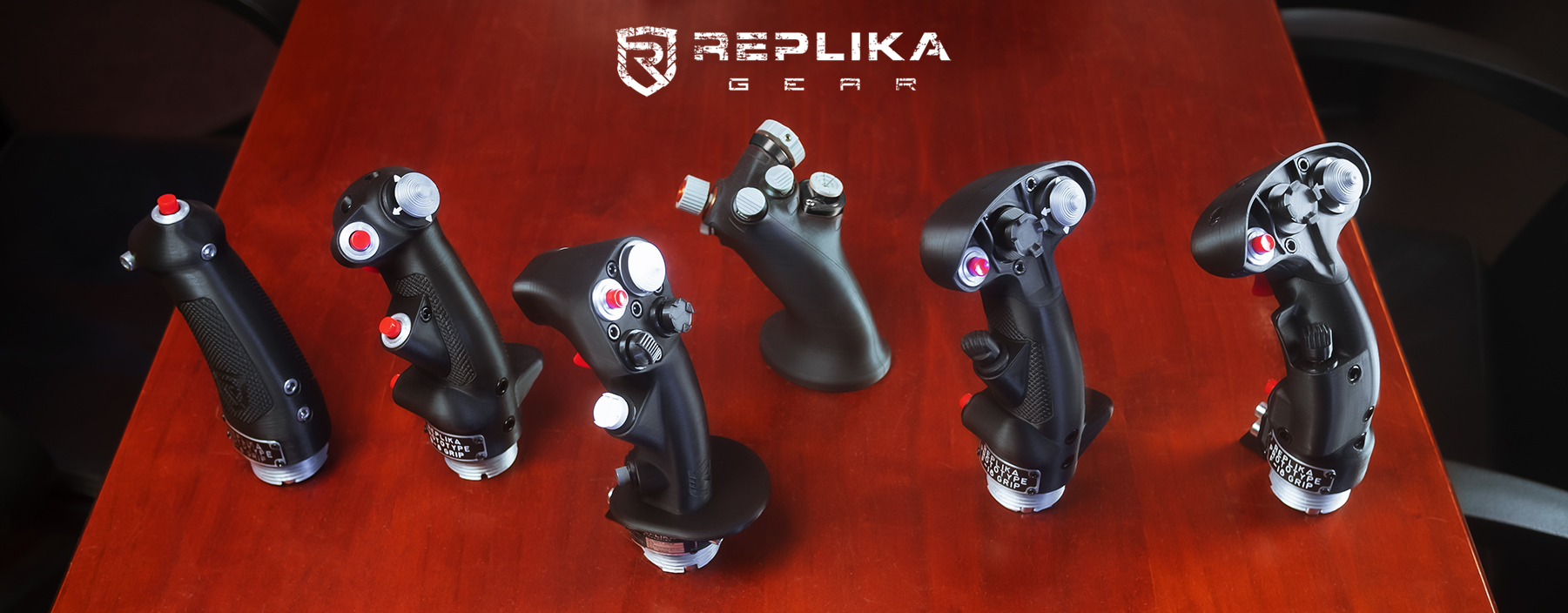
It is a combination of solidworks, 3ds max and photoshop. A good render is never "push a button" kind of thing. Takes quite a bit of tweaking for each scene. The one seen here took me about 3 hours just to setup the scene for rendering. I will be making slew control replacements as soon as I calibrate the printer and try different materials. I don't do waiting lists. Hate them. This will not be a "one off" run. I have laid the groundwork for the production of thousands per month if needed, or just a couple each day if that will be the case. I will setup my work shop acording to the demand. There will my own base for these grips, much better then the warthog one. Update: I spent the cheap printer material I had for testing purpposes. Have to wait for the good stuff to arrive this friday, or next week.
-
Everything is a prototype at this point, including the threaded nuts. Design a logo and come up with a name, check and check!
-

Broken wire's on Warthog throttle front hat switch
hegykc replied to RangerUK's topic in PC Hardware and Related Software
You got it. Enjoy :pilotfly: -
Broken wire's on Warthog throttle front hat switch
hegykc replied to RangerUK's topic in PC Hardware and Related Software
This is looking from the left side of the right throttle: red wire goes to the left side of the hat, brown goes to the bottom. Or, red is 9 o'clock, brown is 7. -
We are officially into prototyping phase! Testing and calibrating the machine with "warthog-base connecting nuts": All the electronics and hardware for making completely functional prototypes have been ordered so it's getting real close to "two weeks" now :) Will post pictures of the complete grip in a couple of days. Took me 3 days just to set up the damn thing. And some other stuff that's in the works:
-
Slew switch is like a mouse, it moves in a 2D plane with +/- 2mm lateral movement, so making a longer shaft won't do any good. It is also has a "brain" that does it's own calculations, so replacing it with a simple mini joystick is also not an option. It has to be quite a complex little mechanism that will translate the "mouse 2D" movement into "joystick-like 3D" movement. It's coming after the grips go into functional prototype stage.
-
Saitek X55 grip-to-base connection
hegykc replied to hegykc's topic in PC Hardware and Related Software
They just couldn't go with regular pins.. great. Well, found those too, now just need the pin diameter and thread size. -
Hopefully the last update without pictures of actual prototypes. Looks like I will have to ask the admins to change the thread title to "... warthog AND X-55 compatible"
-
Hello x55 users. I have finally gotten do making my F-18 grip project X55 compatible also. On the electronics side, everything is cleared up, I would just like to ask for some info before I go out and buy one these for testing: 1) Can anyone identify the thread size that connects the grip to the base. 2) Size/diameter of the male pins on the grip. Are they just regular pins that stay in place, or they get pushed in by the plates on the base. I cannot see clearly on the pictures available
-
Warthog slew control replacement part
hegykc replied to hegykc's topic in PC Hardware and Related Software
Alright, so I found a bunch of these I2C mini joysticks. They're all 2d and have lateral movement, so it'll take a mechanism to convert that into 3d "joystick like" motion + center click. Doable, but it'll take a bit more time for me to design this. But it'll get done for sure, my warthog compatible F-18 throttle grips also need it. -
Warthog slew control replacement part
hegykc replied to hegykc's topic in PC Hardware and Related Software
Damn, so it has a second I²C for the slew itself. That's why there's 7 wires going out of that throttle grip, instead of only 5 if it were just the I²C for the digital button inputs? It's some off the shelf 2-axis with center push unit. I have to do some more research. I could use my design if there was a shift register that takes both digital and analog inputs, then I would just design a mini pcb for my slew design. -
Warthog slew control replacement part
hegykc replied to hegykc's topic in PC Hardware and Related Software
Correct, the right throttle grip has 2 shift registers. The left grip on the other hand has a button and a toggle that go straight to the main board in the throttle base. -
TM Hog Switch Replacement
hegykc replied to AurelTristen's topic in PC Hardware and Related Software
No problem. Here's the one you need to repair one of the buttons with the housing, like the paddle switch: http://www.ebay.com/itm/50pcs-Tact-Switch-SMT-SMD-Tactile-membrane-switch-PUSH-Button-SPST-NO-4x4x0-8mm-/181442700440?pt=LH_DefaultDomain_0&hash=item2a3ed3e498 and the 1.25mm pitch 2pin JST connector again. 2$ to repair 50 warthogs :) Although these ones are 4x4mm and the one in the warthog is 9.5x9.5mm but it should work. Anyway it's more likely that it's a bad solder as it seems, so check that first. -
TM Hog Switch Replacement
hegykc replied to AurelTristen's topic in PC Hardware and Related Software
All of the other buttons have a housing that snaps into the grip shell. I haven't looked for these, but I'm sure these "on the pcb tactile" switches can also be found on online retailers: -
TM Hog Switch Replacement
hegykc replied to AurelTristen's topic in PC Hardware and Related Software
The trigger is just a regular 12x12 mm tactile switch, they can be found anywhere. They're "through hole" connection, with the soldered wires and the leads bent back so the button slides in the grip housing. For a DIY repair you would need these from ebay. These are packs of 10, if you have access to Mouser or Digikey you might get away with ordering just one of each: 12mm tactile switch: http://www.ebay.com/itm/12mm-Tactile-Push-Button-Switch-Pack-of-10-/141117628292?pt=UK_BOI_Electrical_Components_Supplies_ET&hash=item20db441f84 And a 1.25mm pitch JST 2pin connector: http://www.ebay.com/itm/Micro-Mini-JST-Connector-1-25mm-2-pin-w-Wire-x-10-sets-/161344644655?pt=Radio_Control_Parts_Accessories&hash=item2590e3e62f -
There's been a few requests for a replacement slew control for the warthog. I am about to start making prototypes of my F-18 grip for the warthog base, so I will include this mini project along with it. Should be fairly straightforward and simple to both make and install. F-18 grip will still be a prototype, while these would be ready to go straight out of my industrial 3d printer, as they're small and not that essential plastic parts. Here is a render of the part assembly (in reality they would come with a pre-soldered 5pin cable): And the removal and installation process would look like this: 1)unscrew the three long screws 2)Unscrew the small one on the other side 3)unplug the 5pin slew connector 4)Push the plastic slew housing latch with a screwdriver 5)it pops right out 6-10) reverse the process for the installation of the replacement slew control . How would the joystick work, I don't know, it'll take some experimenting, maybe try a few different ones, we'll see. Comment or stay tuned for more. I start testing the week after next. EDIT: I mean, it'll work for sure, it's the same thing as the one inside, just with a full axis movement so the only question is will it feel much better then the cheap cellphone joystick they have in there now.
-
I have taken out the warthog slew, and will try to design my slew unit with the same diameter so it can fit into the warthog grip as a replacement part.There is a pcb inside the warthog throttle grip, and the slew connects to it with a 5pin connector, and both sides of the grip are removable plates, so slew replacement would actually be a super easy job.
-
Problem solved, thanks to Random. I will be starting printing the first prototypes this Monday, so finally some long overdue pictures are coming...
-
HELP Hi guys. I've been busy re-working the grip model from scratch. After closer examination some parts didn't match the real thing, so I completely re-did the entire model and the button and hat housings. Also the electronics are near finished. I had to learn pcb design so that took some time, there are several pcb's inside the grip, the main one plus one for each of the HAT's. Now, to my problem: I found my buttons and HAT's on Digikey and Mouser websites. The problem is, for my country they have a flat shipping rate, and it's 120.00$ which is insane, as I only need like 10 push buttons and 10 four way and five way switches for the HAT's to have a few prototypes made. After that I'll need a similar small order for the throttles. If there's anyone from EU that can receive shipments from Digikey and Mouser with a reasonable shipping rates, and then send the buttons in an envelope, back to me, here in Croatia, I would really appreciate the help. So someone from EU preferably, or US, it would still be cheaper than the 120$ option I have right now. This was something that went from being an off the shelf pushbutton, to an assembly with a custom pcb, housing and connector for a "no-solder" solution and a custom spring inside so I can decide on the actuation force myself. It delayed the project for a few more months, but now I have a professional and customizable solution, which I can also offer to other pitbuilders. These HATs often run about a 100$ a piece. I believe I can make these a sub 10$ part. So, anyone willing to help with the small order? I'd really appreciate it.
-
Get back on your horses gentlmen, this took a back seat to the F-18 grip and throttles project which is in the final stages now. It also needs some of the same technlology used for the grips, so I had to finish those first, then it's back to the instruments. Regarding the timeframe, if a multimilion dollar company haven't succeeded to make affordable ones in a decade, don't be surprised if it takes a guy in a garage a couple of years :)
