molevitch
-
Posts
532 -
Joined
-
Last visited
Content Type
Profiles
Forums
Events
Everything posted by molevitch
-
Razorback, hello again! I have been working on the switching for the autopilot system, and have been referring to a Mi-24/35 set of manuals put out in English, to try and better understand how they will work in the sim. Since I can only use them currently for the Mi-8 in DCS-BIOS I am basing my efforts on the Mi-8 autopilot, but anticipating the 24's AP also. Seeing that you have already produced the panels for the AP system. I want to ask how you will implement this system also. Regarding 3D printed pieces I mentioned in a post above, would you be willing to make a trade? As I mentioned before, I have a collective lever which I want to pass on.... Mole
-
Hey Razorback, What would you charge me for a set of those red/pink/orange fuse blocks? They look great! And also those nice little dashboard light posts. I could use a whole load of them. Mole
-
Yes, as the pilot’s feet are at the same height as the Gunner’s shoulders! But if I had a gunner who lived in my house and would join in regularly I would consider it.... Sadly my son has zero interest in flight sims proper. Though I do sometimes find him flying something in one of his own games. But not in a simulator way.
-
Looking great! I always wonder if I need a 3D printer, but I like doing things by hand.
-
I don’t have room for the gunners station. Or do I...?
-
Thank you Gentlemen! It’s a real labour of love and a massive learning adventure.
-
рычаги шасси Ми-24 Привет Mi8Pilot, У меня есть вопрос. Дайте мне, пожалуйста, техническую информацию о том, как работают рычаги шасси Ми-24. Я строю кабину Ми-24, и я не могу найти никаких диаграмм или видео этого. Спасибо. Mole
-
Thanks, that is nice to hear! :)
-
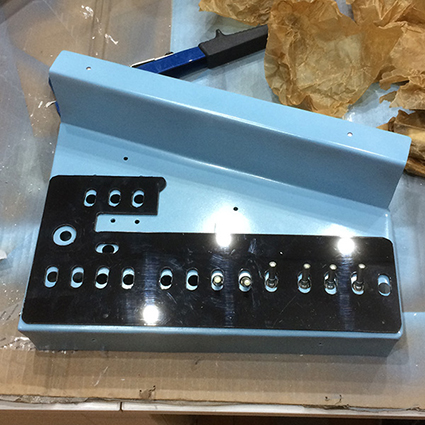
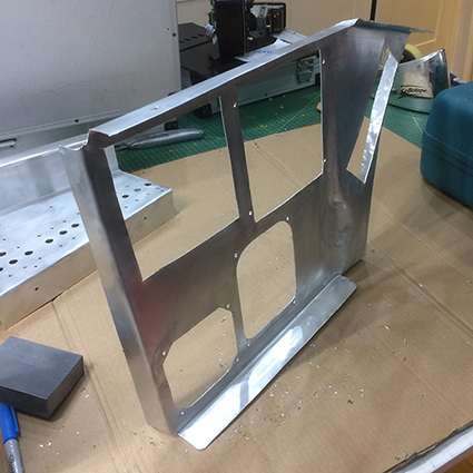
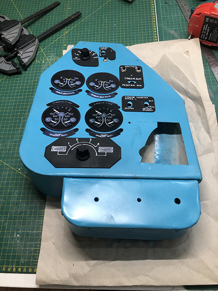
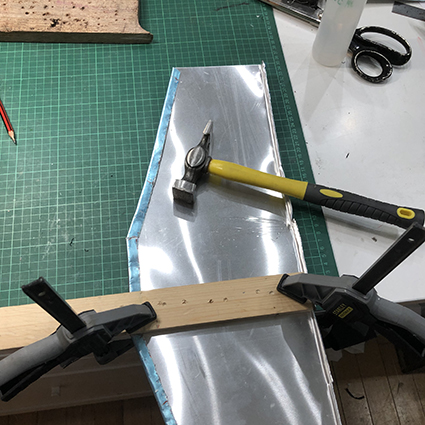
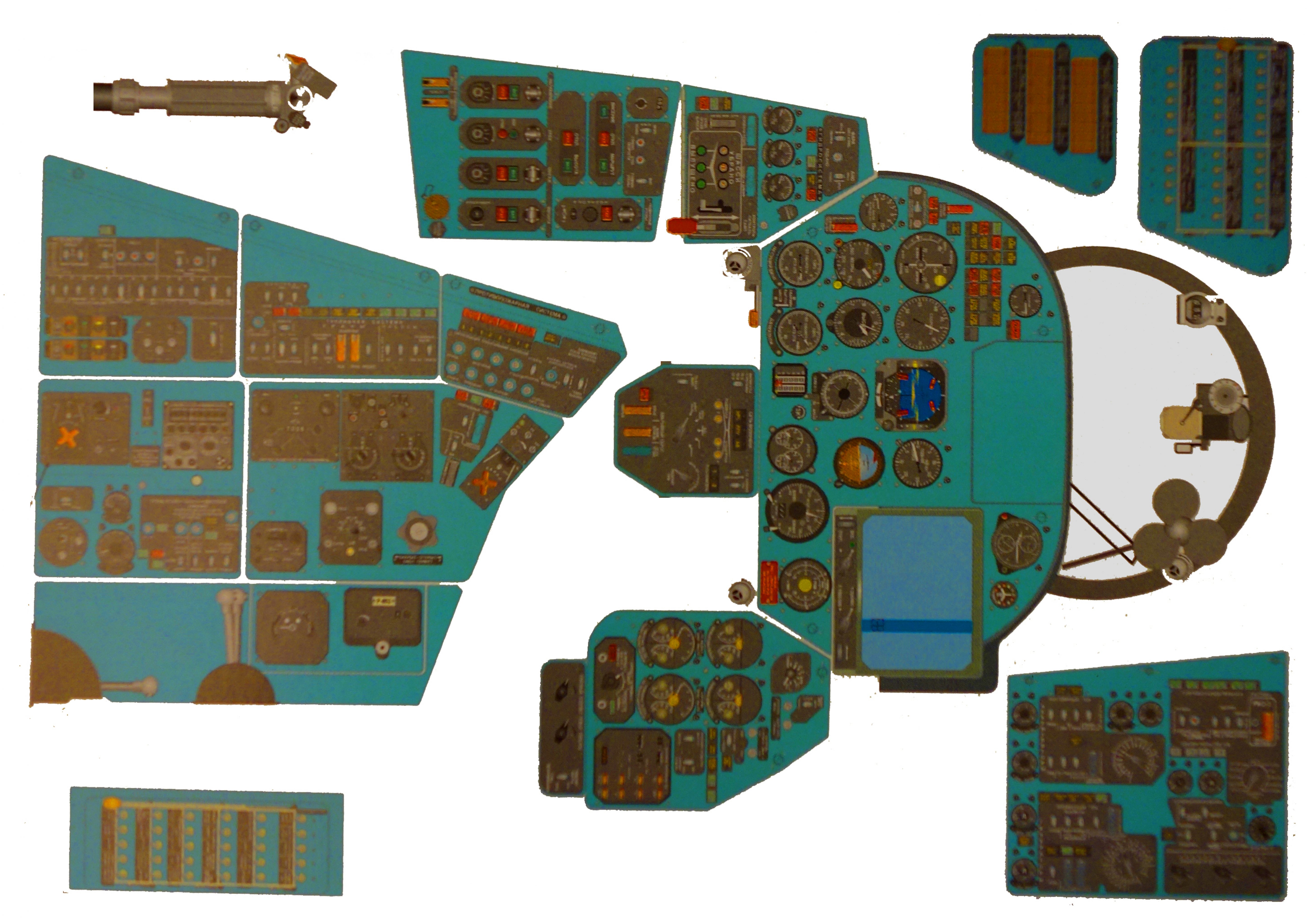
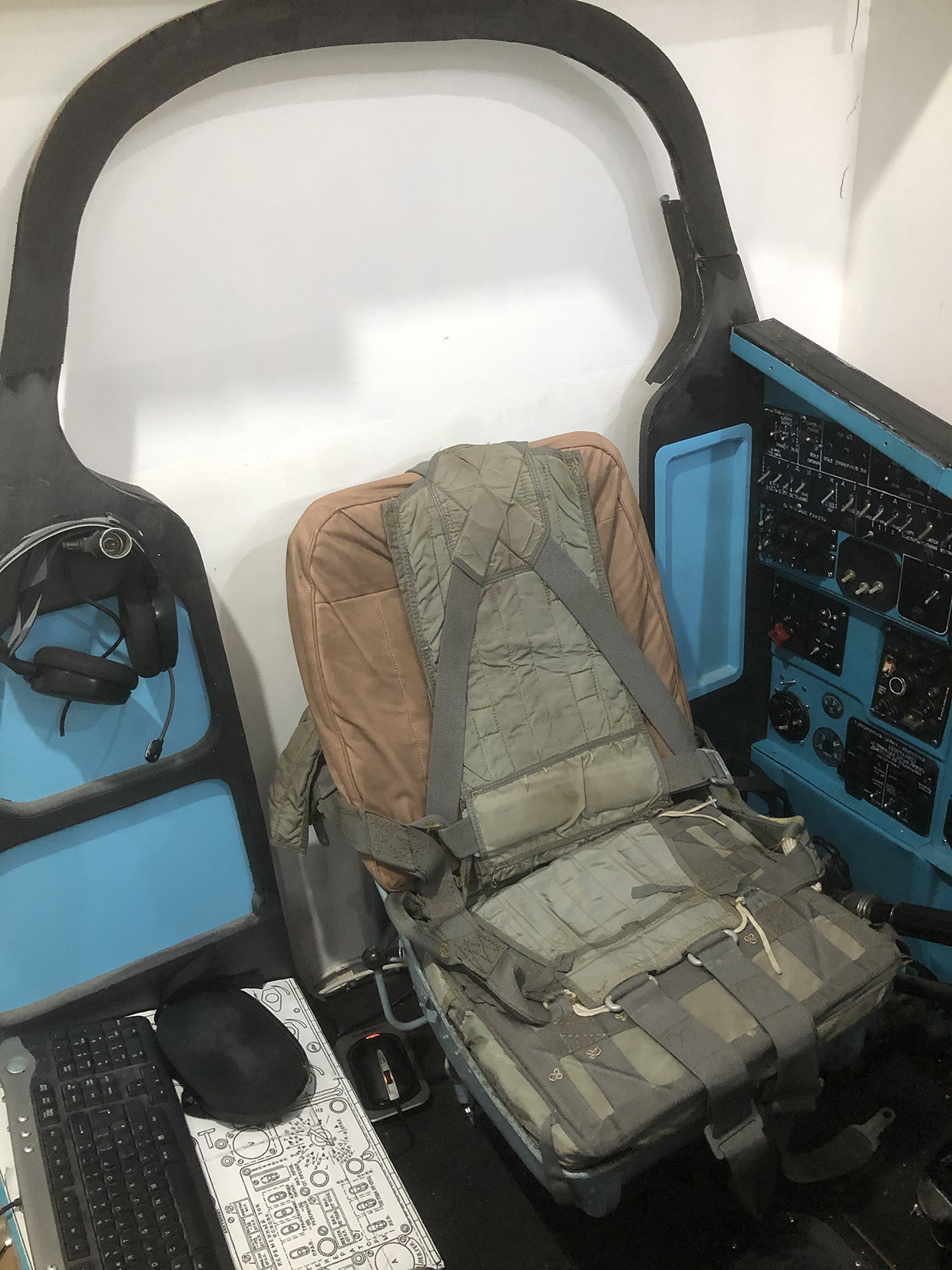
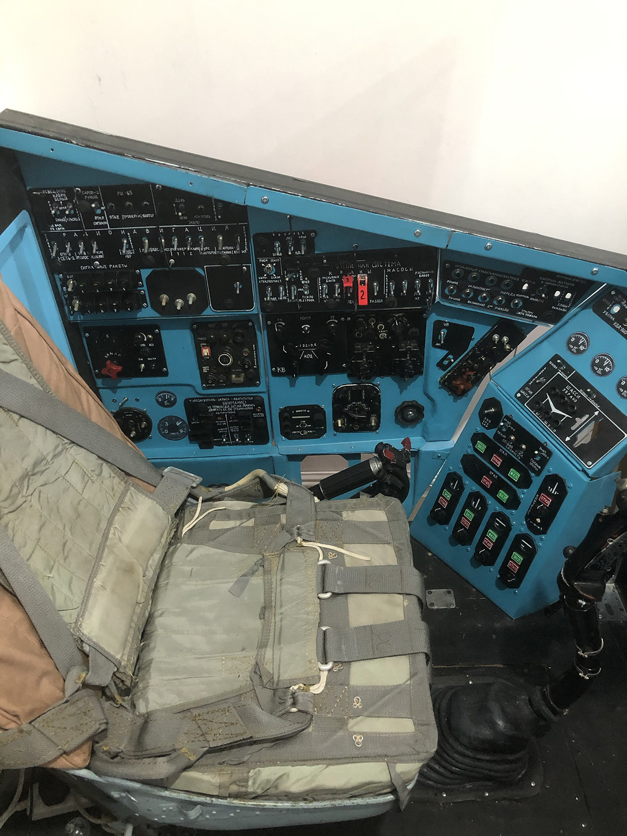
Mi-24 Pit Enclosure and Panels Once I started down this rabbit-hole, I realised I was going to need some accurate measurements or ideally plans/blueprints to work from. Having scoured the web to little avail, I discovered that The Helicopter Museum at Weston Super Mare in the west of England have a Mi-24V in their collection. I rang them up and asked if I could visit and gain access to the cockpits of the Mi-24. They said yes, so long as I came on a quiet day. So I arranged a date, and set off from London early one morning. Despite having a notebook and tape measure in my pocket, I was so excited once I was in it, that I forgot to measure even one part of it.... But I took a lot of photos, and I share some here via a Dropbox link. The museum is massively worth a visit, and the folks who run it very helpful and friendly. You should all go! Helicopter Museum pics I had also been shared a library of Mi-24 reference pictures by a 3D CGI artist called André Cantarel, whose personal project to model the 24 I had come across online. Going through those, I found several very useful images, mostly from wrecked 24s which showed photos taken of panels very squarely so there was little distortion by perspective. One of those became my main starting point to build from by scaling it up to 1:1 scale using an authentic ARK-15 unit as my yardstick to match to. Combining that with illustrations of various panels from a Mi-24 manual, also found online, I was able to scale up all the panels from the Pilot's cockpit. I did this in Photoshop and created black and white line images, printed off onto A3 paper and spray mounted to flattened carton boxes. Black and white line 1:1 Mi24 cockpit panels. Which resulted in this mock up. Its like a large but simple 3d jigsaw. Paper and carton mock up of Mi-24 pit. Having thought I would manufacture the pit out of MDF, I soon realised it would weigh a ton, and be very hard to move or manoeuvre while working on it. But I built the base out of MDF for strength to support my seat and personal weight, and to be a good foundation to support panels made of aluminium sheet. I have done limited work before in metal, but bought some aviation tin-snips and some very cheap panel-beating hammers, and ordered some aluminium from eBay. It proved very simple. Most of the panels are formed very simply with straight folds and drilled holes. Using my full size left wall print-off, I created templates for each panel. Cut to shape, edges sanded and smoothed, surface scoured and primed, I then sprayed them with "Montana Gold" brand NC-Acrylic spray paint, colour "Dolphins". Panel labelling switch surrounds are from Black 2mm styrene sheet. My sheet metal forming system is little more than a sturdy table top, some lengths of battening, 2 or 3 G-clamps and a rubber hammer. Clamp the metal sheet so that the part to fold is over the edge of the table. Align the batten with the same edge and clamp in place. Strike with the rubber mallet in glancing blows and gradually bend to shape. Not to much in one place else the surface can stretch and get distorted. For some more contoured parts, I cut MDF offcuts to shape and hammered over those. Aluminium is very forgiving and can be stretched and shrunk over complex formers. A made a frame using dry-wall metal studding channels from which to suspend the aluminium panels. The back walls either side of the pilot's chair are in MDF as strong supports for the left wall framing, which leads forward to the dash-panel mount over the pedals. More on the overall enclosure later.

-
Hi Punk, I use both Bodnar and DCSBIOS. My main controls, cyclic and collective are on Bodnar board, plus all their respective switches and levers. But I moved on to DCSBIOS once I started back engineering some authentic panels, and found Bodnar boards too limited in functionality for that. DCSBIOS is complex, complicated and frustrating at times, but once cracked, it’s a brilliant system. I have a couple of spare Bodnar boards now, but I will use them up for simple switching systems, eg electrics management panels, on off switches etc. My point being, it’s ok to mix these systems. Just keep a record of everything! Mole
-
Спасибо за миниатюру. Мой кокпит на 99% соответствует изображению, которое вы показываете. Я должен добавить тумблер и кнопку на панели двигателя, а также некоторые другие небольшие дополнения. Я очень рад такому развитию событий! Спасибо за фотографию! Mole
-
The map holder uses a moving transparent tape, not a light. The tape has a red cross reticle on it It moves similarly to the way a CnC machine moves the machine head, so it is mechanically driven. The scale can be selected and different scale map cards inserted. It is a Doppler/Inertial system.
-
The Collective with Magnetic Brake system I acquired through a source in Chelyabinsk an authentic Mi-8 Collective complete with adjustable friction damper and Engine Condition Levers (ECL). The Mi-8 Collective lever is about 10 cm shorter than that of the Mi-24, but otherwise appears much the same in function. In the Mi-24 pit its cradle is covered over to protect from junk falling in, unlike the Mi-8. The lever has three pus button switches and a 4-way hat. The switch by the thumb releases the hydraulic brake so the collective can move up and down. The friction damper can be adjusted from loose to locked. The twist throttle also has a twistable damper which goes from free to locked. I designed a magnetic braking system for the collective brake which would use a piece of steel plate cut to shape to interact with the electro magnet. The electro magnet would be turned off by the thumb switch, allowing the lever to be moved. With the mag brake on, the lever does not move, even if the friction damper is loose. This means that in flight, the left hand can be taken off the lever to do other tasks, but also that the thumb must be depressed during manoeuvres using the collective a lot. When the cyclic and collective are fully trimmed out, and the helicopter in a desired flight path, the 2 levers can be let go, and they will stay where they are left. It is my intention to add the same system to the pedals. The collective on its plinth for testing position and height. You can see the prototype for the shape of steel plate to which the magnet will be attracted. Cutting the 6mm steel piece. I used something heavy to add "heft" to the feeling when in use. The collective lying on its side and you can see the shape of the plate. The shape is so that as the lever is lifted or lowered, the rotating plate will always be in contact with the magnet. The plinth without the collective on it, so the opening for all linkages and the mag-plate system have space. The placement of the Hall effect Sensor and magnet at the back of the collective lever. The side showing the linkages from the Engine Condition Levers running to the back, where they turn a pair of Rotary Encoders, to record the change of position of the ECLs. The Throttle has a handy recess into which a magnet and Hall sensor can be fitted to record the change in Throttle Rotation. The magnet is set into a tube which fits inside the end of the throttle structure. Both Cyclic and Collective inputs are fed to a Leo Bodnar board which sits at the back of the pit under the pilot's seat.
-

DCS BIOS switches with cover - need help :)
molevitch replied to marek.babic's topic in Home Cockpits
Hi Marek, I have an elegant solution. You can put a Hall Sensor above the switch cover and then a small magnet attached to the cover above the pivot. When you lift the cover, the magnet will activate the switch cover in DCS. Yes, it uses a pin on the arduino, but it is great for authenticity. Mole -
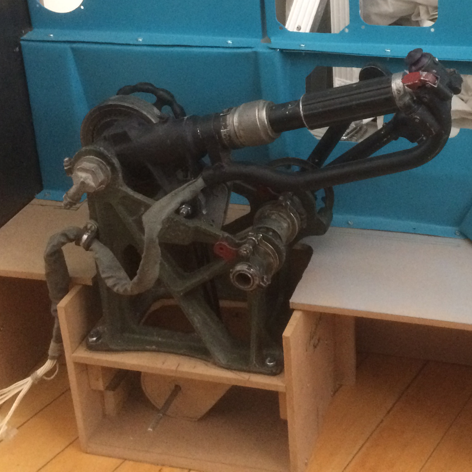
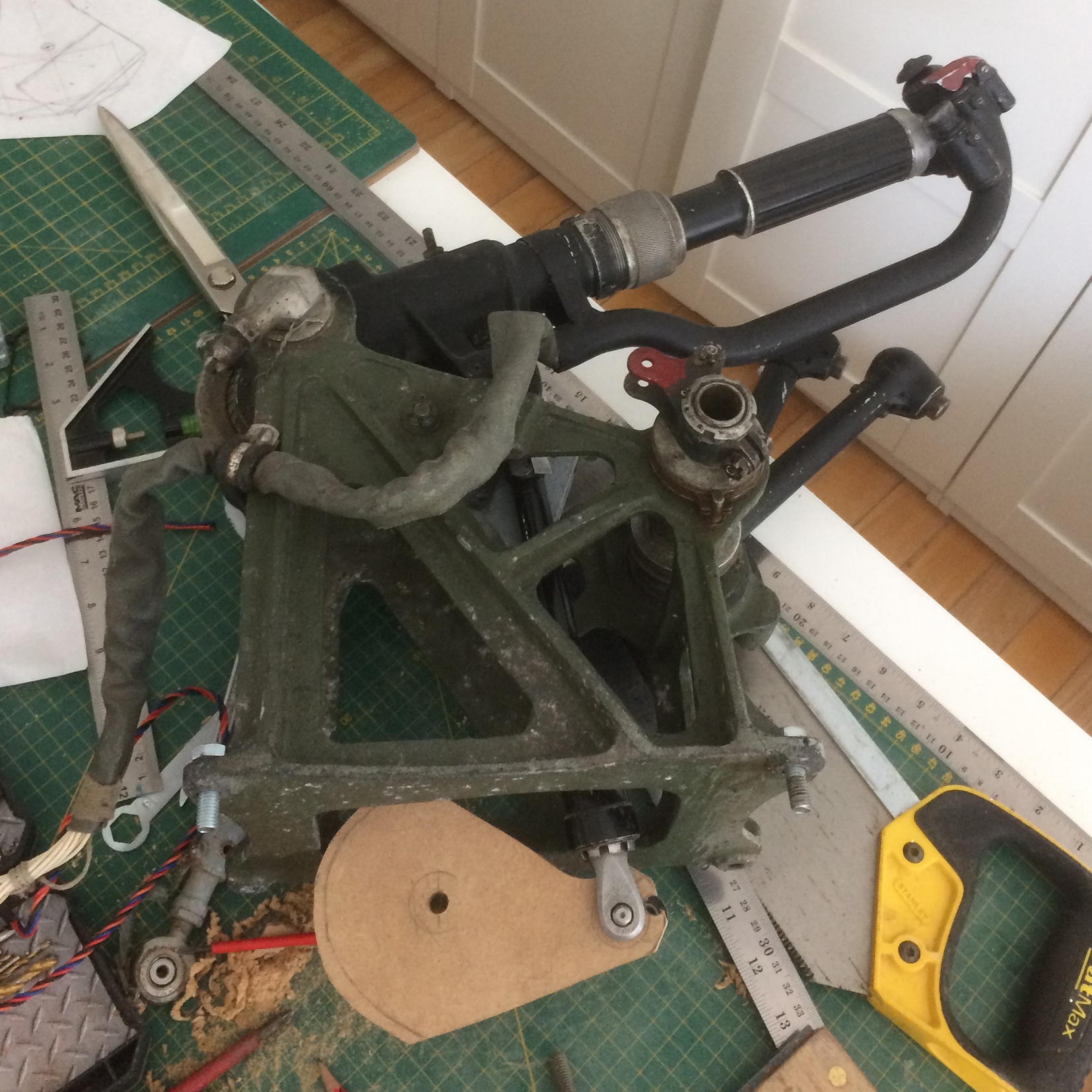
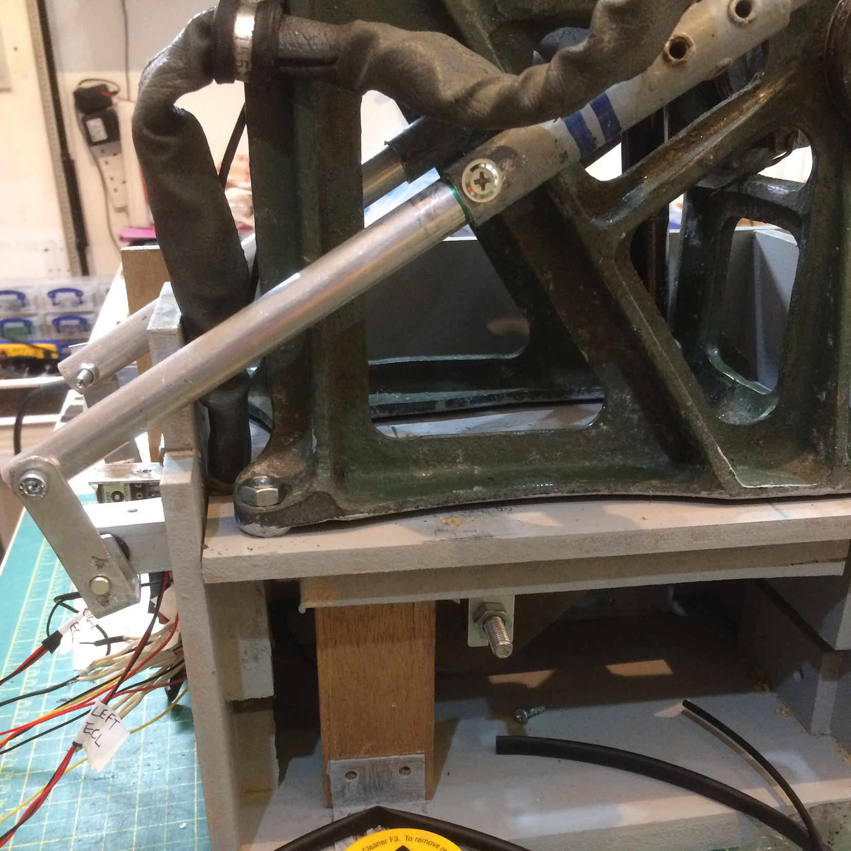
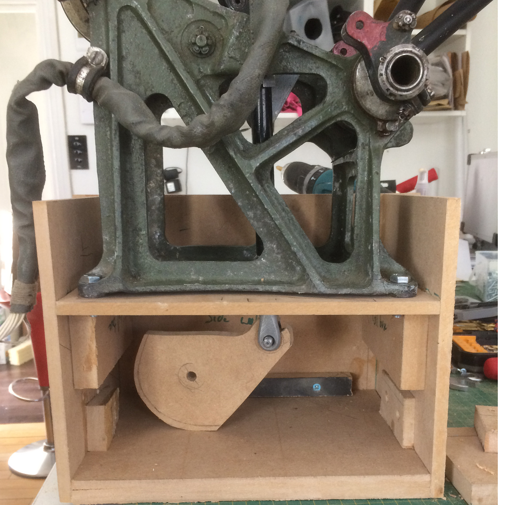
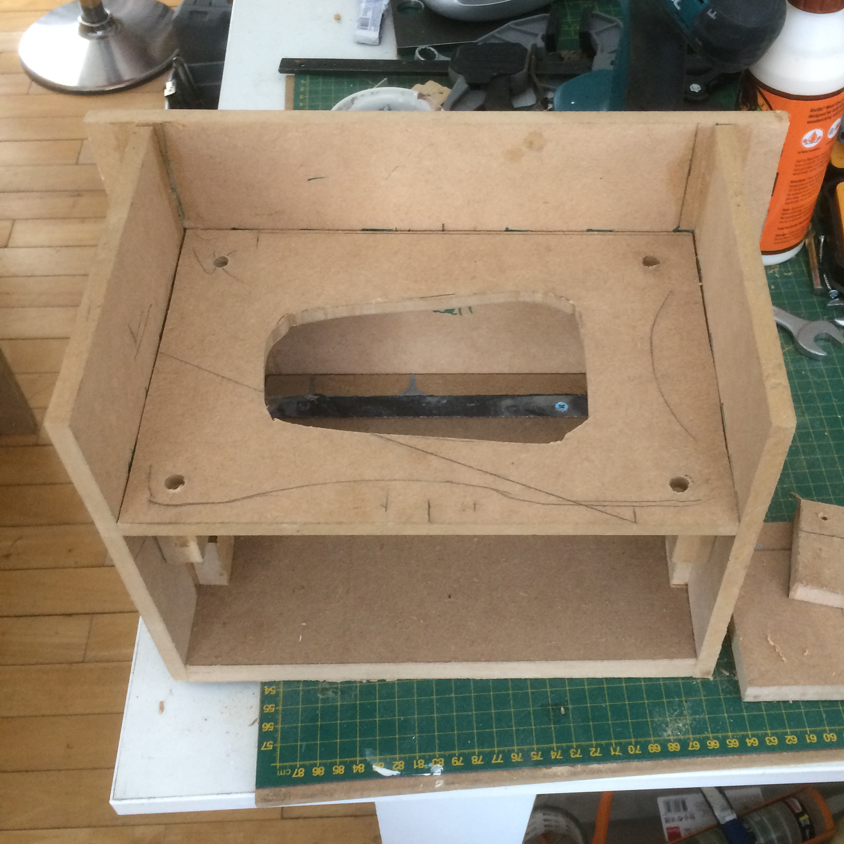
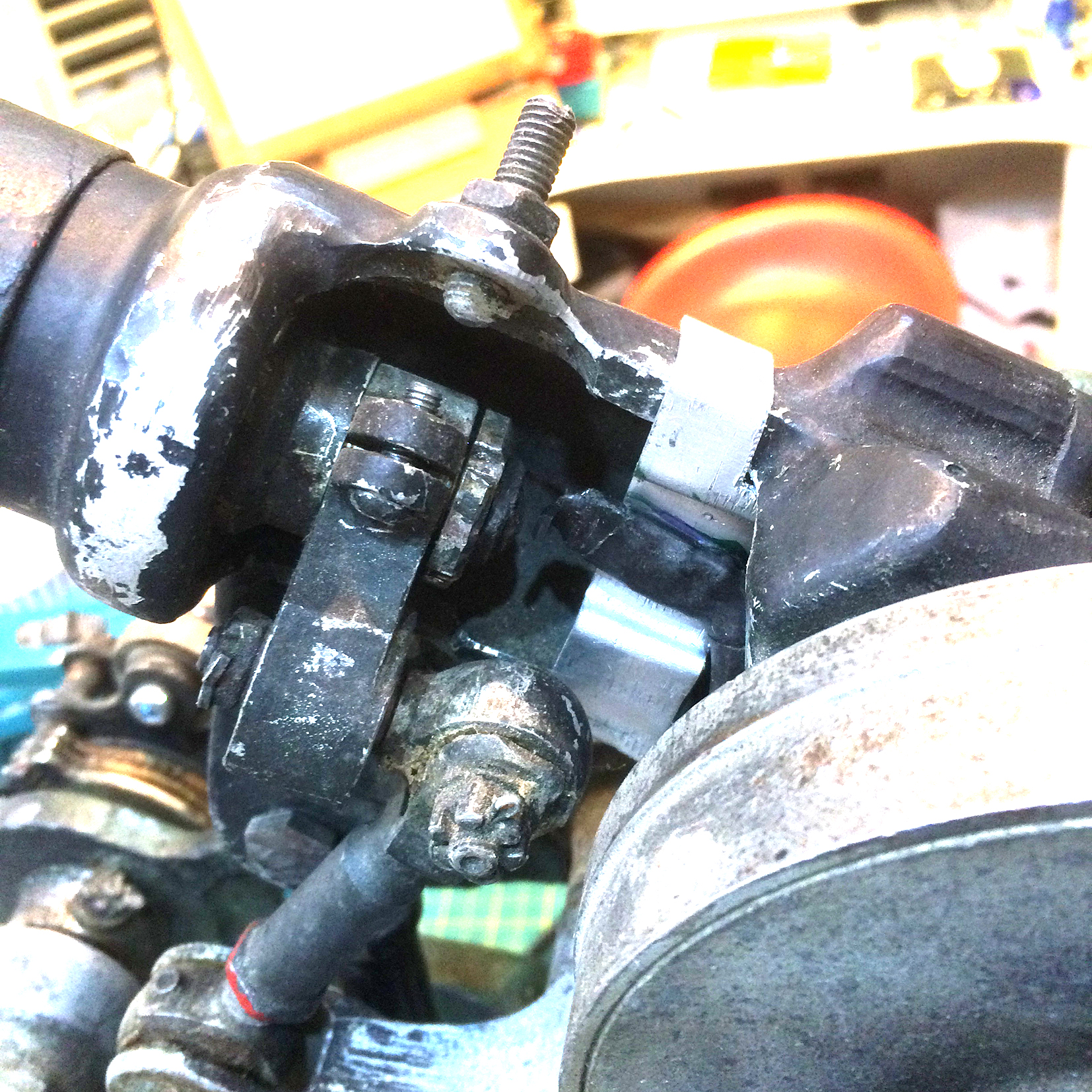
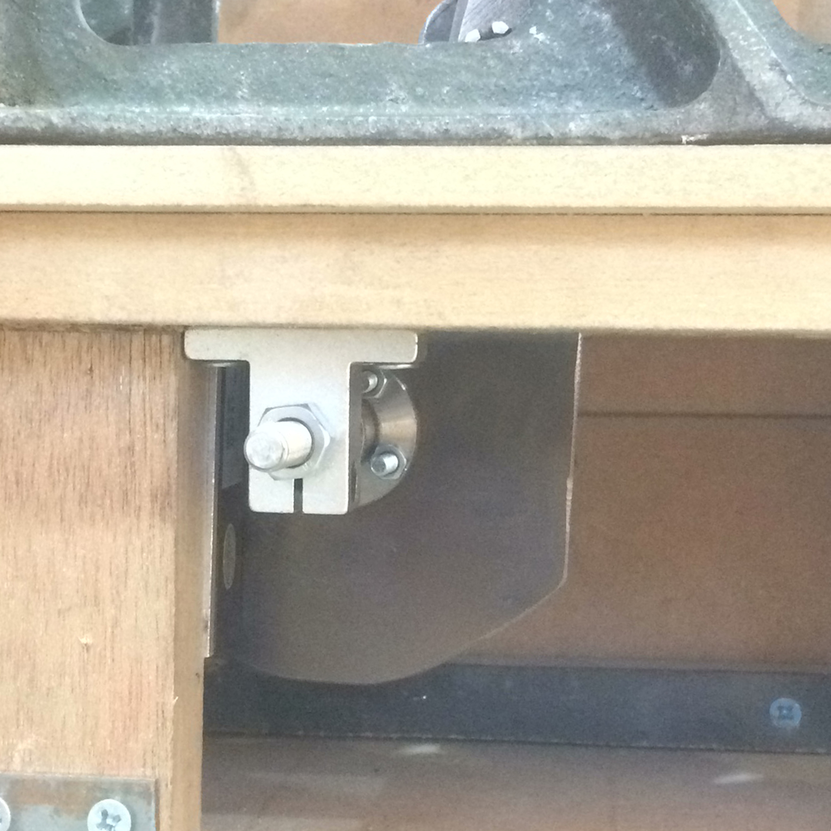
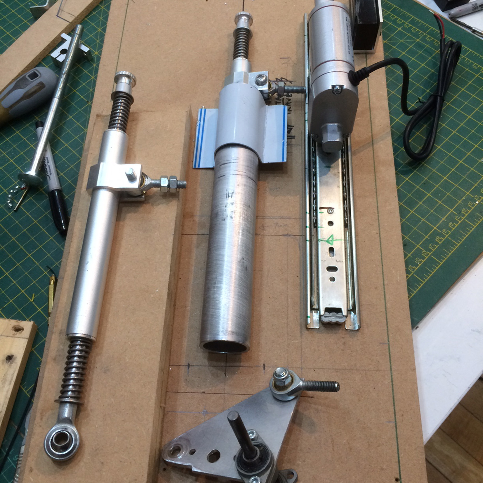
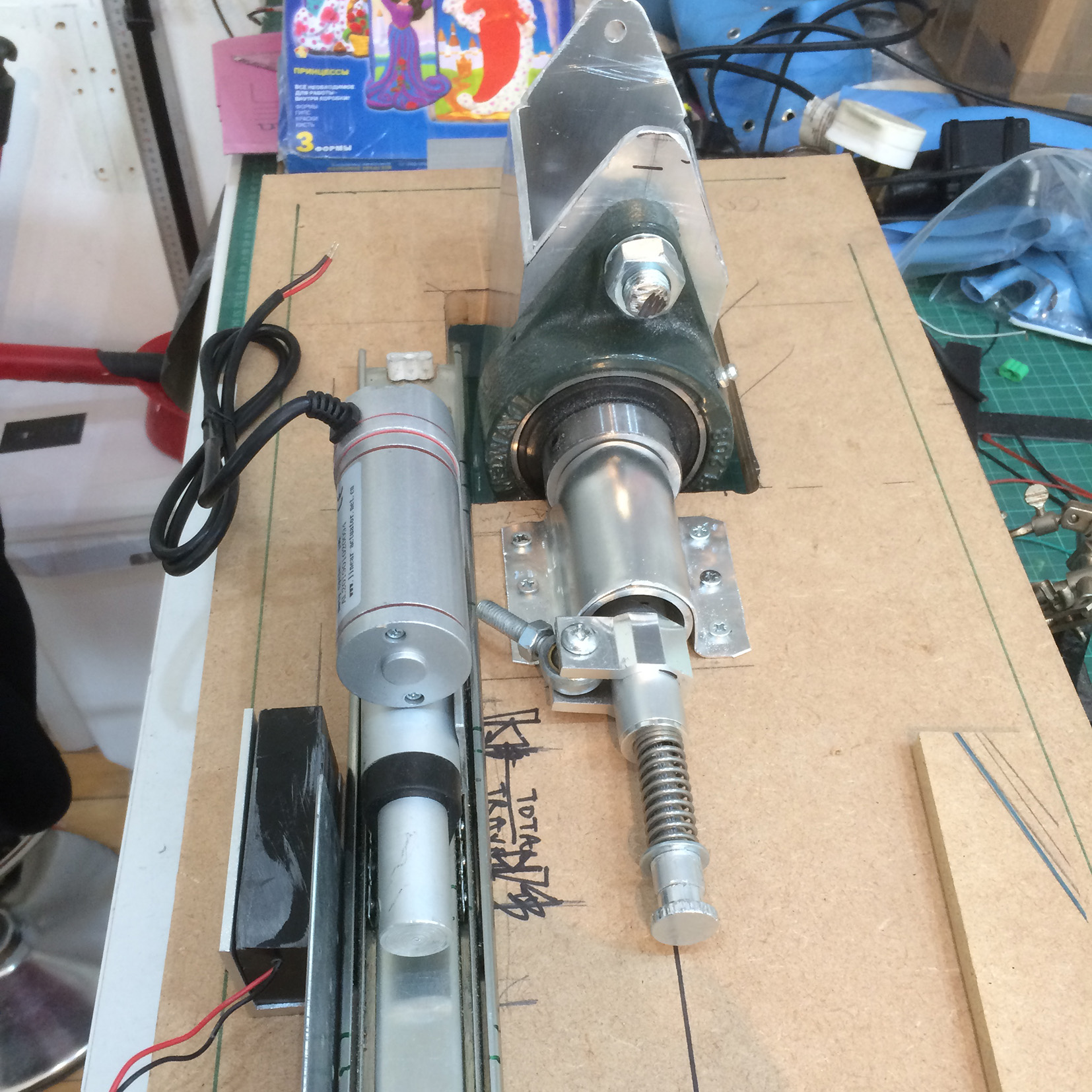
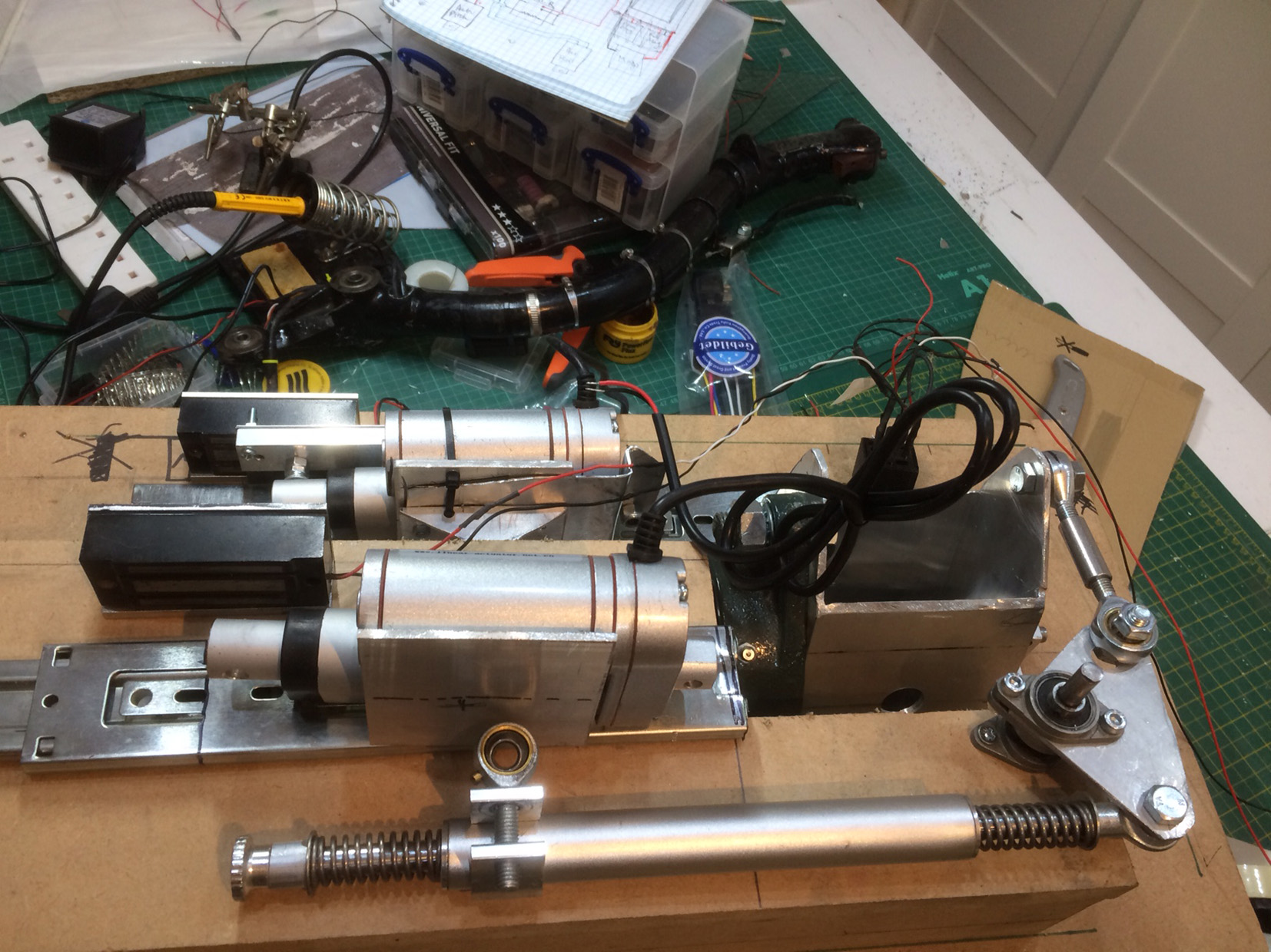
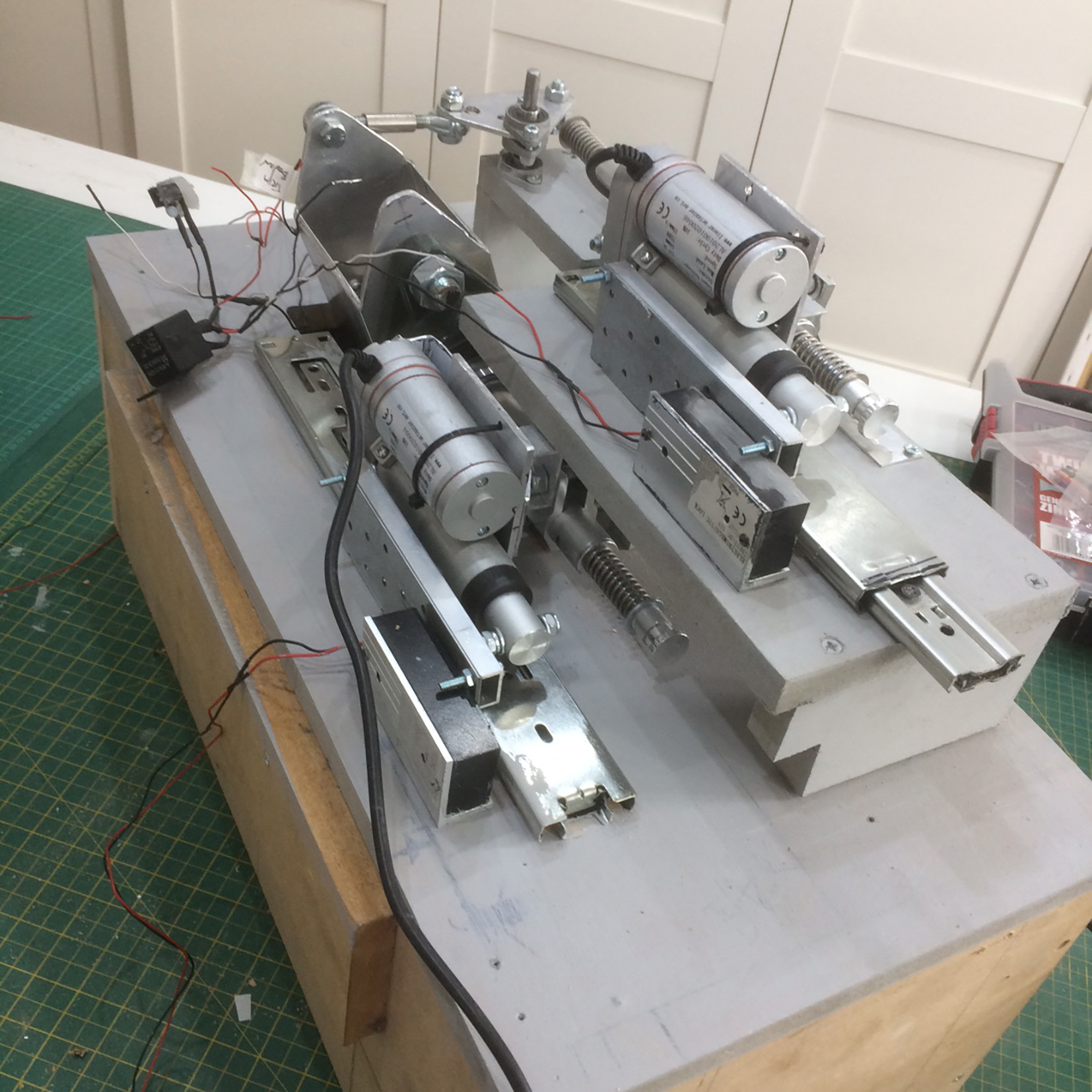
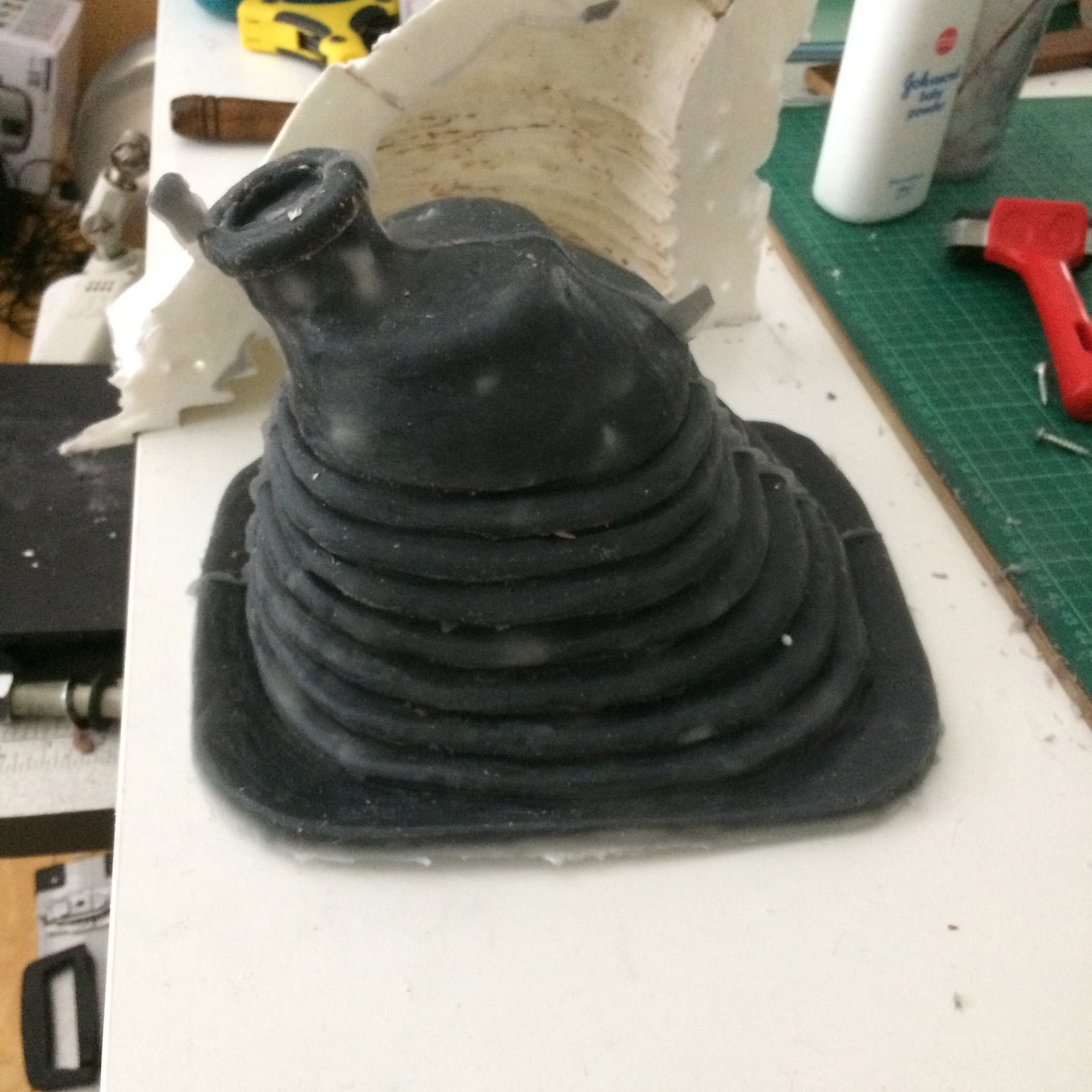
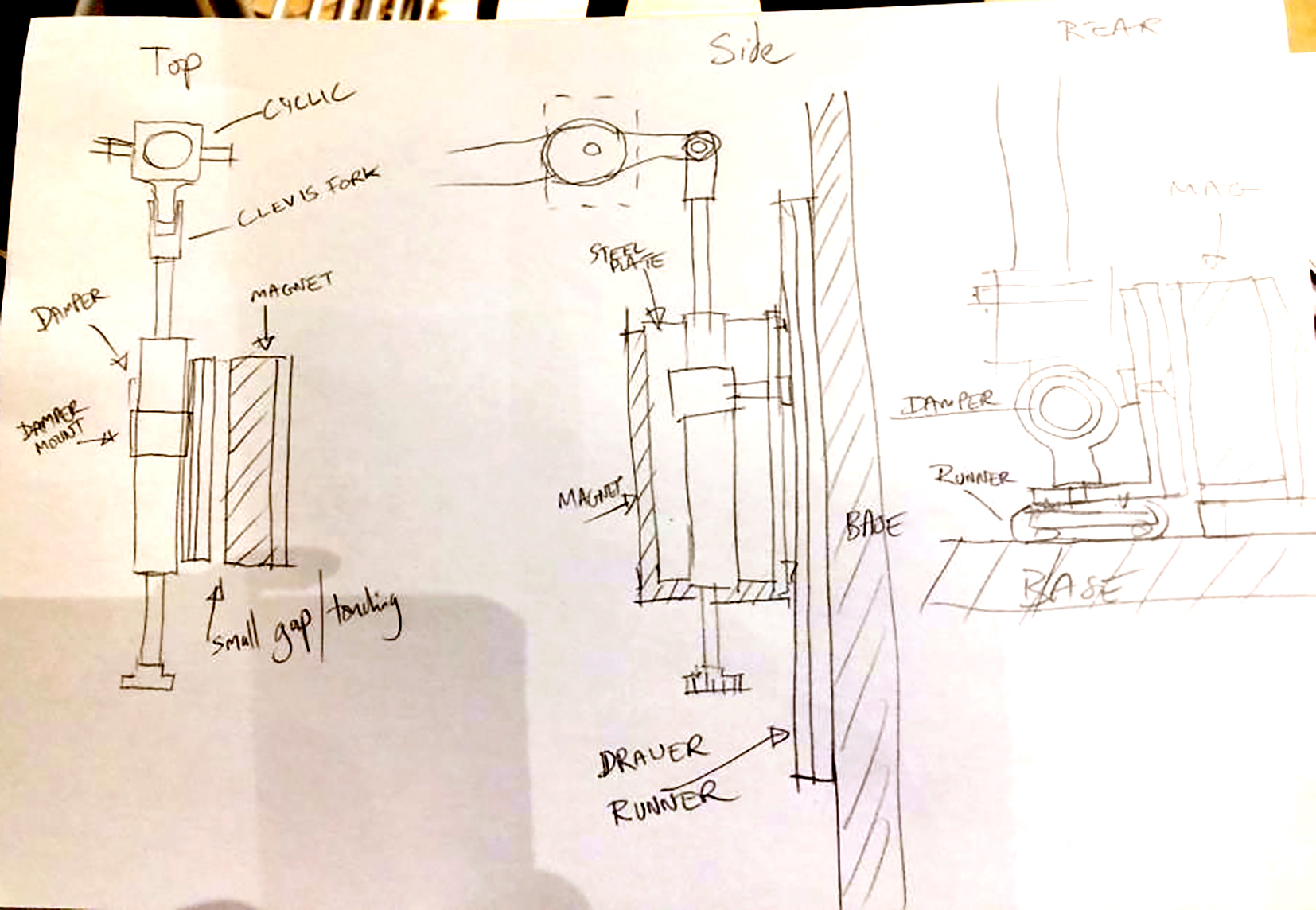
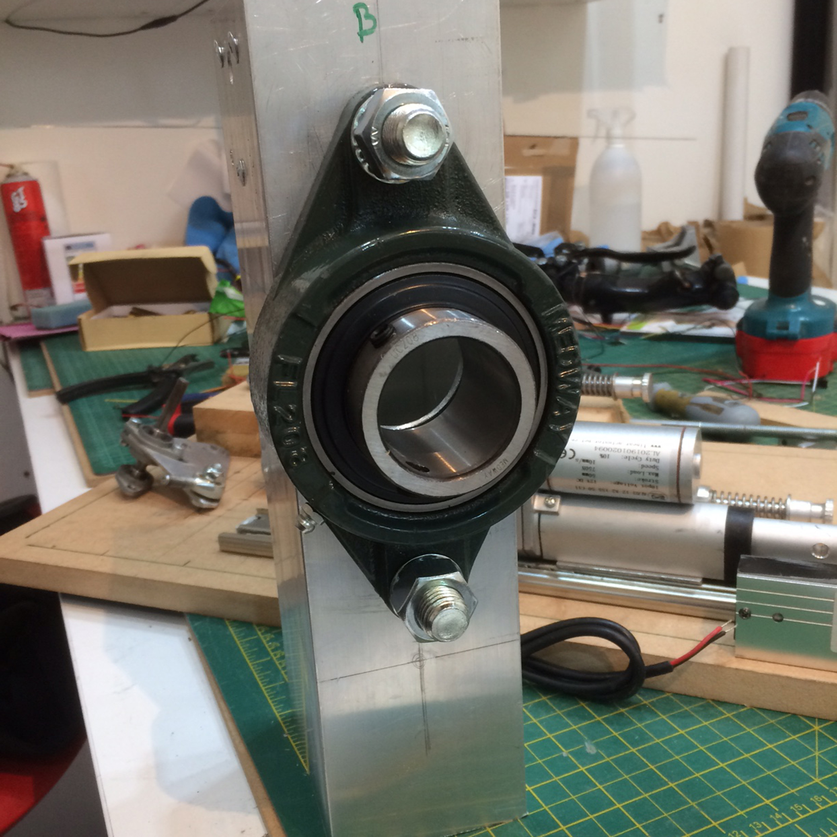
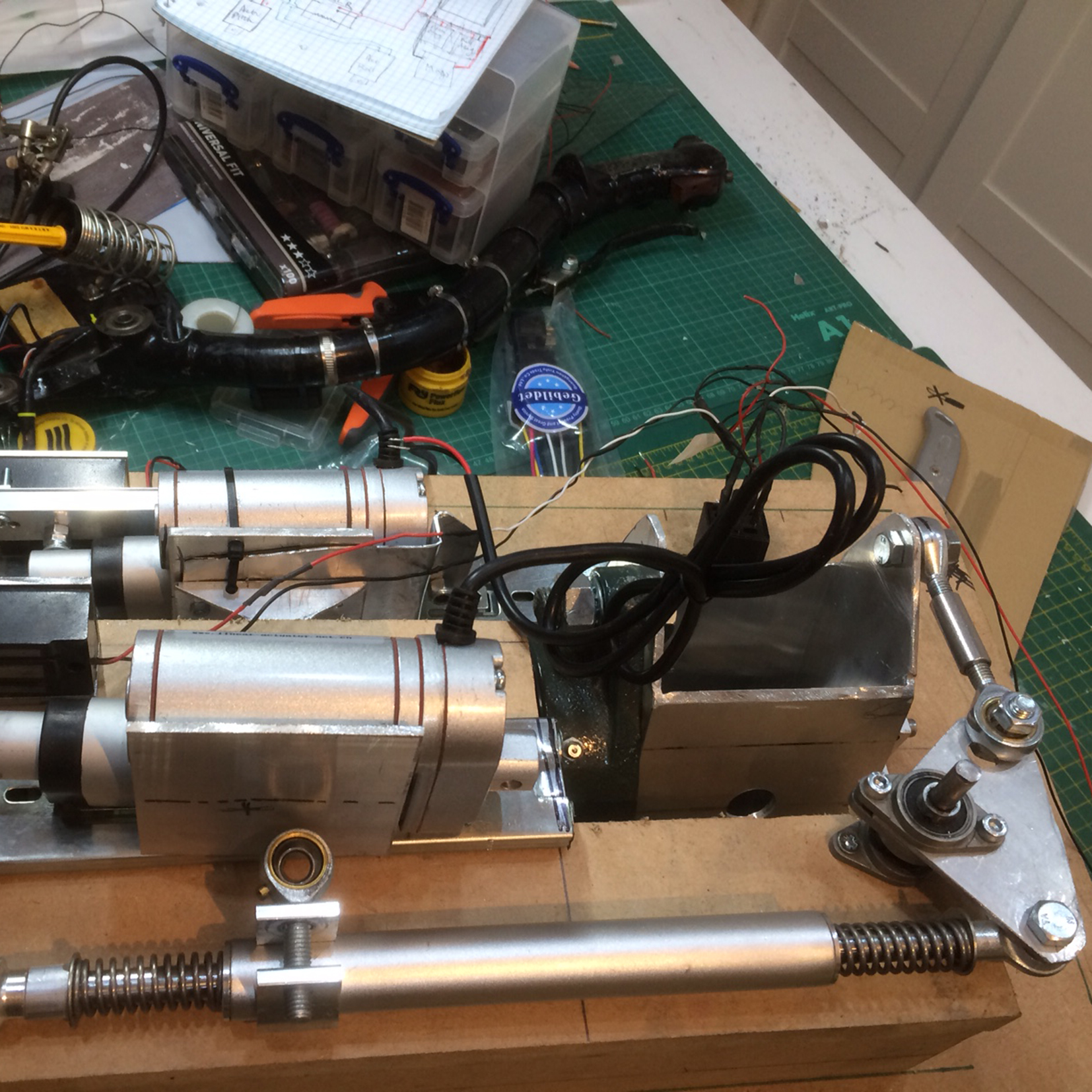
Mi-24 Cyclic with magnetic Brake and linear Actuator Trim System In 2017, while browsing on eBay, I happened upon a listing for a set of Mi-24 Co-pilot's Cyclic and Collective levers. While I was not convinced they were from a Mi-24, I made an offer and acquired them. I have covered the build that these went into before, but there have been major design changes and improvements to the first system. The first system build is covered here. https://forums.eagle.ru/showthread.php?t=188055 I will refer to some of that thread here too, but I don't intend to fully rewrite it. I did make a complete rebuild of the magnetic brake system and added the 4 way hat effected trim system referenced from this real Mi-24 video. I also decided I wanted to make each control element a separate "module" which would plug into the cockpit frame, for ease of maintenance and reduce complexity of assembly/disassembly. The new mechanism of the mag-brake and trim system would go into a box 30cm x 60cm x 23cm, and be suspended beneath the top through which the Cyclic would be mounted. I had seen a system on Youtube by a guy called David Nuss for an EC135 cyclic and wanted to emulate that system, while making it more compact.. My first mag brake system had been mounted on a floor plate with the cyclic gimbal suspended over it all. This made maintenance very hard as virtually the whole pit needed to be dismantled to get to anything. The new system would have a cyclic module, a collective module, a pedals module, a seat module, a left wall module, a dashboard and front panels module etc, all fitting together like a 3D jigsaw. The floor plinths would be made of MDF to take my weight and for stability. But before all that could be done, I would mock up the entire pit using 1:6 print-offs of all the panels and pit layout I had found in my research. This would then become a full scale mock up using 1:1 print-offs, scaled by reference to an authentic ARK-15 radio-compass unit, and spray-mounted to corrugated card. From this, all positions of collective, cyclic and pedals, seat height and cockpit widths could be verified before any expensive materials were cut and assembled. I then made plan drawings of all the floor and broke it up into parts for the modules. I then disassembled my working magnetic brake cyclic system for a complete rebuild using all the existing parts, as well as adding to them new parts required. I made a gimbal using box section aluminium. This would be pivoting in the roll axis using a massive bearing block I got on eBay for £10! Through the bearing would pass the connecting rod for the pitch axis. The Force gradients are made from repurposed Motorcycle steering dampers with compression springs at each side. These are attached to Linear actuators. And the linear actuators are mounted on heavy duty drawer sliders. The linear actuators have a magnetic plate attached to them, and these are clamped by electro-magnetic force to an electro magnet fixed to the base. In this way, Trim can be adjusted by releasing the mag-brakes for free movement of the cyclic in both axes, sliding on the drawer runners. When the trim button is released, the mag-brakes re-engage with the steel plates, holding the cyclic. But also, corrections can be made using the cyclic hat switch to activate the linear actuators, whose pistons push or pull against the electro-magnets.(!) Design of the mag-brake system. The gimbal using box section aluminium and bearing pillow block. First test assembly of Linear actuator mounted to drawer runner, not yet attached to the force gradient. Pitch axis complete, Roll axis system with Bell crank being test assembled, attachment to actuator not yet designed! Almost finished cyclic mag-brake trim mechanism before final wiring up. More on this as I find the pictures on my system! Meantime, here are 2 videos showing the cyclic system in action, underside, and topside. So that is the cyclic basically done. What it needed of course was a corrugated rubber boot to stop crap falling into the mechanism. So I made one.... How I did that will be a separate thread.
-
Hello Gentlemen, I have for the past 18 months or more been developing a sim-pit for the Mi-24 module, when it comes. Some of you know about this, and some have been asking for information about how I did some of the parts, or have been asking for reference images, plans, dimensions, and other information. So I have decided to put it all in a lengthy blog-like thread which I hope will be helpful and not too boring. The risk also is that I look like a big fat show-off, and if that appears to be the case please forgive me. I am doing this to save making multiple responses to different enquiries. (That's my excuse, and I am sticking to it.... but it is probably mostly vanity). It is hard to begin. My pit started off with a Warthog HOTAS set a decade ago, but I soon graduated to hacking MSFFB2 sticks following PeterP's method. A few simple button boxes and Bodnar boards followed from that. With practice came confidence. I decided to try and build a fully functional Magnetic Brake system similar to those used in the UH-1H and the Mi-8, and other helicopters.This became a project which is now on its third iteration, and has now developed to a high level. I do not use 3D printing, I do not have a CnC machine. I fly in VR (currently) and want to have physical switches and knobs and dials to interact with. I also want it to look authentic and damn' good! That was not my initial intention, but once I started to achieve a certain result, I realised that I would want to try to achieve that with much more of it. I have been flying the Mi-8 predominantly, since it came out, and now see it as a training for the Mi-24 to come, with many shared or similar systems. The DCS-BIOS I am running is therefore for the Mi-8. To simplify this thread, I will be breaking it up into modules as it will take some time to do. 1. The Cyclic with Magnetic Brake and Linear Actuator Trim. 2. The Collective with Magnetic Brake. 3. The Pit Enclosure and Panels 4. Authentic Soviet Era Equipment. 5. Connecting to DCS via Bodnar and DCS-BIOS. 6. Making Things! 7. Anything Else.... 8. Appearance of Work in Progress. So to start, here are a few pix of the current status of the project. I hope you enjoy my work, and please feel free to ask questions about it. I cannot supply plans, but I do have a sketch and photo record of much of the build, and I visited The Helicopter Museum in Weston-Super-Mare UK for valuable research and an opportunity to sit in the cockpits of their Mi-24. I will be adding to this thread over the coming days and weeks. Mole
-
Mi-8 controls frozen during training
molevitch replied to Fang333333's topic in Controller Questions and Bugs
Hi Fang, I realised what the problem is. The instruction to “centre controls” refers to your physical sticks, not the ones in the cockpit. If your physical sticks are for example off to the side and your collective raised, as soon as your engines come up to power, the virtual controls will match them, potentially rolling your aircraft over, or leaping it into the air. So, physical collective down, physical cyclic centred, pedals centred too. To match the positions of the virtual sticks before start up. Mole -
Hi Electratill, Make sure your soldering is very cleaned up with isopropyl alcohol. I had similar problems and found this can fix things. Mole
-
Mi-8 controls frozen during training
molevitch replied to Fang333333's topic in Controller Questions and Bugs
You have to start up. The controls are hydraulic so will not move until hydraulics are functioning. Make sure collective is all the way down and cyclic centred. Once you have one engine running, the controls can be moved. -
Hi Bartzebrat, I had the same problem.... Classic fix for me. Turn the PC off, and on again. Then all the Plugins listed too. Mole
-
DCS-BIOS: Strange behaviour over RS485 Network
molevitch replied to molevitch's topic in Home Cockpits
Attn. HanSolo: Timer issue. Hi Hans, Please ignore the PM I sent you. I found a new Timer library which works now, so all good. The ARK-9/15 is now fully functional on the RS485 network. Thank you once again. I feel I should start a new thread about my Mi-24 pit now. It has changed a lot with many new features, some probably worth sharing, or at least, showing off.... Thanks as always, Mole -
Can you post a pic of what you are looking for?
-
In fact they had to lengthen the barrel of the guns to prevent the pilot in the gunner seat getting concussion.
-
DCS-BIOS: Strange behaviour over RS485 Network
molevitch replied to molevitch's topic in Home Cockpits
ARK-9/15 Amended (improved!) Sketch by HanSolo Hey Hans, Once again your kindness astonishes me! I have yet to test it, it’s still early and I saw your reply late. Thank you, I will give it a go this morning. Regarding timer.h, the sketch worked over USB without it, and I had only just put in the library include before I sent it here. I should have read a bit more about it! I used a stripped down version of the old code to make a sketch for another panel, a 20 position channel/frequency dialler. It too uses 5 mechanical switches to output binary codes. Analogue systems before silicon became the norm. I love this old stuff, and getting it to talk to digital PCs. The next few panels are all basic on-off or on-off-on switches and variants, more simple than challenging, but I have one more Soviet era unit to decipher. Hopefully ED/DCS will deliver the Mi24 sooner rather than later. Then I hope some DCSBIOS whizzard will do the code for it! Very excited. Thank you once again, and I look forward to talking to you again, (no doubt...). How is your own pit progressing? Is it complete? (Are they ever. :music_whistling:) Mole -
DCS-BIOS: Strange behaviour over RS485 Network
molevitch replied to molevitch's topic in Home Cockpits
Hi Hans, When I run the Master outside DCS, I see a constant stream of the dials outputs being checked and updated. If I flip a switch which is on the same sketch/Mega there is no sign of it, but if I flick a switch on one of the other panels on the same network, it shows in that Master data stream. I have included the Timer.h library. As I say, the Sketch works as a stand-alone panel, so I could run it simply on it's own outside the network, but it should work on the network really. Hi Outbaxx, Yes, the dials work, but the switches do not.... Puzzling! Thanks guys for your interest and help, I have put the code down below in the Spoiler tag. Mole