molevitch
-
Posts
532 -
Joined
-
Last visited
Content Type
Profiles
Forums
Events
Everything posted by molevitch
-
I thought this thread is supposed to be about “What we know about the ED DCS Mi-24”, no? What do you think @BIGNEWY? (I’m with you on this @S.E.Bulba...)
-
Thanks BlackLibrary, I will check it out and let you know how it goes!
-
While waiting for the DCS-BIOS Discussion thread to be updated/added, I wish to ask for some help here. I am trying to add Electrical system code snippets for the mi-8 to a sketch. When I try to use "115V Inverter" and "36W Inverter", it will not compile. From what I can tell, the program does not like a variable which begins with a number. Any guidance on fixing this would be much appreciated. Everything else works as intended, but it means I cannot run a cold start without having to flick those two switches up using a mouse in the virtual cockpit....
-
Nice to see a recorded work up of your project.
-
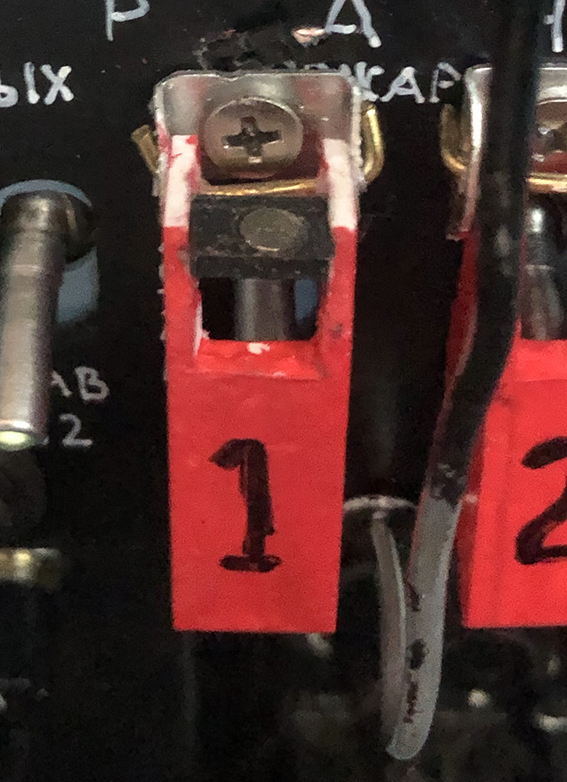
Here is a pic of the first prototype. It works, I will probably swap it out when I feel like it! (This was hand made from plastic-card, before I got the 3D printer....)

-
I used a hall sensor mounted discretely behind the guard cover pivot, and a tiny magnet mounted in the back of the guard-cover. Flip up the cover, the Hall sensor signals to the Arduino and on to DCS. Same when the cover is closed. Also, my guards have no springs in them, but I designed the pivot point to have a notch in the shape of a cross and the cover to have a pin and bar. The springiness of the cover’s sides engage that bar in the notches, when the cover is either horizontal or vertical, closed or open. i bought some of those “missile switch” with covers. Trouble is, the closing cover turns the switch off. Useless. I tried drilling some out to accommodate the toggle lever. Not much better. Threw the covers in the bin, designed my own. Now look like the real things.
-
Example of cardboard and paper mock up. Scaled using dimensions of an authentic component bought on ebay, a radio compass unit measuring 14cm x 14cm. Some images from an mi-24 manual, and some from stripped down photos. The cardboard version is from March 2019. Today, my pit is nearing completion, but still probably 3 more months to go.
-
I was about to mention that too! Fusion 360 is just a superb program for this kind of work.
-
There are lots of posters of cockpit layouts. https://www.ebay.com/itm/Harrier-AV-8B-Baseline-Cockpit-Arrangement-Poster-McDonnell-Douglas-VTOL-Print-/143188294740 buy one, or scale an image grabbed from the net in Photoshop or similar graphics package. Find an object to scale to from the real world, eg the diameter of a gauge or the width of the cockpit. In my experience, engineers/designers prefer whole numbers rather than fiddly fractions, so a gauge is likely to be 8 cm or 3.5” diameter. Print off the panels on paper, 1:1 scale and glue them onto corrugated card sheet (disused cartons, Amazon supply them with every delivery!) and assemble. You can then sit in your cardboard pit and assess the results before going to the lengthy and expensive process of creating the working model. Also, get as many “square on” photos of everything you want to model. By which I mean, not shot at an angle, so yo have a good flat reference with minimal perspective distortion. Scale these to 1:1 also.
-
I 3d print the guards and use a variety of toggles, mostly from eBay, including Russian Soviet era models.
-

What does the "rod" at the front of the gunners cockpit do?
molevitch replied to Milkyblue's topic in DCS: Mi-24P Hind
The point being, its a Pitot Tube..... -
:thumbup::thumbup::thumbup:
-
Late Summer Update The past few months have seen a slowing down on pit development, a hiatus caused as much by real world work, Covid Lockdown activities, and a resultant shift in lifestyle. (Curiously, less time available for pit work, and more demand to fix stuff in the house!) Now, ED has announced that Mi-24 is imminent, (relatively), and I look forward to updating my system in line with the actual module. Hopefully, some of the DCS-BIOS gurus will be quick to produce the necessary code for me to use. I will also finally get round to implementing the pedal system, with linear actuator effected trimming. I have also now acquired a 3D printer, and fellow Mi-24 pit builder, Razorback, has kindly shared some Mi-24 3D files of various components, and I have begun to run these off for inclusion in my pit. Exciting times!
-
Number and types of radios onboard the Hind?
molevitch replied to Looney's topic in DCS: Mi-24P Hind
The Mi-24 has the R-828, a Jadro equivalent and a R-863 equivalent. However, the model we are getting (currently) does not have a tuning panel for the R-863. It will have 20 preset frequencies, much like in the Mi-8, and these will be preset "on the ground". This R-828 is located behind the pilot's left elbow, the Jadro by his left forearm and the R-863 above the head of the collective, with its red-cross selector dialler. The SPU-8 is located below the ARK-15 radio compass, which is equivalent to the ARK-9 in the Mi-8 module. So Mi-24's radios will need to have presets made by mission editors for multiplayer missions, otherwise they might be unable to communicate with other airframes, or ATC/ground forces. -
Hear, Hear, Memphis! The rotary wing community are crying out for this enhancement to what are already great and much appreciated helo modules, not just the Huey. There is a large but less vocal rotary wing community who are massive supporters of ED/DCS, and we all appreciate the work that has gone into all the existing RW modules, and are even more excited about the several modules in active development. In my case, especially the Mi-24, I am literally losing sleep in anticipation of its release. The low altitude level of detail going into the Syria map suggests that it is very much oriented towards helicopter flying, and we are all hyped for that release too. So please let us have some update news on the multi-crew development for the Huey, and presumably other RW craft!
-
DCS Mi-8 is 7 years now, time for an update ?
molevitch replied to Hueyman's topic in DCS: Mi-8MTV2 Magnificent Eight
They are Heating elements. -
The countermeasures panel is above the gunners right shoulder.
-
For those who just cannot wait any longer....https://www.dosgamesarchive.com/download/hind-the-russian-combat-helicopter-simulation/ :music_whistling::music_whistling:
-
Fingers crossed!:thumbup::smilewink:
-
Hi Les, thanks for the reply. My 10 pos switch is definitely 10 positions. Old style round wafer with 10 separate contacts and 1 common. No, this is a weirdness. As I say, on the same Arduino, the other switches are not working, despite being apparently all connected correctly. I will take it apart and put it all back together again.... But with the other board, the Mega, I am running rocker switches for the Mi-24/8 Autopilot system, (or planning to, when it works), its like the system keeps missing the input, as if it goes by too fast. What I don't understand is why. I have put in a timer, but made no difference. And another weird effect. With another bank of switches connected for the fire extinguisher board, when I use my trim button to deactivate a magnetic brake on my cyclic, which is not connected to anything else except that, it triggers the fire extinguishers! :(:doh: So this one Nano that will not work on the network... it does work as a stand-alone in serial mode with an amended sketch. Which means it is a network issue, or rather a problem with my wiring....
-
Stunning work, and an inspiration to us all!
-
Hi guys, especially Hansolo, I have managed to get several slaves working now on my RS485 DCSBIOS network, but am experiencing some new problems.... I have a Nano which is used to run a 10 position switch, a momentary button, a toggle switch and a rotary encoder, to be a radio selector and tuner, R-828 in Mi8. However, it only works on 5 positions of the rotary switch, and the other elements do not work at all. I have swapped out the Max487 chip, and I even swapped out for a new Nano. The circuit is supplied with 12v via the Master Mega. On the circuit there are also a Mega (which Hansolo helped me write a sketch for, and which works fine), 6 other Nanos too. I have another Mega slave which also gives weird results. It appears to be “working” but responses to inputs are very slow or intermittent and unreliable. Any thoughts or suggestions please? I love the whole DCSBIOS principle, but sometimes I think of giving it up and converting it all to MMjoy or Leobodnar boards! (I sympathise with Lesthegrngo on the frustration of DCSBIOS, and I am not electronics “smart”, just following the work of others....) Help! Please! Molevitch
-
Looking very good my friend! I am following with great interest and a even tempted finally to get a 3D printer myself!
-
missing info Low Resistance of Mi-8
molevitch replied to edokg's topic in DCS: Mi-8MTV2 Magnificent Eight
Good to hear this! -
Starting to consider the possibility now.... I have spare bits and pieces, never throw anything out. To build the virtual gunner's pit requires a second PC, (I have two), a second VR headset (I am planning to upgrade), a joystick (I can build or use TMWH), a headphones and mic set (I have that too), oh and a second registered copy of Mi-24, (well nobody got that yet...). Then build a handful of hands on items for the gunner, AT missile guidance yoke, flares release panel, and some others.... :music_whistling::thumbup::smartass: