DanTDBV
-
Posts
41 -
Joined
-
Last visited
Content Type
Profiles
Forums
Events
Everything posted by DanTDBV
-
Polychop Simulations OH-58D Kiowa
DanTDBV replied to Polychop Simulations's topic in DCS: OH-58 Kiowa
Can't use Miles for the Kiowa. -
Hi Hannibal Your project is just so cool. I would love to do something similar, but I don't think that i have room for it. When I am done with my current controller plans I will have 3 modified T16000m's (All buttons in grip), DIY Right hand Warthesque throttle grips on a Saitek Throttle quadrant, DIY Collective, Selfcentering CH Throttle Quadrant and more. I look very much forward to seeing Your next update. Happy Simming
-
Thank you for the headsup rel4y. I agree on the 8 axes. The 16 axes was from a 2014 reply from mega_mozg. I am going the shift registers way. I already have some of Debolestis Shift register 8 and 16 boards and I intend to order a set of his 32 boards as well. I have also gotten some of the ALPS 5 Way switch boards. I also intend to get some of your 4021 boards. I expect it to be 10 of them, but I will have to see what economics allow. I found possible use for the MCP3208. It could be for something like a Forklift simulator- or Farming simulator functions controller. I assume that the grounding and decoupling is also equally needed for the MCP3202 and MCP3204 as well? I have read about grounding and decoupling and get the gist of why it is needed, but just know that I will not be able to create anything of practical use with that knowledge. Just as I know that I do not have the motorskills for SMD soldering. Yeah I have ruined a couple of projects learning that. Happy Simming
-
Thank you very much Debolestis. I very much appreciate it and look forward to being able to order the resulting PCB’s. I am sorry that it has taken me this long to reply. Life have taken its share of time. My Grandmother lost a lot of weight in December. In the middle of January she was diagnosed with cancer and trouble with some of her inner organs. A first operation didn’t help and my German cousin from Australia, dropped everything and came up here to stay with Grandmother. My cousin and I hadn't seen each other for 38 years, so I went there to spend some quality time with our grandmother, my cousin and her daughter. A second operation has helped and Grandmother can eat and is feeling better and my cousin has returned to Australia. Happy simming
-
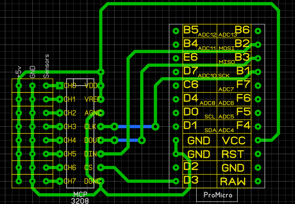
From the descriptions at Digi-Key the CI/P MCP320X chips are 12 bit and the I/P MCP320X chips are 10 bit. One reason is to free up available pins on the Pro Micro and another is to minimize the number of wires needed from a Pro Micro board in the controller base to a MCP and one or more shiftregister boards in the button/minijoy grip on a stick or collective. If my assumption that I only need 1 ground wire and 1 VCC wire to connect the MCP and the first shiftregister is correct, then I will only need 8 wires from a Pro Micro in the base to an MCP and first of however many shiftregisters and buttons I can fit into a grip. To be more precise, what I am wishing for are boards with input connections for wires from an Arduino board and output connections for wires to the supported number of potentiometers. For my Warthogesque righthand grips on Saitek Throttle Quadrant project, I currently intend to put the Pro Micro in an external box at the base and a MCP3202 and 2 shift registers in the big grip and a shiftregister in the small grip. I am considering converting the Saitek Throttle to MMjoy2 and then I would need a MCP3204 and a shiftregister in the base. For the collective I intend to make, I am considering 2 minijoys in the grip (4 axis), dual throttle (2 axis), collective (1 axis) and zoom (1 axis). Here I would use a MCP3204 in the grip for the minijoys and another MCP3204 for the throttles, collective and zoom. As for buttons and switches I would jam up the grip with as many buttons as possible and the shiftregisters as needed. I am considering making the base into a buttonbox, so that will also get shiftregisters. I was considering the MCP3208 for the collective, but realized 2x MCP3204 would be better for that. At this point I don’t have full use for the MCP3208, but I could find it later and others could have uses for it. I also already have some of them. Mega_mozg explains the MCP possibilities better: From SimHQ mega_mozg Quote and reply’s Quote Firmware has support for up to 128 buttons + 10 axis inputs (2 axis reserved for mouse emulation, Windows Game Controllers see up to 8 axis), number of buttons use depend on Arduino board number of pins available. Possibility to use for joystick: 128 buttons + 2 HAT's (8 buttons) + 8 axis Possibility to use for mouse emulation: 3 buttons + 2 axis Possibility to use for keyboard emulation: 12 buttons (or 15 without "mouse") To maximize the MCU (Arduino board) pins use: For axis - MCP3208 external ADC, what allow use 8 channel 12 bit (this free 4 pins on Arduino and allow 8 analog axis inputs) For buttons - shift register IC 74HC165 or CD 4021B (this free 3 pins on Arduino and allow UNLIMITED button sources chaining one Shift Register IC in another, each manage 8 buttons) Reply 1 now only one difference between any board - is a available pins count. Sparkfun[promicro] - total 18 pins, and 9 can be used for internal(onboard ADC) axis. Arduino[leonardo] - total 23 pins, 11 internal axis. Arduino[micro] - total 24 pins, 12 internal axis. PJRC[Teensy 2.0] - total 25 pins, 12 internal axis. JRC[Teensy 2.0 ++] - total 46 pins, 8 internal axis. so if you want more axis, you can use SPI connected external ADC: a) "kma200" magnetic field angle sensor + 13 bit ADC; b) "MCP3201" 1 channel 12 bit ADC; c) "MCP3202" 2 channels 12 bit ADC; d) "MCP3204" 4 channels 12 bit ADC; e) "MCP3208" 8 channels 12 bit ADC; f) "MMSENS(MCP3202+KMZ60)" magnetic field angle sensor KMZ60 + MCP3202 12 bit ADC + trigonometric math at controller, my new project digital sensor; SPI is a very easy to use, just connect power and ground from controller to ADC and connect SPI lines MISO/MOSI/SCK and CS(chip select). pin "CS" are individual for ADC, other pins is common for all ADC's connected. Reply 2 Originally Posted By: tirta "so for pro micro, there are 18 pins. If I use 6 for axis, there are only 12 pins left for buttons? so 16 axis with 64 buttons are not possible for pro micro? Are these correct?" it is correct only if you want to use internal ADC. but with two "mcp3208" connected to "pro micro" you can access to 16 axis(used 2 pins to "SPI-CS"), and you have 16 pins to buttons 8*8 = 64. The reply’s and example can be found on this page at SimHQ: https://simhq.com/forum/ubbthreads.php/topics/4024754/5
-
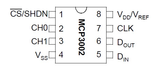
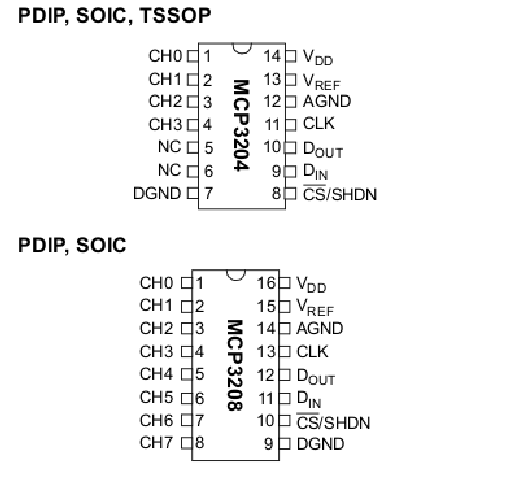
That sounds really great In this context I would like to use ordinary joystick potentiometers. I have a fair number of them pulled out off different controllers old and new. They have different shapes, sizes and resistances, but that shouldn’t matter as I would like for the outputs and inputs to be for wire connections. Just like you have it on your 4021 shiftregister pcb’s. It is not only the 3208 I am wishing for, it is also the 3202 and 3204. The MCP3202 has 2 outputs: CH0 and CH1 and can control 2 pots. I would use this for a mini joystick in a buttonhead added to an existing throttle like the Saitek/Logitech Throttle Quadrant. The MCP3204 has 4 outputs: CH0, CH1, CH2 and CH3 and can control 4 pots. It could be for a collective with a mini joystick, throttle and the collective axis. The MCP3208 has 8 outputs: CH0, CH1, CH2, CH3, CH4, CH5, CH6 and CH7 and can control 8 pots. I am considering using this for a collective with 2 mini joysticks, dual throttle, collective and a zoom axis.
-
Hello Debolestis First I would like to thank you for all that you have been doing for the community. I very much appreciate it. Have you considered doing OSH Park pcb’s for the MCP3202, MCP3204 and MCP3208 IC’s for use with MMjoy2? Something in the same vein as your shiftregister pcb’s. I am not asking because I don’t want to do it my self, but because I unfortunately lack the skills, instincts and knowledge to do it. Trying to make circuits is like gibberish to me. I know what the components do by them selves, but I have absolutely no grasp of what happens when combining them. I haven’t seen them offered up anywhere. (Could be my lack of Google Fu.) I have seen rel4y’s MCP3202 pcb, but smd are beyond my eyesight and motor skills. I have a hard time believing that I am the only one that could use those kinds of pcb’s. At the moment I need them for my Warthogesque righthand grips on Saitek Throttle Quadrant, Leopard 1 A5DK gunners grip/buttonbox combination and a righthand 2x twist Throttle Collective. I already have some of your 1 and 2 chips 4021 boards and have just ordered a number of your ALPS boards for these projects. I for one would be very grateful, if you where to do this. I am pretty much convinced that there is others out there, that would be as well. Here are the pinouts for the MCP’s and a circuit example with the MCP3208 by mega_mozg. Happy Simming

-
DCS: F-16C Viper Screenshots and Videos (NO DISCUSSION)
DanTDBV replied to wilbur81's topic in DCS: F-16C Viper
Flying around with a big grin
-
There is one here: https://www.digitalcombatsimulator.com/en/files/3306411/
-
There is one: https://www.digitalcombatsimulator.com/en/files/3306424/?sphrase_id=19818156
-
TrackIR and Opentrack/Delanclip/PS Eye
DanTDBV replied to imacken's topic in PC Hardware and Related Software
I know this is an older post but I thought that this could be beneficial for new users of opentrack. I posted this to the opentrack wiki at the date below. This is with opentrack 2.3.10 Opentrack 2.3.10/Options/Shortcuts The following commands leaves the camera and tracking on. The commands only work while tracking is active. Center Sets the current view as the “Look straight forward” point. This should be done, while being in the expected working pose. This can also be done automatically when starting the tracker, by activating the “Center at startup” option. Make sure that you are in the working pose, before starting the tracker. If the tracker is not centered when using the Start, Toggle or Restart shortcuts, then hit the Center shortcut. Toggle Pauses and locks view movements. (This is what you would hit before and after using snapviews in DCS or IL2.) Toggle while held Pauses and locks view movements while held. (This could be used to keep the view on one panel, while consulting an external checklist and flipping the needed switches.) Zero Snaps your view to “Look straight forward” and locks it. Press again to unlock. Zero while held Snaps your view to “Look straight forward”, when pressed and returns to the current pose when released. Zero and zero while held Pressing Zero then using Zero while held will invert the behavior, looking forward while the Zero while held key isn't pressed. The following commands turns the camera and tracking on or off. They're active all the time while the software is running. Start Tracking Turns on camera and begins tracking. (This can take a couple of seconds) Stop tracking Stops tracking and turns off camera. Toggle tracking Turns on camera and begins tracking. (This can take a couple of seconds), or Stops tracking and turns off camera. Restart Tracking Stops tracking and turns off camera and then Turns on camera and begins tracking. (This can take a couple of seconds) DanTDBV 15/7-2018 I hope that this is a help to someone. Happy simming -
And after a little more research. The answer is no. Quote from the opentrack creator: "opentrack only supports directshow cameras, not proprietary camera protocols." Track IR5 uses proprietary camera protocols.
-
Then again, probably not. A quote from this site: http://naturalpointofview.blogspot.com/p/trackir-criticism.html The TrackIR camera is an optical capture device like any consumer camera, it is however distinguished by its monochrome sensor, infrared filter and dedicated image processing chip. The monochrome sensor affords marginally better effective resolution over a color sensor and the infrared filter makes it work as an infrared tracker out of the box. The dedicated image processing chip is its biggest distinguishing feature which removes unnecessary information from video frames before sending them to the computer to make them smaller and more manageable. When TrackIR was first released in 2001, dedicated image processing hardware was important to minimize the burden on the single core CPUs of the time but modern multi-core processors can easily manage full color video alongside even the latest TrackIR game title. As a sign of this, both the Playstation Move and Xbox Kinect optical tracking systems have opted for software image processing instead of expensive dedicated hardware. The TrackIR camera's dedicated processing is a solution for a problem that no longer exists. The Playstation 3 Eye camera is a small fraction of the price of TrackIR 5 and can match its resolution at a lower frame rate (75Hz), or exceed its frame rate (187Hz) at a lower resolution (320x240), has a much wider field of view (75° vs 51.7°) and also functions as a webcam. It well fulfills the role of an optical tracker, being designed for this purpose and used by the Playstation Move platform which has been widely praised for having no optical tracking latency or accuracy problems. The TrackIR camera increasingly serves as Digital Rights Management (DRM) for the TrackIR software, avoiding piracy by being limited to their camera instead of working with any DirectShow compatible camera. NaturalPoint's motion capture software ARENA makes this more explicit, requiring a $99 USB Hardware Key when no OptiTrack camera is available. The TrackIR camera is looking more like an elaborate USB hardware key for the software rather than a necessary piece of specialized hardware. I would still suggest that you try. In that way others can learn from your experience.
-
I cannot say if you can, but my guess is that it should be possible. If you can chose the camera and activate it, with something like Skype, then I am fairly certain, that you can use it with opentrack. I however don’t think that you will be able to use the IR LED’s on the camera. The easiest way to find out, is to download and install opentrack and try. Remember to run opentrack as admin. Get it here: https://github.com/opentrack/opentrack/releases There is a very good opentrack guide here: https://forum.il2sturmovik.com/topic/34403-a-complete-guide-to-set-up-head-tracking-opentrack/ There is a primer on IR headtracking in general, but the main focus is on using opentrack’s PointTracker 1.1 Hope this helps. Good luck.
-
Multi-monitor set-up guide & help (unofficial)
DanTDBV replied to MadTommy's topic in Multi-Display Bugs
So you are saying that because my main workscreen at 32" only leaves room for 2 x 23,6" side screens, I should not bother? How is it self defeating? Sometimes you have to work with what you got and not what you wish for. If it is that easy and simple, then why is there so many questions in this thread? Yes, if you have 3 similar screens it is simple. When you move beyond that, it is anything but. Part of that, is that it is difficult to find the current and up to date information in here. Google mojo is not with you when you don't know what words you should search for. Sorry about the rant, but sometimes it is frustrating spending 80 to 90% of my available gametime in here, trying to find a solution to a specific problem, instead of playing DCS. I have my screen setup working and are now writing on a how I did it thingie. -
Multi-monitor set-up guide & help (unofficial)
DanTDBV replied to MadTommy's topic in Multi-Display Bugs
For me the labels are working in 2.5.1 Open Beta. I use 5 screens on 2 cards. 23,6" / 32" / 23,6" on GeForce GTX 970 for worldview. 2 x 8" on GeForce GT 710 for MFCD export with TM Cougar MFD's attached. I am now working on a how I got it to work thingie. -
Quick review Eyoyo S801C 8 Inch Monitor
DanTDBV replied to DanTDBV's topic in PC Hardware and Related Software
Here is a picture of my screens with MFD's. -
Thank you very much. The 2 screens with Couger MFD's on them, are 8" Eyoyo S801C Monitor's. I have made a quick review here: https://forums.eagle.ru/showthread.php?t=207434 The portrait screens are 11" Denver TAQ-90042 Android tablet's that I use with DCS Virtual Cockpit from bit-shift. A valid point with the bolt threads. I have not had any problems with them as of yet. I am considering getting shorter ones, as I was using the 30mm's I had lying around for a DIY Lathe project. That will be for when economics allow.
-
My main screens are running on a GeForce GTX 970. Even though that it has 6 connections, it can only use 4 outputs at the same time. I got a GeForce GT 710 to run the 8" screens. I have had them up and running MFCD exports with DCS World, But I am currently in the process of setting up everything after a systems reformat and upgrade to DCS World 2.5. I bought 2 of these: Eyoyo S801C Super 8 Inch IPS LCD Monitor 1204x768. https://www.amazon.co.uk/gp/product/B06XC3H44F/ref=oh_aui_detailpage_o06_s00?ie=UTF8&psc=1 I would recommend getting those mentioned later instead. There are some major and minor drawbacks on these. Major There are holes in the right places for Vesa mounts, but there are no metal threads for mounting. I guess they have chosen to omit the nuts for some reason. The USB-C socket is not raised from the back of the screen, so the cable delivered can't be used, it is not possible to plug it in. I only noticed this on the online pics after I had gotten them. Minor In both of my examples the finger bolt in the stand where to long, so it would hit the back of the screen before tightening on the Tslot plate. I solved this by adding a washer, to the bolt on the rear of the stand. The Tslot plate is very thin and flimsy and the hole in the stand for the finger bolt, is a mishap just waiting. I could not feel that I was deforming the Tslot plate with the square nut, while tightening the finger bolt. I also managed to to strip the thread from one of the square nut in the process. The finger bolt and square nut are using the same thread as camera mounts. 1/4 20 BSW Whitworth I very much recommend adding some washers to the hole, so it is not possible to pull the plate into it. I had broken the stuff myself, but the seller was willing to send me 2 Tslot plates and 2 square nuts for free. I had to cover the shipping cost myself and that would be 15 pounds. For 16 pounds I bought a set of 1/4 20 BSW Whitworth taps and made my own replacement square nut. These are the ones I would recommend or some similar. https://www.amazon.co.uk/Eyoyo-Monitor-Screen-Function-1024x768/dp/B01FJK54IS/ref=lp_8465393031_1_15?srs=8465393031&ie=UTF8&qid=1525011318&sr=8-15 From the pictures you can see that there should be metal threads in the Vesa holes and it looks like it is possible to use the USB-C connector. I hope this is usefull.
-
After a long hiatus ending with a total systems reformat and before reinstalling the controllers, I decided to make the controller mounts for my chair, that has been bubbling around in my head for a while. Unless I decide to do some adjustments, it is now finished. The chair in Battlefront mode. The base plates are fastened in the armrest holes. On top of these are mounted 3 curtain rails. The 2 outer as guides and the middle one for support. The main plates are attached to the base plate, with M6 screw’s, that tightens square nut’s, that slides in the rails. The main plates are adjustable side to side. The chair in Drive mode. The main plates have 2 curtain rails, with metal strips glued to the inside of each wall. This to stop M6 Hex bolts from spinning in the rails. The controller mounts are attached to the main plate, with M6 Hex bolts, sliding in the rail’s, going trough holes in the bottom plate of the mounts, fastened with washers and wingnuts. Easier to catch than the square nut in the rail. The chair in Flight mode. Desktop in Drive mode Desktop in Flight mode. Desktop in Work mode. Next to do? Install controllers and play. Happy Simming.
-
DCS Visrtual Cockpit for Android (iControl DCS)
DanTDBV replied to boarder2's topic in DCS: A-10C Warthog
I have also posted the review on the following sites: http://simhq.com/forum/ubbthreads.php/topics/4366816#Post4366816 I started new work on 14 June so I have been low on energy lately. Enjoy your very well deserved break boarder2 Happy Simming -
DCS Visrtual Cockpit for Android (iControl DCS)
DanTDBV replied to boarder2's topic in DCS: A-10C Warthog
Review DCS Virtual Cockpit for Android with editable views. I have had the pleasure to test the new version of DCS Virtual Cockpit for Android with editable views. I must say that I am impressed. DCS Virtual Cockpit consist of 2 parts. A server that resides on your PC and an app on your Android device. Home of DCS Virtual Cockpit for Android https://bit-shift.com/icontroldcs/index.html#home The creator’s (boarder2) thread on ED Forums. https://forums.eagle.ru/showthread.php?t=116419 It is possible to pay for all panels/upgrades, groups of panels or single panels. Go to Edit View/Chose view or Add new/+/Get more… to see the possibilities. It is possible to use it with multiple Android devices. When you have paid for an item, you have access to it on all Android devices, connected to the same Google Play account. You can set up and save multiple views on your tablet/s I have had the app running on 3x 9” tablets with different panels, at the same time with no problems. All panels can be placed, resized and deleted as needed. Panels keep the same proportions. The snapping increment of size and placement can be changed in the settings. The selected panel is a different color and can be resized by dragging one of the corners. The coordinates and size is also shown for the selected panel. It is possible to change the stack order of overlapping panels. The buttons on the panel on top, have priority when the view is active in the game. Panels can be used in either portrait or landscape mode. Modes cannot be mixed in one view, but you can have multiple views in different modes on the same tablet. I have used 2 tablets in landscape with the third in portrait. You get the following panels when paying for all content: Collie Hat Slew Hat CDU with buttons CDU export only LASTE Left MFCD with buttons Left MFCD export only (Very useful for us with the TM Cougar MFD’s or other buttony thingies.) Right MFCD with buttons Right MFCD export only (Very useful for us with the TM Cougar MFD’s or other buttony thingies.) UFC Plus any future content. (I know that there is ongoing work on the STEER panel, with getting the dials to work.) With the free version you get a Demo View with working LASTE panel, Left MFCD with buttons and CDU with buttons. This is to set up the app and server and confirm that they work. It is possible to open the Demo View in the apart from saving, fully working editor. This new version of DCS Virtual Cockpit for Android, is in my opinion a highly useful piece of software that opens up lots of possibilities. I highly recommend it. I am working on a guide for setting up and using server and app. Stay tuned. DanTDBV Happy simming -
DCS Visrtual Cockpit for Android (iControl DCS)
DanTDBV replied to boarder2's topic in DCS: A-10C Warthog
DCS Virtual Cockpit for Android was a large reason for me to chose Android tablets. Another reason is the price for one tablet, is a third of the price for one of the popular Lilliput 8” monitors, the only 8” 4x3 monitor I could find at the time. Happy Simming -
DCS Visrtual Cockpit for Android (iControl DCS)
DanTDBV replied to boarder2's topic in DCS: A-10C Warthog
I have been busy with my Lefty HOTAS mod, but here is my take on a TM MFD Cougar/Android combo. Happy Simming -
My Lefty HOTAS WIP and other controller mods.
DanTDBV replied to DanTDBV's topic in PC Hardware and Related Software
T.16000m pictures and descriptions uploaded to Flickr https://www.flickr.com/photos/dantdbv/albums/72157681770380842/with/33187171453/ Enjoy. Any questions are welcome here and I will do my best to answer them. Happy Sim Modding