Alex_rcpilot
-
Posts
547 -
Joined
-
Last visited
Content Type
Profiles
Forums
Events
Everything posted by Alex_rcpilot
-
Hey guys, a friend of mine is moving to Seattle for a new position as a junior administrator in software industry. She's never worked in the U.S before, and doesn't have a clue of how much she's supposed to demand upon interview. Can anyone offer a reference number, like the average salary level of this very group within that area, or even across the States? Your information is appreciated. Alex
-

DCS: Black Shark GUI Update - 20 Sept 2008
Alex_rcpilot replied to Wags's topic in DCS: Ka-50 Black Shark
Way to go, guys! Way to go!! Looks really promising, I guess we won't have to wait much longer before this perfect sim comes out. -
Experiment - Controlling Lockon from another application using lua
Alex_rcpilot replied to Joe Kurr's topic in Home Cockpits
Thanks a lot Joe, I'll spend more time reviewing the whole thing. -
New Joystick Project from VKB*
Alex_rcpilot replied to Fox511's topic in PC Hardware and Related Software
Hey, pedal looks cool! It's a pity I can't read Russian. -
Experiment - Controlling Lockon from another application using lua
Alex_rcpilot replied to Joe Kurr's topic in Home Cockpits
Hey Joe Kurr, you did a great job. I'm not really a computer programmer, what I can tell from the info at hand is that LUA script has the capability of network interfacing, which enables your access through the TCP socket with a PAD. My question is, is it possible to exchange data between Lock On and a peripheral(say like a USB storage device) with LUA script? You said the application only scans the input per 100ms, does it mean despite the type of interface being used? I'm only asking this because I'm trying to build a peripheral which will introduce various interesting functions. This device will not work just as an ordinary keyboard or joystick, but also exchange application-specific data with the software, like extracting map information to an external touchscreen, editing waypoints by hand and feeding it back to Lock On? Here's what I've got: On the left is a development board based on the S3C2410 micro processor. It has a TCP port and one USB1.1 device port which can be used to communicate with a PC. As you can see there's also a touchscreen attached to it. That's a 480X272 TFT from SHARP. Very neat indeed. I still have to modify the Linux kernel onboard to light it up properly. On the right is a Cypress CY7C68013A dev board. Which is USB2.0 high speed compatible. With appropriate firmware and well written driver, it can virtually work as anything found in the USB specification. No doubt it's difficult to understand all this, from microcontroller firmware, USB protocol, to driver development and PC programming. Yet I'm working hard on it to make the best out of it.
-
Uuuuaaaah..! I have started building now..!
Alex_rcpilot replied to Triggerhappy69's topic in Home Cockpits
Parallel port? That's neat. Except that it takes up so much space. I can't wait to see your results. Great solder job by the way. Yea when I say you gotta quit smoking, I really mean it. -
Uuuuaaaah..! I have started building now..!
Alex_rcpilot replied to Triggerhappy69's topic in Home Cockpits
Marlboro, dude you gotta quit that crap asap, it'll eat ya!! lol! -
Uuuuaaaah..! I have started building now..!
Alex_rcpilot replied to Triggerhappy69's topic in Home Cockpits
Hey Triggerhappy, what about lasering the panels? Have you got acquentance with that sortta equipment? I ain't picking up any junk at such quality around my area. lol. -
Uuuuaaaah..! I have started building now..!
Alex_rcpilot replied to Triggerhappy69's topic in Home Cockpits
BTW, dude. How much have you invested in this so far? -
Uuuuaaaah..! I have started building now..!
Alex_rcpilot replied to Triggerhappy69's topic in Home Cockpits
Triggerhappy, I've been quite busy for the past couple of months. Now I came back and saw these progress you've made. It's pretty much like having Prison Break back on screen in September - fan-freagin'-tastic!!!!! Hey I got myself a USB developing board, I'm messing with it right now. Complex though. -
Finally : My new TripleHead2Go setup!
Alex_rcpilot replied to JEFX's topic in PC Hardware and Related Software
Way to go! I gotta get myself one like that ASAP!! Just can't wait till I'm 50. :) -
Cool! I keep experiencing minor problem while installing current driver utility. Since I've just started re-installing my WinXP, I won't have to update the driver from the prvious version, hope this will help.
-
Uuuuaaaah..! I have started building now..!
Alex_rcpilot replied to Triggerhappy69's topic in Home Cockpits
Well I guess this is getting carried away a little bit. But I'll answer your questions, further discussions may be done with instant messengers. You can yield more torque with thicker wire winding. Output torque is in proportion with current, so I doubt the original driver for the motor can stand that much current after you rewind that stuff. The hall sensors tell the driver circuit about the rotor's angular position. Such information will be used to generate correct commutation. While the speed is determined by the voltage of the DC power supply, and it has nothing to do with the hall sensors. You might wanna get a BLDC driver for the lift motor too. You may email me as well. I check my yahoo mails everyday. Good luck. -
Uuuuaaaah..! I have started building now..!
Alex_rcpilot replied to Triggerhappy69's topic in Home Cockpits
Tiger it's been a while since we talked. I've been busy with my sensorless & brushless DC motor project, for my company actually. However, I'll drop in from time to time. Good luck! -
Uuuuaaaah..! I have started building now..!
Alex_rcpilot replied to Triggerhappy69's topic in Home Cockpits
Well it's possible, I'd say that reflects better electro-mechanical characterstics of the Hamlin relay, because it's not supposed to do anything with 5V input. MEDER relays may not cut off as efficiently as those from Hamlin when they're switched off. Keep working on electronics and all other stuff you're interested in. I see you're doing an excellent job putting them together, it's a skill a lotta people don't have. I will certainly assist when needed. Good luck. -
In Beijing, when the alarms sounded this afternoon, everyone in the street stopped walking, people in the office building I'm working at all came by the window, standing silently. Any living human being could feel the sorrow at this scene. Thank you all for your condolences, our country will make it through.
-
Uuuuaaaah..! I have started building now..!
Alex_rcpilot replied to Triggerhappy69's topic in Home Cockpits
You said it worked, but did it work with 5V too? If it is so, I wouldn't suggest that you keep using the 12V relay at 5V. Get a 5V one with a diode. The free wheel diode is necessary because the coil is inductive, the moment you switch it off, the current through it won't disappear instantly. It will seek a path to form a circuit to dissipate its energy. A diode helps with this dissipation. Without the diode, the current will create a very high reverse voltage across the two ends of it, sometimes generating a spark. This high voltage won't do you much good, as it may damage other components in the circuit, sometimes your computer hardware. -
I went for blood donation and beneficence. Such a horrible disaster. Friend of mine sent me SMS and said she could still feel the ground shaking this morning. A magnitude 6 aftershock.
-
Uuuuaaaah..! I have started building now..!
Alex_rcpilot replied to Triggerhappy69's topic in Home Cockpits
Sure it was a relief. Thank you for your greetings. And good luck with the DIY. Well you've got yourself a burning resistor and a burning barbeque, lol! -
Uuuuaaaah..! I have started building now..!
Alex_rcpilot replied to Triggerhappy69's topic in Home Cockpits
Yup, I'm burning at both ends to speed up this company project and hopefully the manager will give me a break next week. Really wanna go there. What voltage do you supply to the coil? And did you make sure of the right polarity? According to your previous posts it looks like you're trying to switch 12V output ON/OFF with 5V control signal. The nominal voltage for SIL12-1A72-71D is 12V, which means 5V across the coil won't provide adequate magnetic force for the reed to respond, an SIL05xxxx is needed instead. And if you reverse the supply polarity for the coil by mistake, it will fry the free wheel diod integrated inside. Did you make either mistake? Thank you, we're both glad that there're people concerned about us. -
Uuuuaaaah..! I have started building now..!
Alex_rcpilot replied to Triggerhappy69's topic in Home Cockpits
Thank you so much for your wishes. We both appreciate your concern. Now the communications have been back to normal and transportation is also restored, she was able to take a bus heading for the neighboring province to spend a five-day break with her aunt. After that she will return to the institute for her cabin crew courses. She hasn't even been scratched, I've still got this beautiful and brave girl intact, and I'm paying her a visit in a few days. Thank you again, Trigger. You can still ask questions about the PCB layout, I'm just good to proceed. Feel free to discuss any issue you wanna talk about. -
Uuuuaaaah..! I have started building now..!
Alex_rcpilot replied to Triggerhappy69's topic in Home Cockpits
Sorry for this late response, I've been distracted for the passed 30 hours. You may have hear of the earthquake in China, my girlfriend was at school 44 miles from the epicenter and she still got to stay there with the faculties for the moment, there isn't much I can do but calming her down on the phone. It's raining heavily at the site and she's cold. Speaking of your questions, here are some info: 1. The tracks. You're right about the width, I used to place 1mm tracks when I had to make PCB's with the toner transfer method. The PCB on the picture I posted was manufactured by factory, and it's not really easy to fabricate a PCB like this at home. I've abandoned home making PCB's since four years ago. The boards you've made look good enough for me. I think you can stick to this method and try improving your skills working with it. 2. 12V power supply A 1mm track allows approximately 1A of current to pass through. You might wanna calculate for youself how wide tracks are needed depending on the total current. 3. The machining tool It's one hell of a large piece of equipment you're talking about. I'm sorry that I'm unable to give any suggestions on this. Coz I don't know much about it. -
Uuuuaaaah..! I have started building now..!
Alex_rcpilot replied to Triggerhappy69's topic in Home Cockpits
Trust me you sound shrewd, dude.:smilewink: There's really no shortcut to take when you try to obtain experiences of PCB layout. The best idea I may have is by several times of trail and error. You can finish the component placement and save the file as a template. Try to do the layout on a couple of copies of the template, notice how the minutiae affect the result. I usually look a few steps ahead as I place tracks. Sometimes I'd unroute all the tracks and start all over again. It's really hard to describe how you think when you're working on the PCB. One thing that I can tell those tracks is "we'll see".:D -
Uuuuaaaah..! I have started building now..!
Alex_rcpilot replied to Triggerhappy69's topic in Home Cockpits
Well that is a double sided board which means you can decide to arrange tracks horizontally on top layer and vertically on bottom layer, or vice versa. It's actually no big deal but still requires some experience. Anyway you've done a great job. Those LED's will work as long as the schematics are correct, despite how the PCB is laid out. I can't help you much coz I'm so far away, yet I'll try what I can do should there be any further problem. Good luck. -
Uuuuaaaah..! I have started building now..!
Alex_rcpilot replied to Triggerhappy69's topic in Home Cockpits
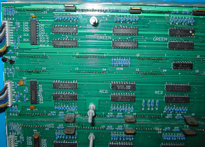
No need to be scared, pal. I can't provide immediate examples of what exact damage a shared resistor can cause, but I assure you using individual resistors would only yield better result. This is what I do, take a look at the attached picture and see how many resistors are used. This is the PCB for a dot-matrix LED screen. Each cathode has been connected to a resistor. This eliminates the possibility of cross interference between different LED's.