propeler
-
Posts
242 -
Joined
-
Last visited
Content Type
Profiles
Forums
Events
Everything posted by propeler
-
Honey, I developed FFB joystick (DIY)
propeler replied to propeler's topic in PC Hardware and Related Software
Well. This version is pretty much done and shipped to first beta tester. Waiting for his feedback for improvements -
Honey, I developed FFB joystick (DIY)
propeler replied to propeler's topic in PC Hardware and Related Software
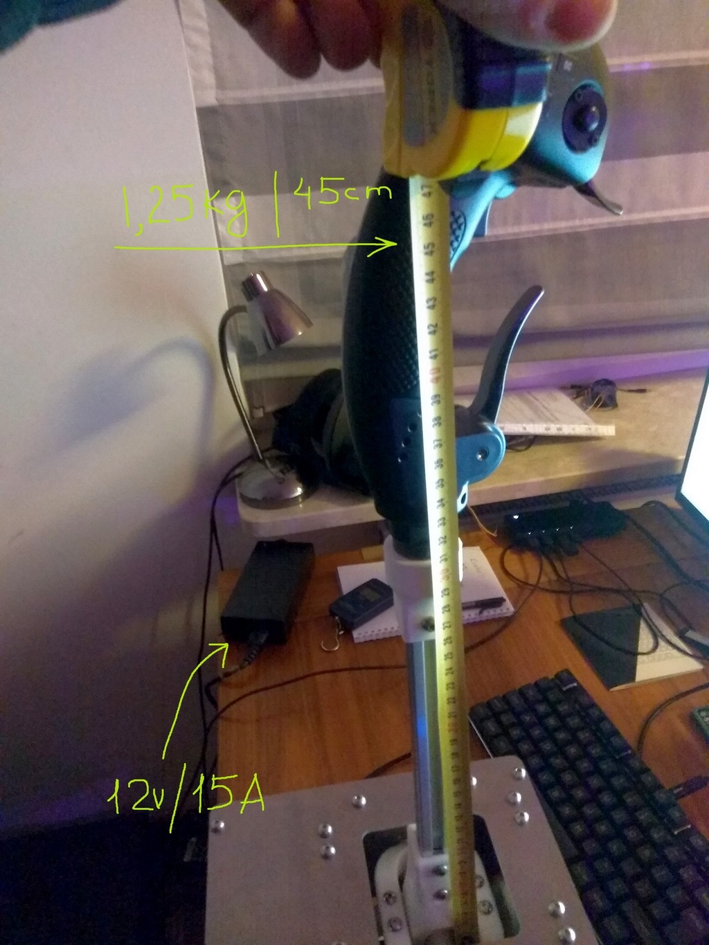
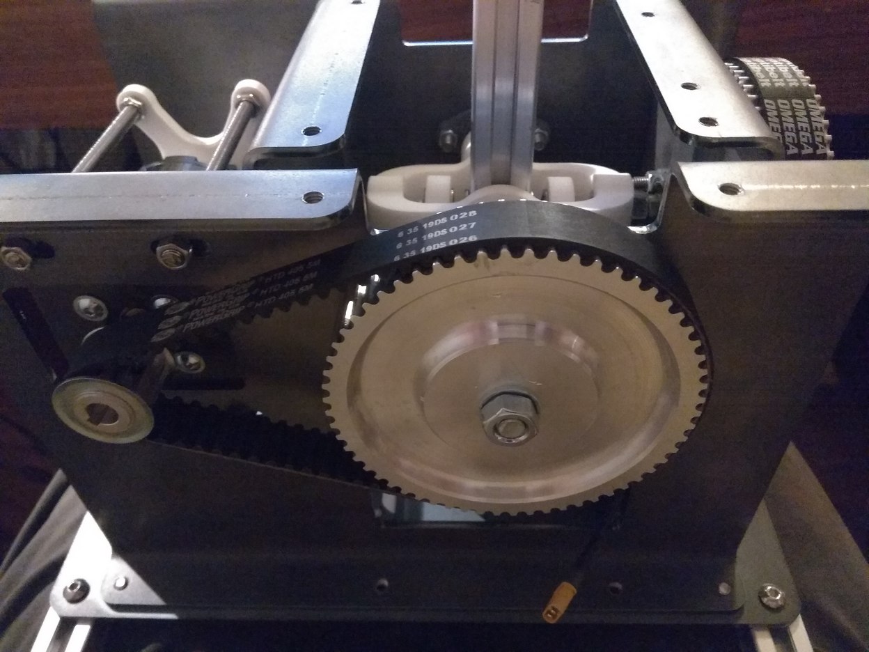
Measured static force which joystick can produce. At the point marked with arrow measured 1.25 kg with cheap china power supply 12V / 15A. After 5 minutes of static load motors and controller are barely warm. I think 30A power source can be used safely and it will give us nearly 2.5kg load at 45cm lever.
-
Honey, I developed FFB joystick (DIY)
propeler replied to propeler's topic in PC Hardware and Related Software
M ay be becaause of price? :) -
Honey, I developed FFB joystick (DIY)
propeler replied to propeler's topic in PC Hardware and Related Software
Thanks. I'm in Europe, so it will be easier to find it here :) -
Honey, I developed FFB joystick (DIY)
propeler replied to propeler's topic in PC Hardware and Related Software
Cut to my design. Was ordered in local laser cutting/bending service. -
Honey, I developed FFB joystick (DIY)
propeler replied to propeler's topic in PC Hardware and Related Software
I already have all effects working. Now I work on final touches - true FOC controll for motors and configuration interface for PC. -
Honey, I developed FFB joystick (DIY)
propeler replied to propeler's topic in PC Hardware and Related Software
I use standart STM32 HAL USB stack with descriptior from oficial PID documentation. For TM I already implemented reading TM devices. Simply need to found TM grip to test that everything works as intended( now only tested with TM ferrary wheel :) ) -
Honey, I developed FFB joystick (DIY)
propeler replied to propeler's topic in PC Hardware and Related Software
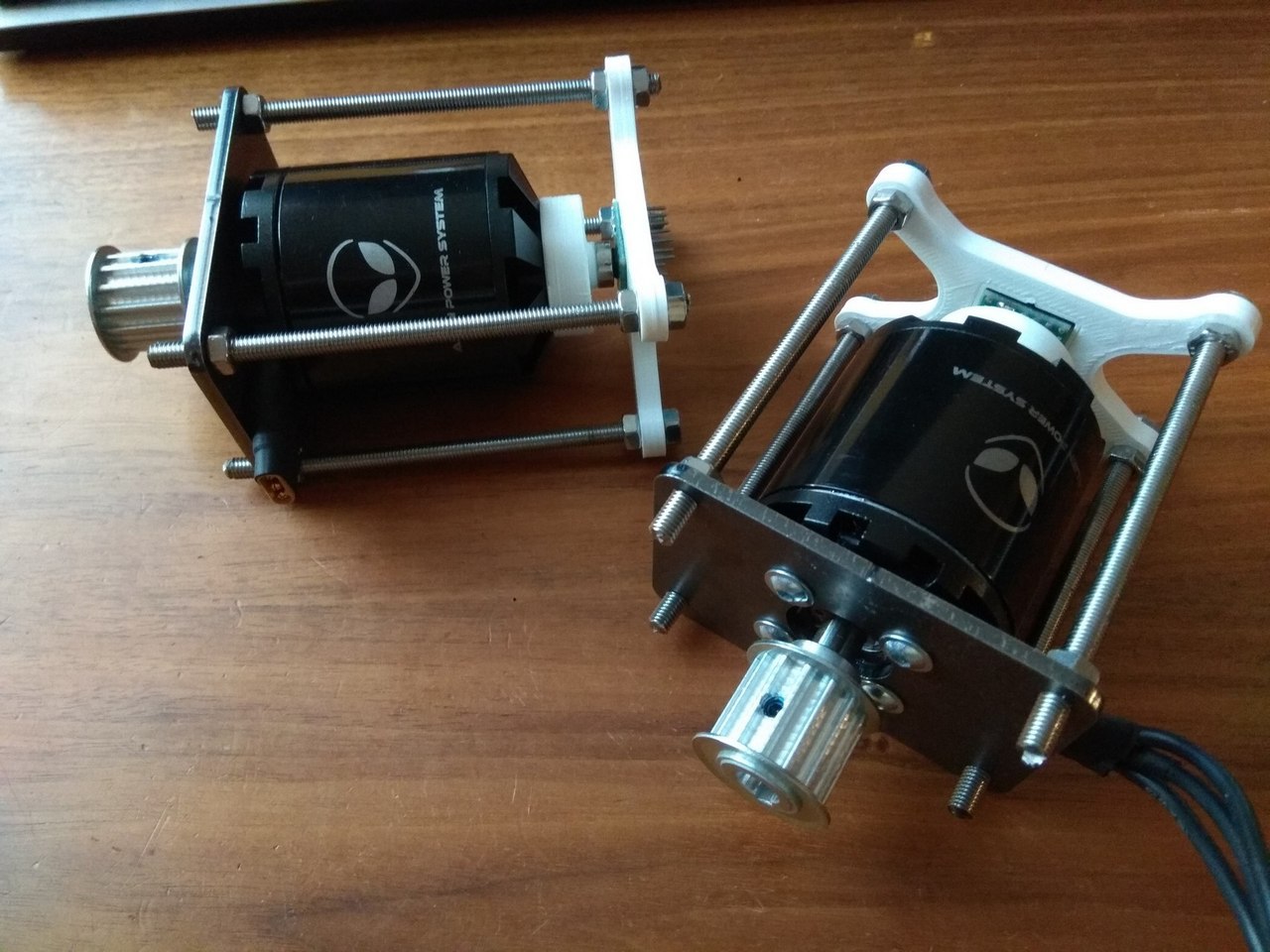
Metal parts finally arrived. I'm satisfied with this wariant:
-
Honey, I developed FFB joystick (DIY)
propeler replied to propeler's topic in PC Hardware and Related Software
AMS position sensor from AS504x series. I use SPI version of AS5047/AS5048 After I build and check that all parts fit without issues. Do not want to post not properly tested version :) -
Honey, I developed FFB joystick (DIY)
propeler replied to propeler's topic in PC Hardware and Related Software
Thanks, very motivating ;) Even less. 12v/20Amp -> 240W -
Honey, I developed FFB joystick (DIY)
propeler replied to propeler's topic in PC Hardware and Related Software
If it give you enough stiffness why not. You can try :) -
Honey, I developed FFB joystick (DIY)
propeler replied to propeler's topic in PC Hardware and Related Software
Do not have plan for grip production. There are disent choice of available grips. TM, VKB. I plan to support TM natively and solution fo mounting VKB but with usage of all VKB electronics. -
Honey, I developed FFB joystick (DIY)
propeler replied to propeler's topic in PC Hardware and Related Software
Oh.. It is not only about how big motor look like from outside. Depends much how motor constructed. Number and type of magnets, number of poles, size of stator, winding wire, type and turn count, type ofmotor(inrunner\outrunner). It gives very different kV and Amp rating for motor -> so different possible torque. -
Honey, I developed FFB joystick (DIY)
propeler replied to propeler's topic in PC Hardware and Related Software
Depends on targeted dimensions of the whole unit. Needs metal gimbal with different mechanical scheme for such high torque. But it is not impossible. -
Honey, I developed FFB joystick (DIY)
propeler replied to propeler's topic in PC Hardware and Related Software
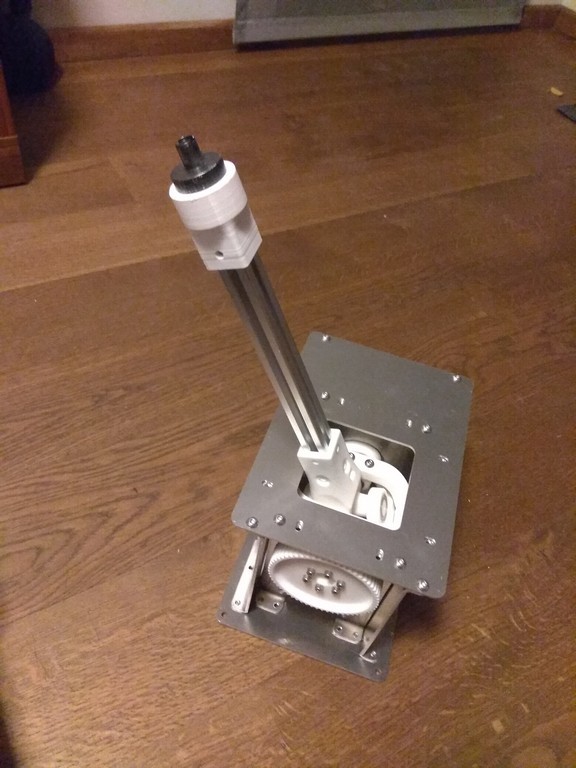
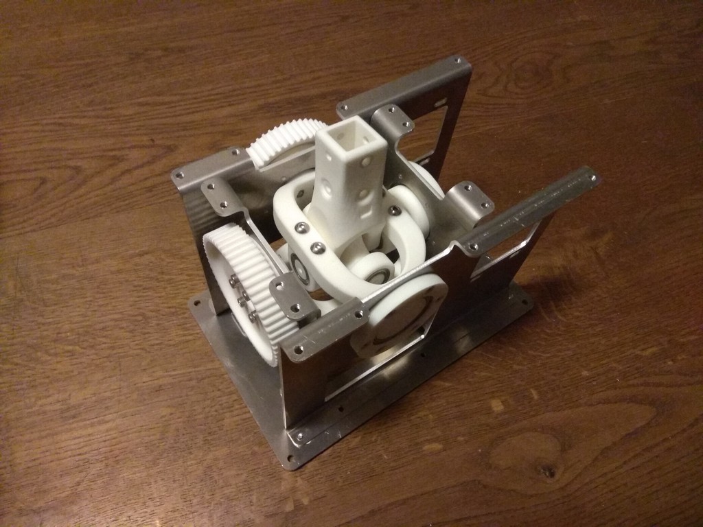
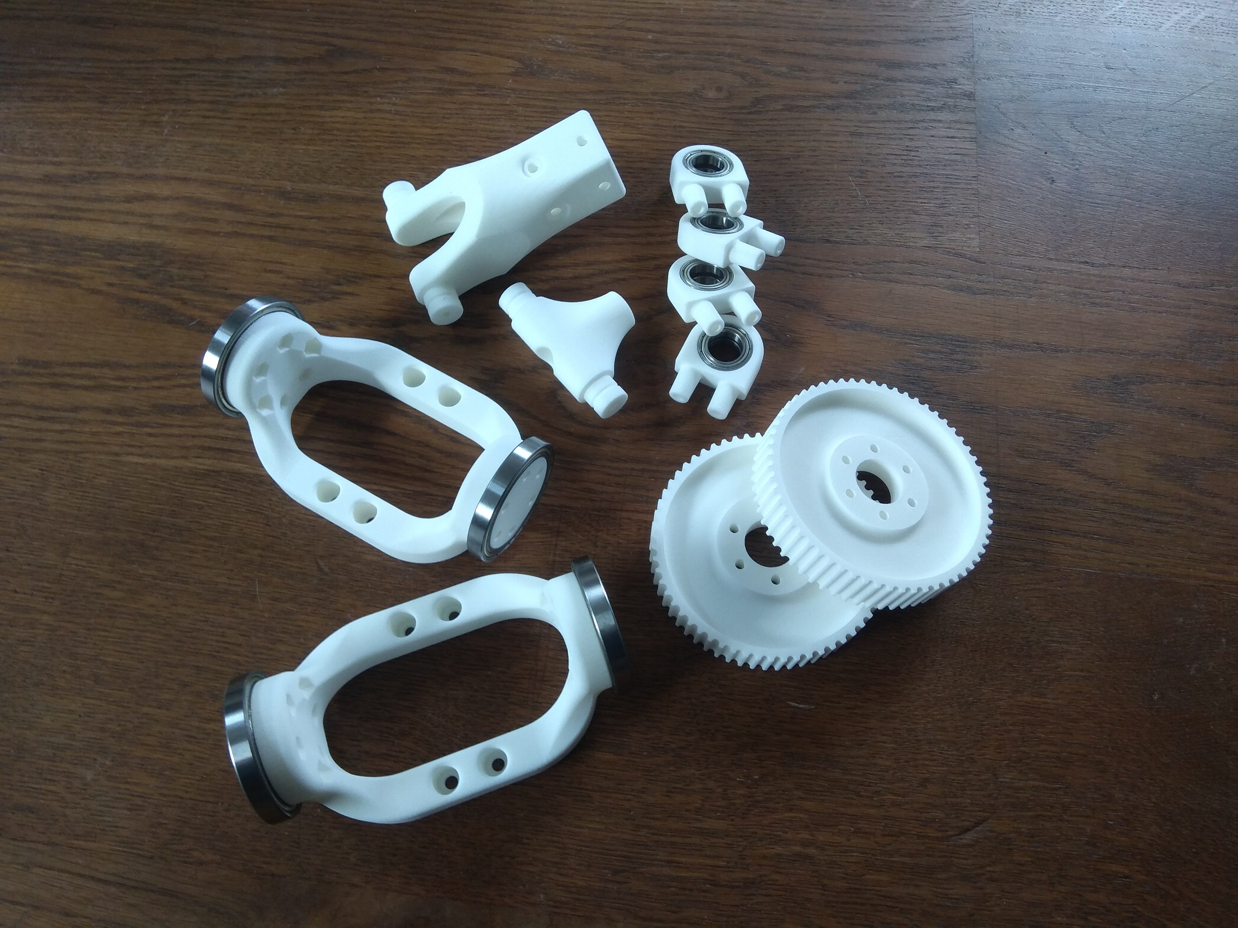
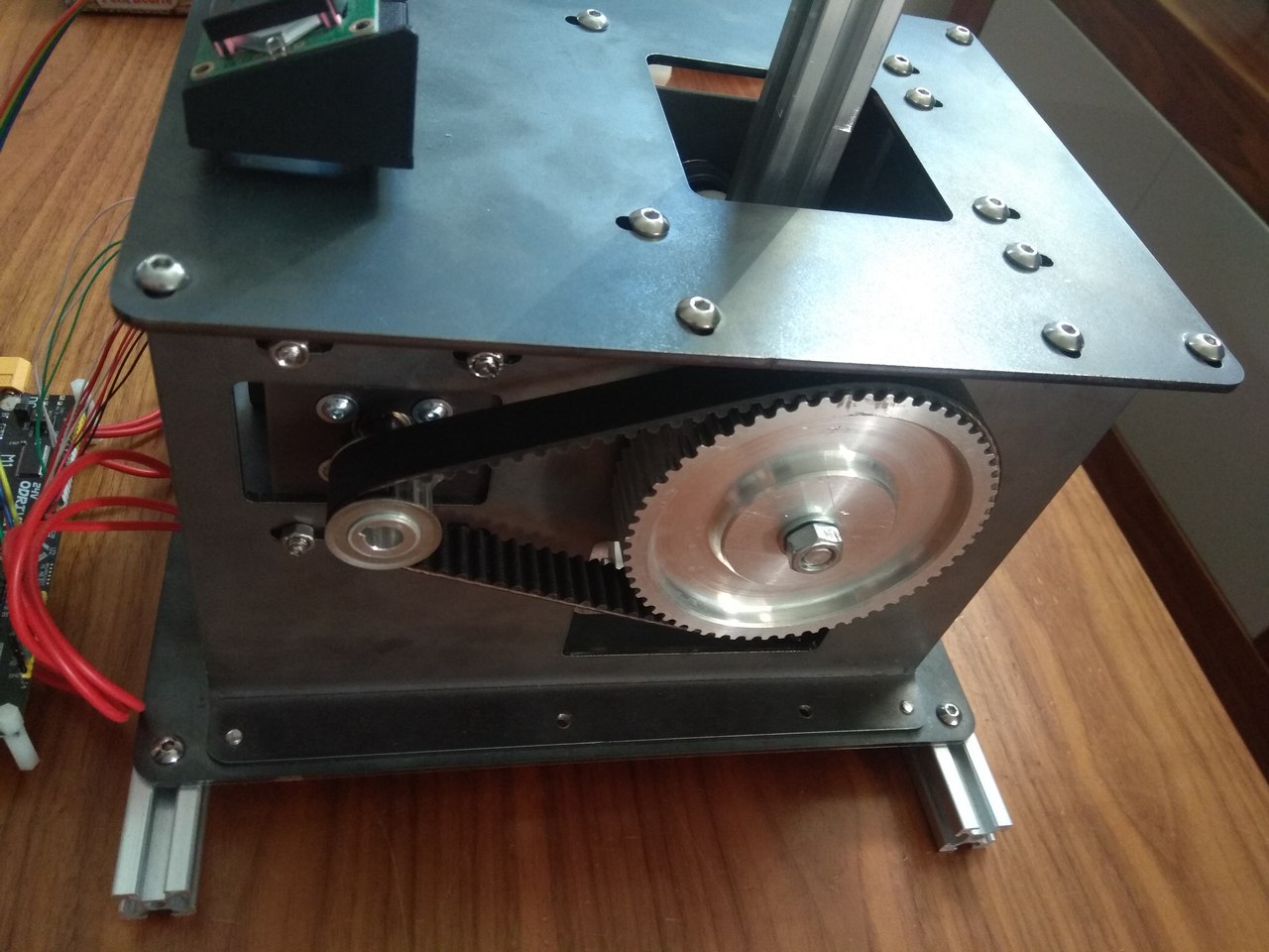
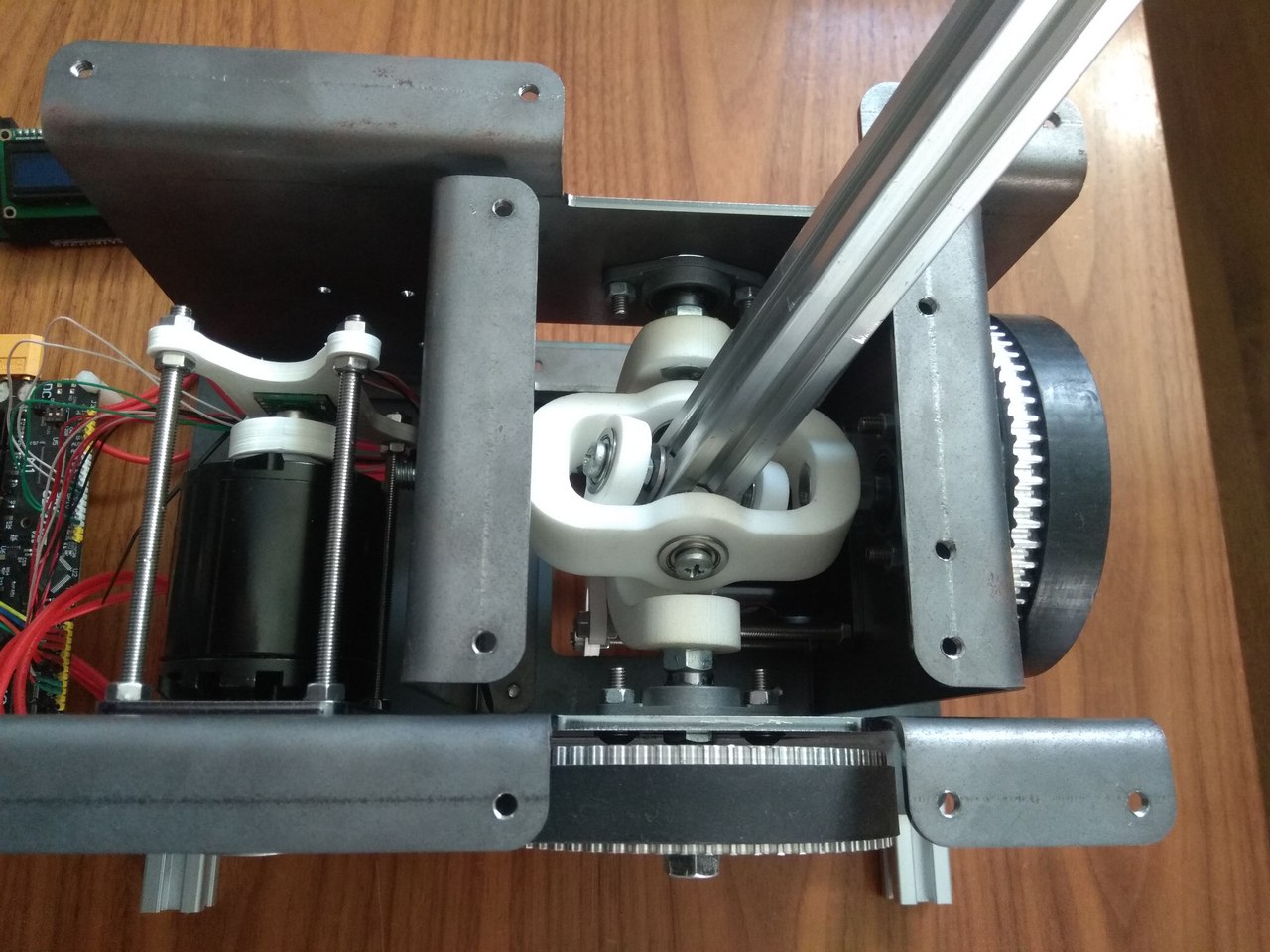
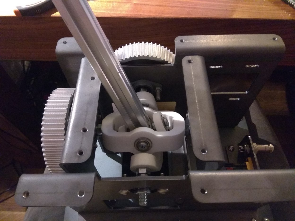
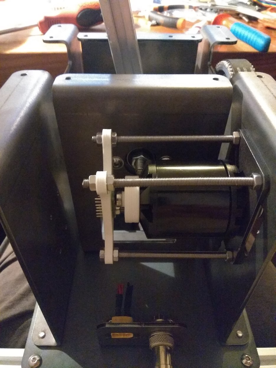
Update for the gimbal set. Inspired by MS FFB one. Improved stiffness. All moving joins are on massive ball bearings. Hope it will be final iteration for gimbal.
-
Honey, I developed FFB joystick (DIY)
propeler replied to propeler's topic in PC Hardware and Related Software
I plan to open CAD files for it when I will be sure that everythig is working togetther and anyone who is interested in it can build it. And will build it for those who would like to have ready for use solution :) -
Honey, I developed FFB joystick (DIY)
propeler replied to propeler's topic in PC Hardware and Related Software
Do you think it is too much for the motors? :) Those motors are rated for 55A max. 20A for them is a super mild condition. Taking into account that such current will be at max deflection only. oH.. It is another story. Building something is my hobby, so I spend time for it not on regular basis. When I started it I was total zero in electronics. Now I know a lot about power electronics, microcontrolers, USB protocol, PID algorythms, FOC motor controll, PCB prototyping and so on. Reading about all of that things took most of the invested time. But those things are simply interesting for me :) -
Honey, I developed FFB joystick (DIY)
propeler replied to propeler's topic in PC Hardware and Related Software
If you mean trim which is assigned to T button by default - yes. it works. Needs position smoothing on button press, but works. -
Honey, I developed FFB joystick (DIY)
propeler replied to propeler's topic in PC Hardware and Related Software
Did not make exact calculations, because there was some iterations thrown away into trash busket :) But I think something around 650$ in total. Depends whery much on price of 3d printing and cutting/bending metal parts. There is another improved version of gimbal in printing service now. Will make precise calculations when it arrive and will be tested. -
Finally, it is time to introduce my FFB joystick prototype! I spent a lot of time and learned a lot of new stuff when work on it. So here what is already implemented: - Works as standard USB FFB device, understands standard FFB protocol. No drivers. No plugins. - Supports spring, constant, ramp an periodic effects. - Custom firmware for STM32 microcontroller family. - Currently ODrive controller is used as the hardware, but custom made, much more affordable controller is on its way from manufacturer. - Uses affordable hobby grade brushless motors. - Nearly 8Nm of torque planned with 20A of current per motor. - Smooth operation almost without noticeable cogging. In plans: - Support for Thrustmaster grips. - PC software for interactive effect gains tuning. - Improvements :) And a little bit of media :joystick:
- 492 replies
-
- 12
-

-

-
Force Feedback Joystick Coming soon
propeler replied to FoxHoundcn's topic in PC Hardware and Related Software
Hopefully :music_whistling: Mechanical part is ready. Firmware is on final approach...
-
Tired to wait for VKB throttle. So I built my own. Grip project is available for free use and modification. Github repo have both original Solidworks files and STLs ready for printing. Enjoy. https://github.com/o-devices/throttle-quadrant
-
Force Feedback Joystick Coming soon
propeler replied to FoxHoundcn's topic in PC Hardware and Related Software
That's why I say: Let's wait when someone make real review)) -
Force Feedback Joystick Coming soon
propeler replied to FoxHoundcn's topic in PC Hardware and Related Software
It is simple math. If you have 4.2 Nm torque on Off-axis 10cm you will get 4.2 / 100 * 10 = 42N -> 4.2 kg -
Force Feedback Joystick Coming soon
propeler replied to FoxHoundcn's topic in PC Hardware and Related Software
Yep. Something like this. But only real tests will tell us the truth :) I assume that this base will be ok for table-top or side-stick usage without any extensions and with light grip.