lesthegrngo
-
Posts
1245 -
Joined
-
Last visited
Content Type
Profiles
Forums
Events
Everything posted by lesthegrngo
-
Ok, I have bdfconv in my D:\Downloads folder, and I also have a copy of DSEG14Classic-Bold-54.bdf in that same folder I have opened CMD, typed bdfconv, and the list of the options appears. I typed bdfconv f 1 -n SEG14.c DESG14Classic-Bold-54.bdf and pressed enter. Nothing happens, no file is generated, although neither are any error messages. Have I got the syntax correct? I also tried bdfconv f 1 -m "1-38" -n SEG14.c DESG14Classic-Bold-54.bdf, with no results ****EDIT*** Got it - forgot to specify the -o output file Cheers Les
-
I just tried that convertbdf, but the 'white area for for choose a file' is nowhere to be seen - is there any special extension that I need to run this? ***EDIT*** I resolved the "no module named PIL" error, after watching a load of videos on how to correct it on Youtube - shame most of them forget to metion the syntax errors that will keep on appearing unless you type "exit()", that would have saved me some head bashing. However when I ran the python code I got a "can only concatenate str (not "int") to str" message, which when I look at the solution makes me want to go and drown myself. I give up on python...... Cheers Les
-
Guys, I have tried to find the cause and have managed through the Python console to get this "= RESTART: D:\Downloads\fonts-DSEG_v046\fonts-DSEG_v046\DSEG14-Classic\bdf_to_h.py Traceback (most recent call last): File "D:\Downloads\fonts-DSEG_v046\fonts-DSEG_v046\DSEG14-Classic\bdf_to_h.py", line 3, in <module> from PIL import Image ModuleNotFoundError: No module named 'PIL'" So it looks like there is a missing module, but I cannot work out how to get that missing module back in in Win 10 installations. I used this page to try https://www.pythonpool.com/solved-no-module-named-pil/ but nothing is reflected in my installation - I just get invalid syntax messages I tried looking at something called Pixelmatics in Github, but have absolutely no idea how to use that either Can anyone who is familiar with this help? Cheers Les
-
The 'do....while' loop has fixed it. I can now render the output over the whole display On to make the bespoke font ***EDIT*** Ok, this is where my lack of in-depth understanding of things like Python and C let me down. I was able to convert the font to .dbf, I installed python, I copied the bdf_to_h.py and bdf_to_combined.py into the folder with the dbf font in it and double-clicked on the .py files per the instructions below. "3) Now double-click either of these two files, depending on what you want: - `bdf_to_h.py` - this will create a seperate .h file for each BDF file - `bdf_to_h_combined.py` - all BDF fonts with the same name combined into the same .h file (with multiple sizes) " Unfortunately, nothing happens other than a brief opening of the CMD window, no .h file is generated. Any Ideas? Cheers Les
-
I am going to try and use the ‘do… while’ loop, and the U8X8 variations to see if that helps, as all I am trying to do is display text hopefully it will resolve this Les
-
The puzzling thing is the simple sketch is also only using half the display buffer, but can be shown anywhere on the display, so the behaviour is not the same. Both sketches have this line U8G2_SH1122_256X64_2_4W_SW_SPI u8g2(U8G2_R0, /* clock=*/ 12, /* data=*/ 11, /* cs=*/ 9, /* dc=*/ 10, /* reset=*/ 15); but only the DCS Bios sketch limits where you can put the text Les
-
Thanks guys - I was looking at doing the fonts myself, they are available as files for use in things like inkscape so that may shorten the process I am still battling the OLED, if I use a simple sketch like the one above, the whole display is available, however once I put a simple BIOS sketch in it, anything below a third of the screen height gets blanked. Not sure what is going on Les
-
Does anyone know if there are any u8g2 fonts that resemble 14 segment LCD displays? Cheers Les
-
Well, I managed to fix it myself. It seems that the OLED I have is fussy which pins it uses, when I changed over to use pins 9 through 12 for the CS, DC, SDA and SLC, it just worked Here's the code for reference #include <SPI.h> #include <Arduino.h> #include <U8g2lib.h> #include <Wire.h> /*#define PIN_MOSI 18 #define PIN_CLK 19 #define PIN_DC 17 #define PIN_CS 16 #define PIN_RST 13*/ U8G2_SH1122_256X64_2_4W_SW_SPI u8g2(U8G2_R0, /* clock=*/ 12, /* data=*/ 11, /* cs=*/ 9, /* dc=*/ 10, /* reset=*/ 15); // Enable U8G2_16BIT in u8g2.h void setup(void) { u8g2.begin(); u8g2.firstPage(); do { u8g2.clearBuffer(); u8g2.setFont(u8g2_font_ncenB08_tr); u8g2.drawStr(180, 20, "hello"); // 0 left, 0 top bottom appx 100 } while(u8g2.nextPage()); delay(1000); } void loop() { } So you cannot use the pins that are used by I2C 4 pin connections on SPI devices apparently Cheers Les
-
Thanks for the input I tried your suggestion with the following simple code with three variations, but it still hasn't worked. #include <SPI.h> #include <Arduino.h> #include <U8g2lib.h> #include <Wire.h> #define PIN_MOSI 18 #define PIN_CLK 19 #define PIN_DC 17 #define PIN_CS 16 #define PIN_RST 13 //U8G2_SH1122_256X64_2_HW_I2C u8g2(U8G2_R3, PIN_CS, PIN_DC, PIN_RST); // All Boards without Reset of the Display R3 refers to 270 deg text rotation U8G2_SH1106_128X64_NONAME_2_4W_HW_SPI u8g2(U8G2_R0,/* cs=*/ 16, /* dc=*/ 17, /* reset=*/ 13); //U8G2_SH1122_256X64_1_4W_SW_SPI u8g2(U8G2_R3, 19, 18, 16, 17, 13); void setup(void) { u8g2.begin(); u8g2.clearBuffer(); u8g2.setFont(u8g2_font_ncenB08_tr); u8g2.drawStr(20, 50, "hello"); // 0 left, 0 top bottom appx 100 u8g2.sendBuffer(); delay(1000); } void loop() { } I am now going for the least palatable option, I am going to ask the Arduino forum to see if someone has a solution, or whether they will just look down on me as usual! Cheers Les
-
Thanks Vinc - This is a 328 Arduino Nano. I do have a board I can use, but it will complicate the process due to not being able to use RS485, and so having to port USB to it. For the 'F' versus '2', I thought that was only half the available display buffer rather than full - I have used it to reduce the size of sketches on my arduinos to get U8G2 sketches onto 168 devices, and they work fine, although none are fast changing displays I do have a spare Uno I can try, but wonder if the issue will be the same Les
-
Hi all I have been at this for a while now, trying different codes but am having to hold my hands up. I have one of these https://www.ebay.com/itm/125463195502?var=426488515340 which in spite of the description saying a 4 wire SPI connection is actually a 7 pin connector Despite defining the correct pins, and the sketch compiling and loading OK nothing is being displayed #define DCSBIOS_DEFAULT_SERIAL #include <DcsBios.h> #include <Arduino.h> #include <U8g2lib.h> #include <Wire.h> #define PIN_MOSI 18 #define PIN_CLK 19 #define PIN_DC 17 #define PIN_CS 16 #define PIN_RST 13 U8G2_SH1122_256X64_2_4W_HW_SPI u8g2(U8G2_R3, PIN_SPI_SS, PIN_DC, PIN_RST); // All Boards without Reset of the Display R3 refers to 270 deg text rotation void setup(void) { u8g2.begin(); DcsBios::setup(); } unsigned int vhfamFreq3 = 0; void onVhfamFreq3Change(unsigned int newValue) { vhfamFreq3 = newValue; u8g2.clearBuffer(); //u8g2.setFont(u8g2_font_logisoso38_tr); u8g2.setFont(u8g2_font_ncenB08_tr); u8g2.drawStr(20, 50, vhfamFreq3); // 0 left, 0 top bottom appx 100 u8g2.sendBuffer(); delay(1000); } DcsBios::IntegerBuffer vhfamFreq3Buffer(0x118e, 0x0f00, 8, onVhfamFreq3Change); void loop() { DcsBios::loop(); } I suspect that the problem lies in the board setup line " U8G2_SH1122_256X64_2_4W_HW_SPI u8g2(U8G2_R3, PIN_SPI_SS, PIN_DC, PIN_RST);" I tried " U8G2_SH1122_256X64_2_HW_I2C u8g2(U8G2_R3, PIN_SPI_SS, PIN_DC, PIN_RST);" but that doesn't work either. Looking at the library online I can't see any more relevant ones. Can anyone see the issue? Cheers Les
-
Take a look here https://docs.arduino.cc/built-in-examples/basics/AnalogReadSerial
-
I don't believe that you can have 'selJettBtn' as both a switch and an LED, you have to have different terms or references for each Cheers Les
-
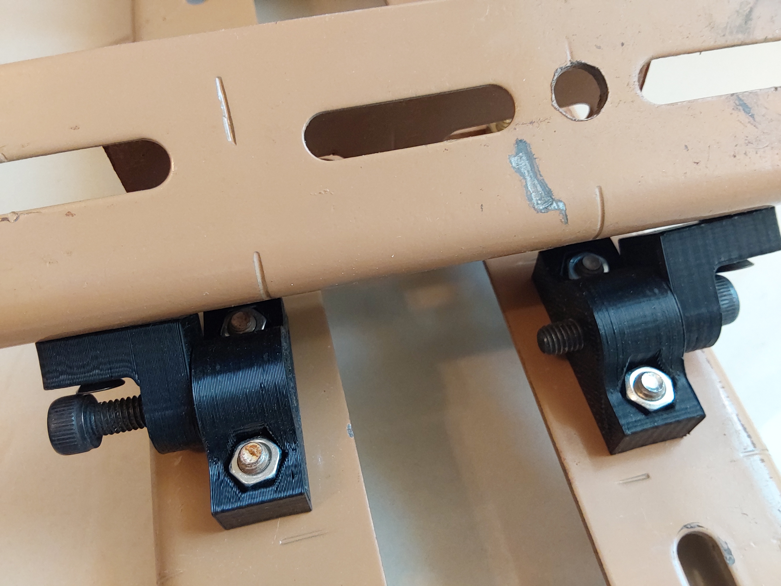
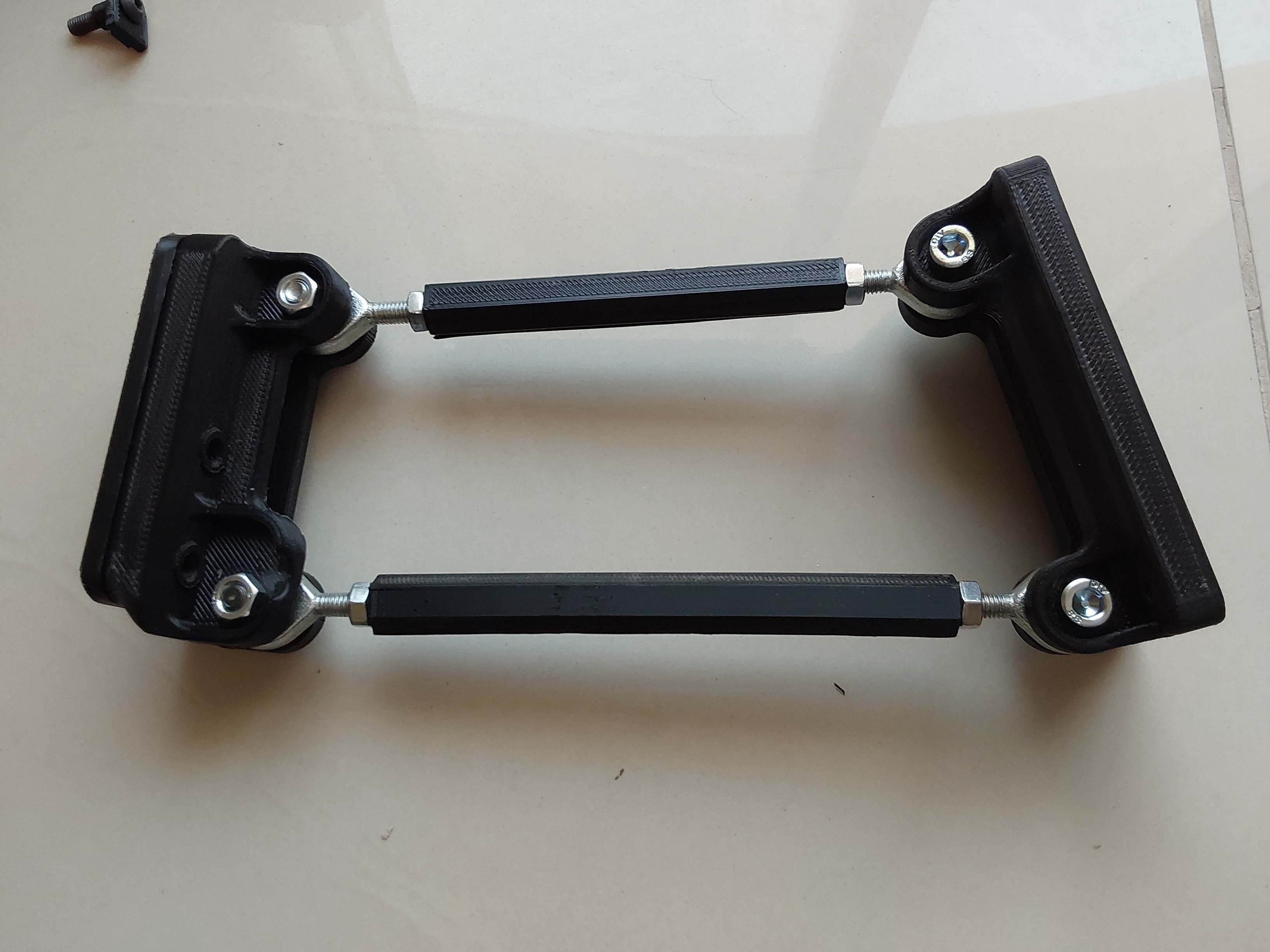
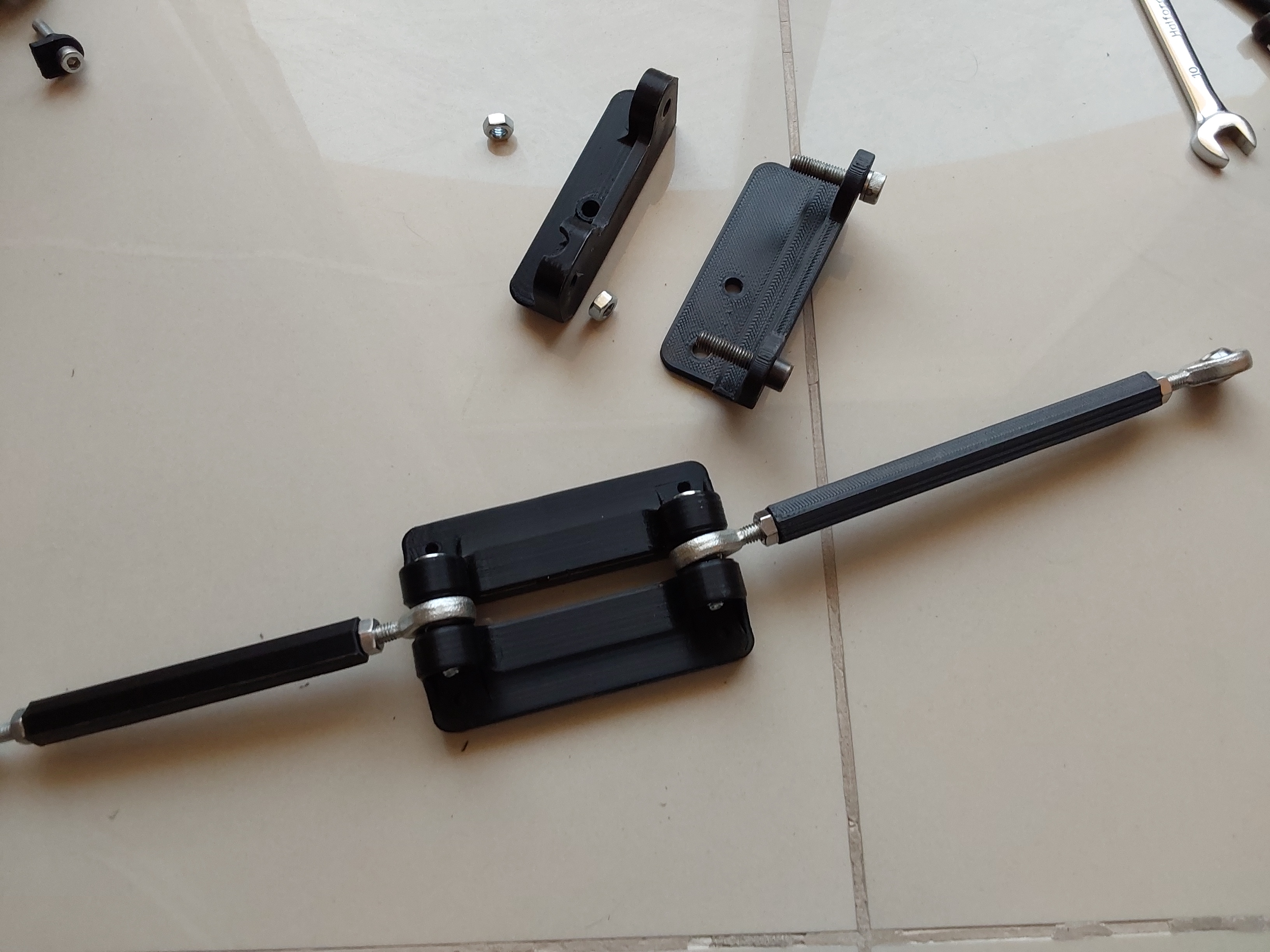
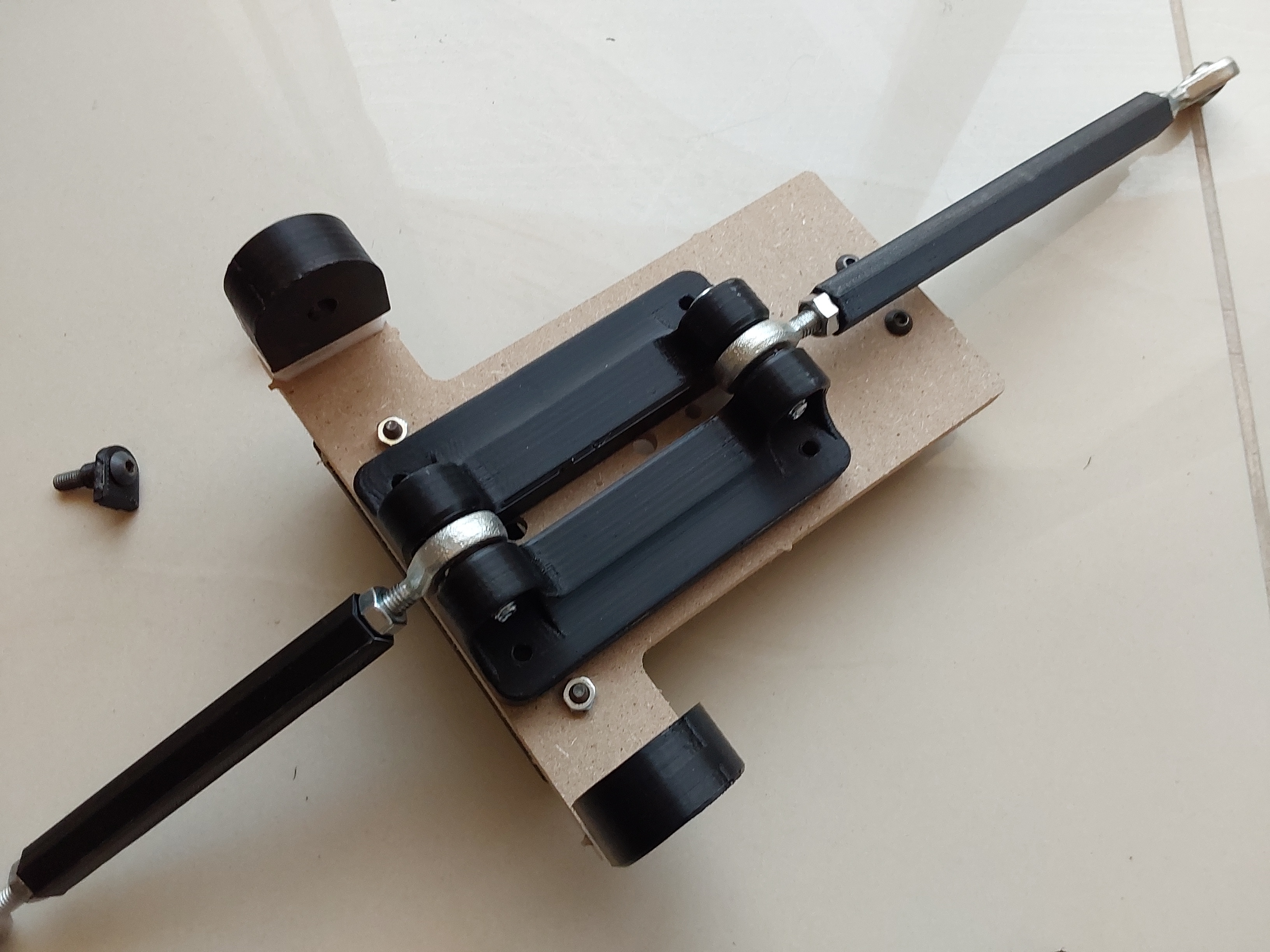
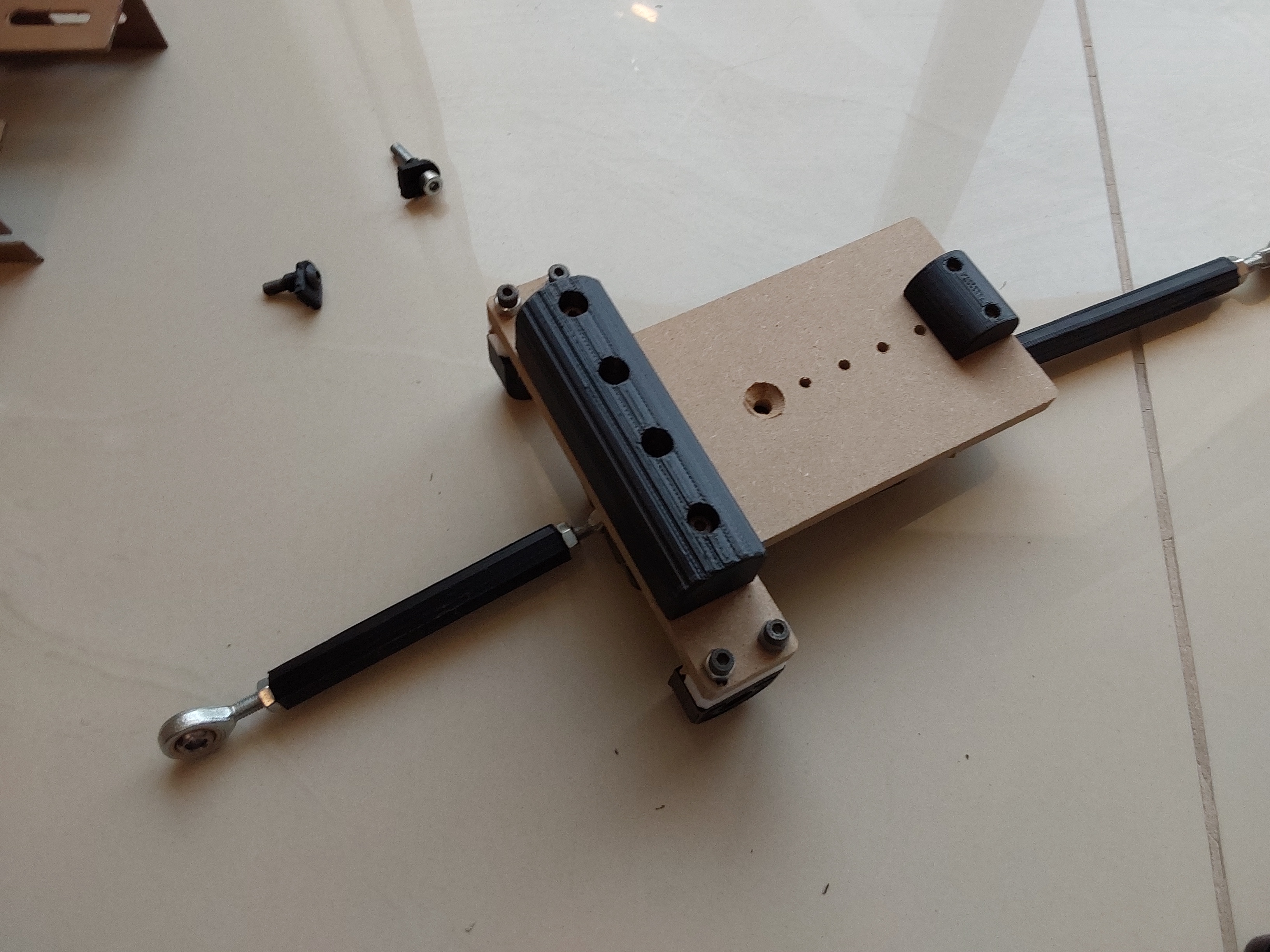
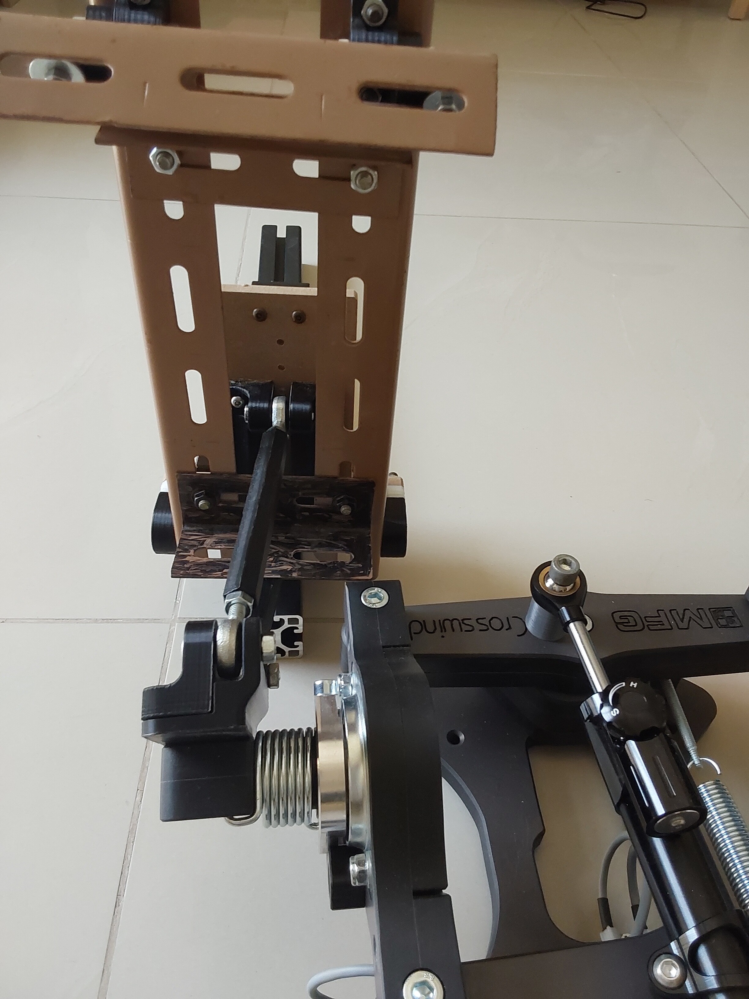
Here are some better pictures of some of the parts These are the push rods, MFG attachment on the left, pedal attachment on the right. The longer rod goes to the top for the toe brake actuation The upper stirrup pivot trunnions, the larger block houses the bearing. The individual parts for the parallelogram link; left to right at the bottom, rudder push rod, two part rod end saddle for the back of the pedal, toe brake push rod At the top is the rod end adapter saddle for the MFG base The rear of the pedal showing the saddle attached, and the pivot bearing housings Front of the pedal, with the main rudder push block on the left and the toe brake push block on the right. All these parts are just for proof of concept , and once I have correctly positioned everything better designs will follow Les

-
would more photos help....?!! Les
-
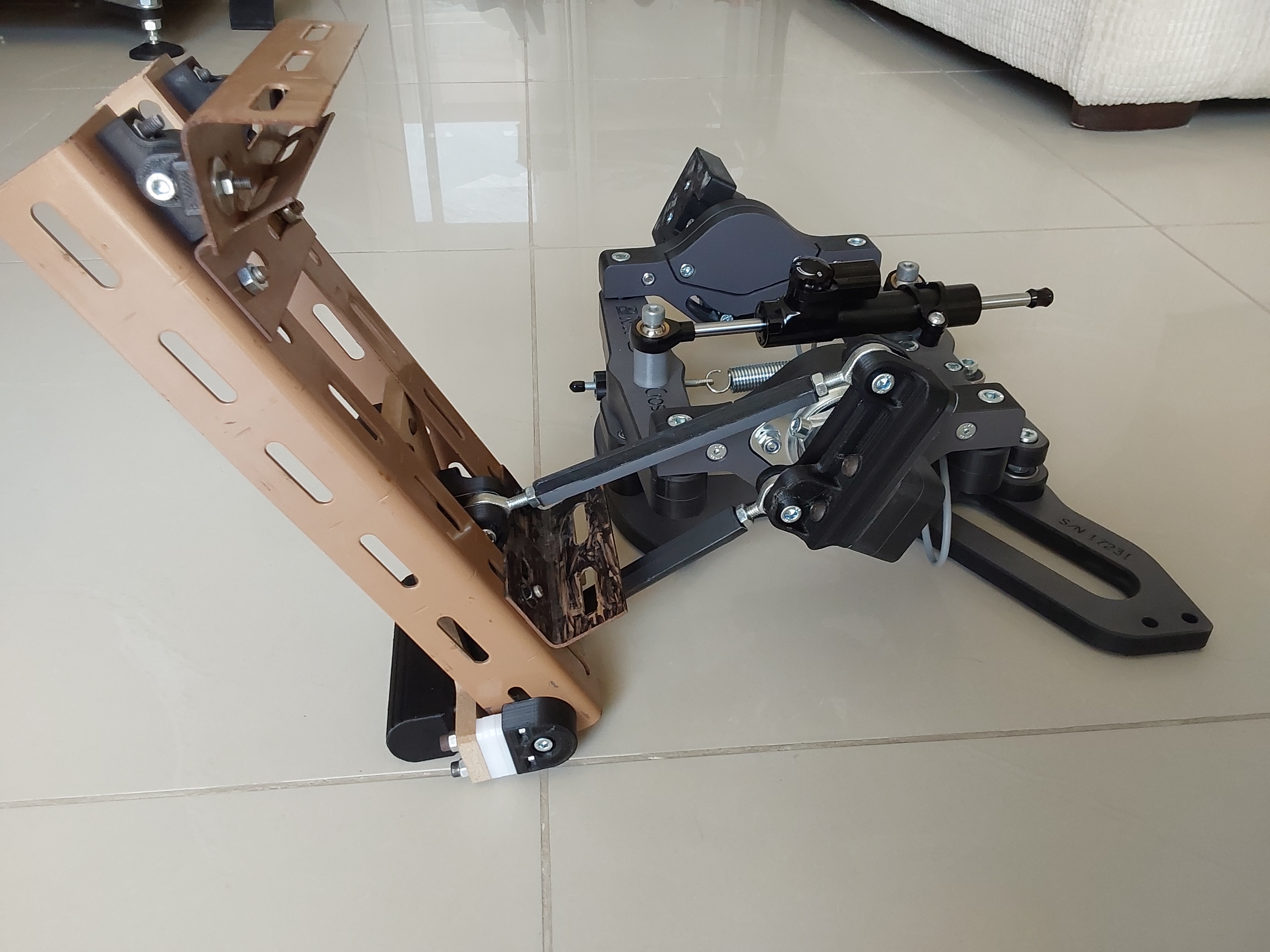
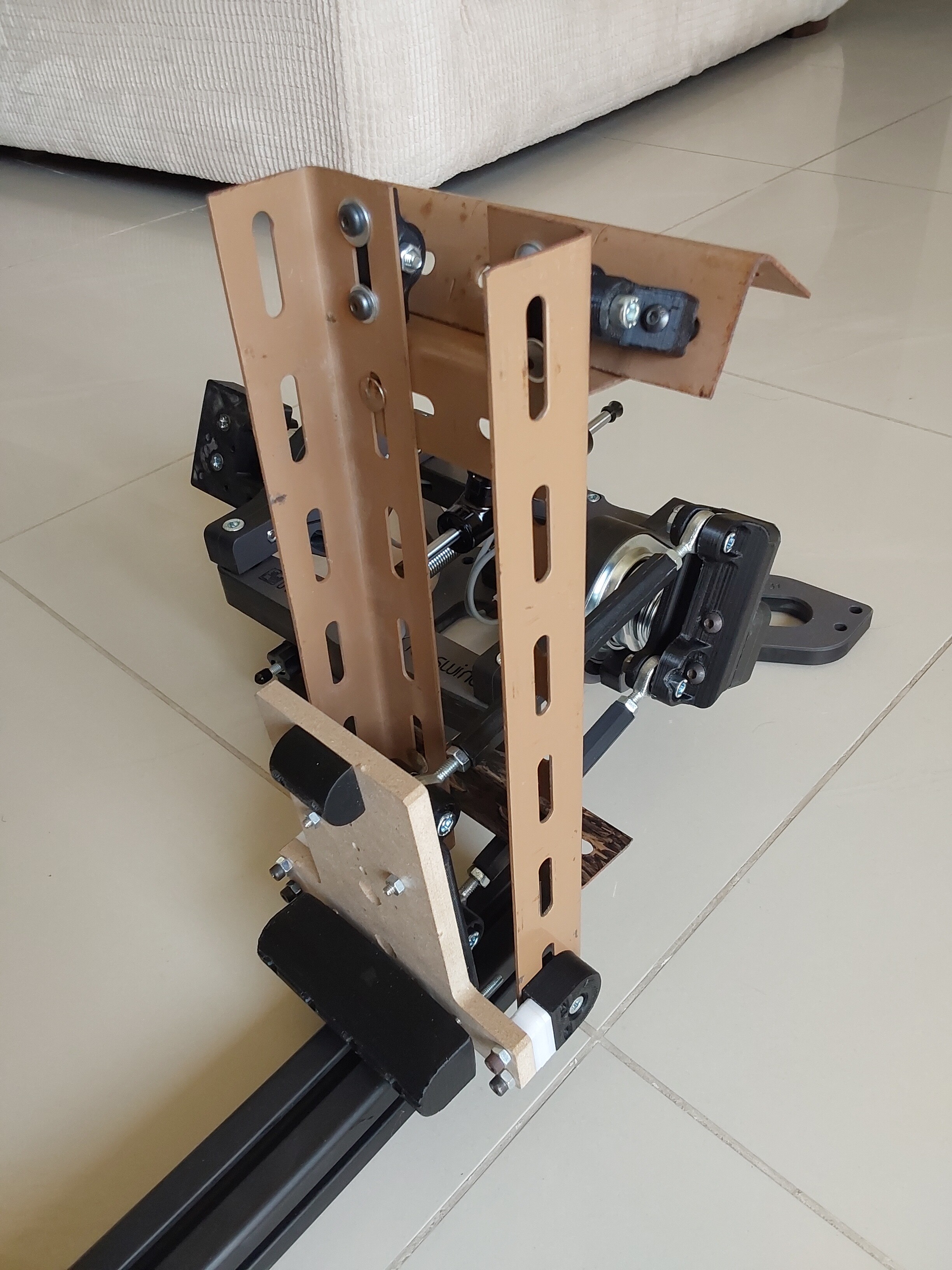
True to form, now that I have the MFG Crosswind pedals I can't help myself - I had to see if I could make some pendulum pedals to work with them. As a result of some initial test parts, I have come up with the pedal arrangement in the pictures below. Essentially there is a stirrup (the brown Dexion structure) which is pivoted at the top, and then there is an MDF pedal which is pivoted at the bottom of the stirrup. A 3D printed twin point rod end bracket is fixed to the back of the pedal, which has 3D printed toe brake and lower foot rest bumps attached. A matching twin point rod end bracket is made and fitted to the MFG pedal pad in place of the original pedal. Finishing off the assembly are the two parallelogram linkages with the rod ends fitted. All the pivot points are 3D printed trunnions with 6mm ID ball bearings. The intention is to make sure that all the pivots are good quality so that they do not affect the pedal movement or induce any unwanted geometry changes. As a result one of the design considerations which can't be seen from the pictures below is that the the pedal fore and aft movement is essentially on the same horizontal plane as the MFG pedal pivot axis. This (hopefully) will ensure that any fore and aft movement of the pedal is translated into a linear movement by the lower push rod, but that rotating the pedal using the toe brake will act above the MFG pedal pivot axis and so act only to rotate the pedal with no fore and aft movement. So as you can see this is all cobbled together with very adjustable materials so that I can alter angles, distances and pivot points before finally settling on sizes for a better aluminium structure. All that remains now is for me to install them solidly in my rig in such a way that the angles and movements can be tested without any flex or looseness affecting how the pedals move or actuate the MFG pedal base. That will allow me to determine the final sizes and geometry I made some 3D models of most of the MFG pedal base to allow me to model the movement in CAD, and I will probably make those available on GrabCad, but please note that I am deliberately not modelling certain parts and am using reduced accuracy on other parts as I do not want to undermine MFG's proprietary info. As a result they are good to see if the pedals will fit in your rig, but not much more. For the other self designed parts, I will happily share those. As soon as I have been able to fit them into my rig I will report back on whether or not it is a workable project. Cheers Les
-
Should we have a 3D print file repository as a sticky?
lesthegrngo replied to Lace's topic in Home Cockpits
I've been using GrabCad for parts I've made, and just linked them in posts where I showed them. Happy to put links in a dedicated thread though Les -
MFG Crosswind pedals - initial thoughts
lesthegrngo replied to lesthegrngo's topic in PC Hardware and Related Software
I am knocking together some pendulum pedals to work with the Corsswind pedal base. They lend themselves to it due to their adjustability, meaning that you don't have to modify the pedals themselves, simply make adapters. Once I have the mock ups I will post them on here as they are not complicated Cheers Les -
yeah, that's the one - so many models, so few brain cells.....! Les
-
Thanks! Les
-
Hi again, I have ordered the Creality Ender S3 Plus and some reels of Eryone PETG. It's going to take a while to get here (mid May probably) but I will use that time to knock up some designs to print out when it finally gets here. I went for it due to the big build size, and hopefully it will let me make single piece parts for the coaming, and one piece pedal plates to go on my MFG Crosswind pedal base I'll have to mess around with it to see what works and what doesn't, it will be interesting to see what I am able to do cheers Les
-
Vinc's three gauges above work perfectly, I have made them using his code myself. However his first post set out the hardware and from personal experience I can attest to the fact that you are best going with the devices specified to avoid issues. Thanks for all the help and for posting Vinc! Les
-
Glad you found it, but it also goes to show that it is too easy to go down rabbit holes chasing complicated solutions what the problem is a simple one. I've done it, chasing the problem by swapping chips, nanos, steppers, you name it... only to find it was a duPont jumper wire or a USB cable. Always try replacement cables first, and try to log what you change because it's too easy to lose track. One trap I fell into was to use an Ohmmeter to check continuity on a cable, which showed it was OK while I was holding it down, only for the problem to reappear what the cable was installed. By holding the cable down to check it, I was unwittingly making the broken cable make contact, which then opened up when I let it go. As a result, I try to check the cables in the loose state, or swap the cable out if there is one I can A last word about USB cables, at least from my experience; some USB cables are better than others, some are good for charging, others not, and the same for data. Lastly, the one that really killed me for about 9 months was an issue with the PC itself. My RS485 network just stopped working, and nothing I did changed it. It never occurred to me that it might be the PC used to program the arduinos until a chance comment from someone on this forum. Using another PC which happened to have a later version of the Arduino IDE installed instantly cured the issue. The moral is, when troubleshooting don't discount anything, but always start with the basics. And be methodical. Cheers Les
-
Thanks, certainly a good point. Since getting my resin printer, I have to confess that I'd sort of turned away from FDM printing, not least because because of the quality of the resin prints. But as always it was a combination of factors. One was mentioned above, but another big factor was the build plate size. The Lulzbot Mini was not cheap when I bought it, but the main reason for selecting it was the bed self levelling capability which singled it out amongst its erstwhile peers; unfortunately it also came with a 152 x 152mm build plate which meant anything large was out of the question. As it predated my sim build it wasn't an issue, but as I went along with stuff I began to run the small part limitation and that anything bigger would be compromised by being made in sections. My answer to that was alternative manufacturing techniques. Now I'm looking for some more complicated parts that would be problematic with my CNC machines due to the multi-part nature that would be required, I'm coming full circle back to the FDM method as being the best compromise. But I know my machine is not capable of it, so I looked today at what may suit. All I can say is that in the intervening 6 years things have moved on immensely, and I haven't kept up. Well, things are really different now. For a third of the price (if not less) I can get a printer that is far far better, but with a 50% bigger build plate in each direction, has auto build levelling, a build plate that you can actually get the #*&%^^£ parts off when finished without breaking the build plate or PEI layer.... plus a load of other advances. Time I moved forward, I think..... Les