Snakedoc
-
Posts
305 -
Joined
-
Last visited
Content Type
Profiles
Forums
Events
Everything posted by Snakedoc
-
 As per title, anytime an asymmetric loadout is used, the aircraft doesn't taxi on the ground straight requiring constant rudder adjustments. At low speed the parasite drag generated by any stores is virtually none so it shouldn't have any impact on the yaw moment This is evident also if any pod is loaded on the left or right hardpoints but not as much like with different weapons. I've attached 2 tracks. One with a clean aircraft which taxi straight with no rudder inputs, a second one with an asymmetric loadout to highlight the issue. not sure if it's related to an old bug which was fixed in DCS 2.9.5.55300 DCS: F-16C Viper by Eagle Dynamics Fixed: Wheel friction imbalance. F16 asymmetric loadout bug during taxi.trk F16 no bug on taxi without asymmetric loadout.trk
 -
FPS drops and mouse movement causing stutter
Snakedoc replied to ExGreyFox's topic in Game Performance Bugs
experiencing also a noticeable loss of performance since last hotfix (2.9.6.58056). Disabling Tacview, reducing mouse polling rate to 500dpi as suggested & ALT+tab once in a while restores some of the performance loss but still not the same level as pre-patch -
experiencing also a noticeable loss of performance since last hotfix (2.9.6.58056). Disabling Tacview, reducing mouse polling rate to 500dpi as suggested & ALT+tab once in a while restores some of the performance loss but still not the same level as pre-patch
-
nullusername: <Snakedoc> 1. Weasels over Syria 2. "too close for missile, switch to gun!"

-
Thanks @Hammer3246 here you can download my .stl files enjoy! *edit: I’ve updated the designs, you can download them from this link: https://cults3d.com/:1977037
-
Hi Clutch, I'll take it. PM'd
-
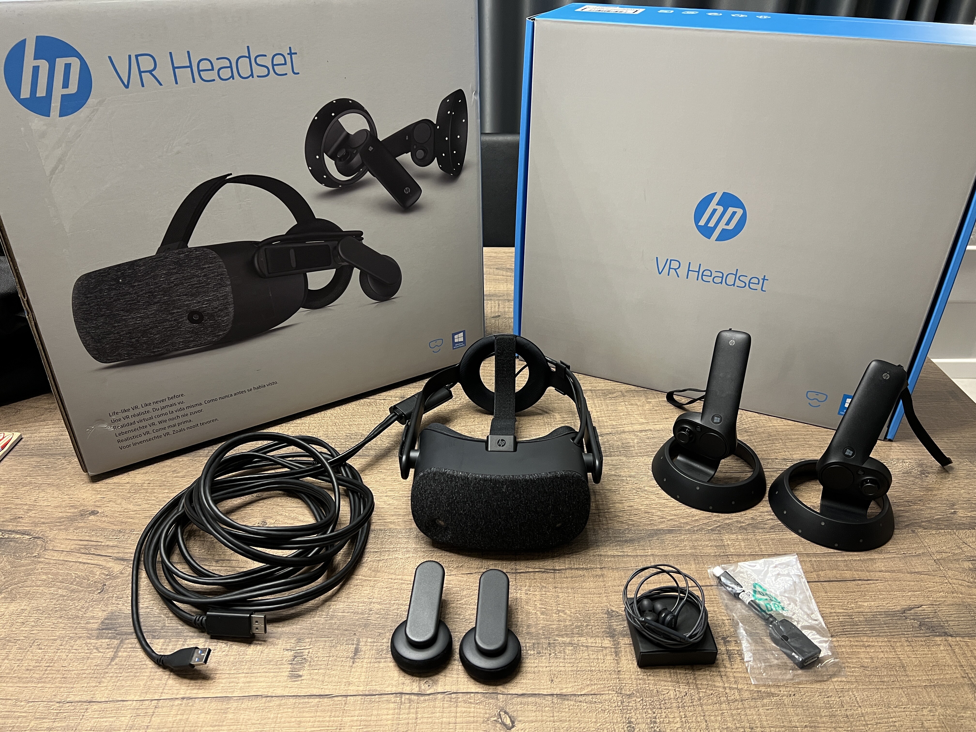
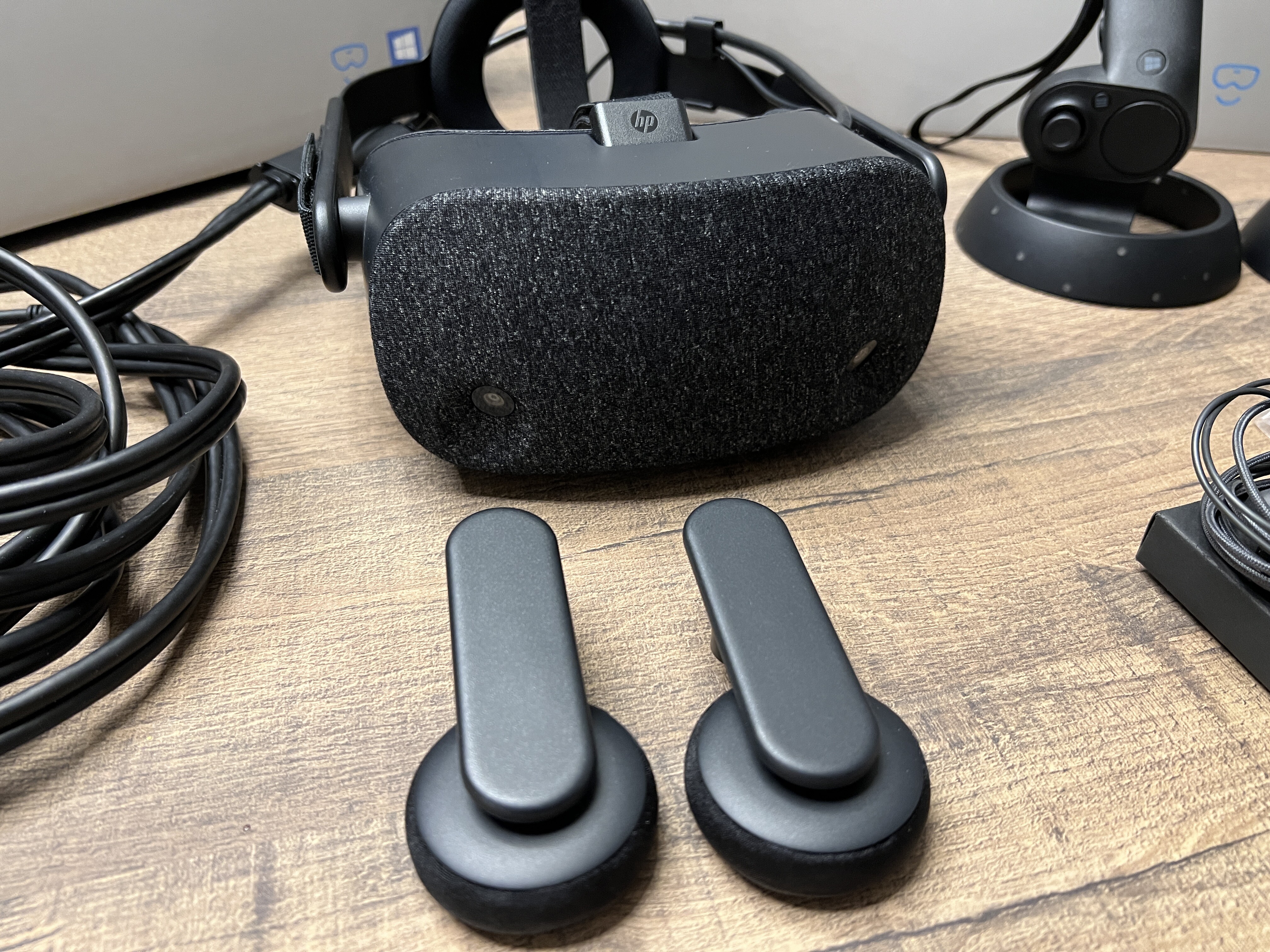
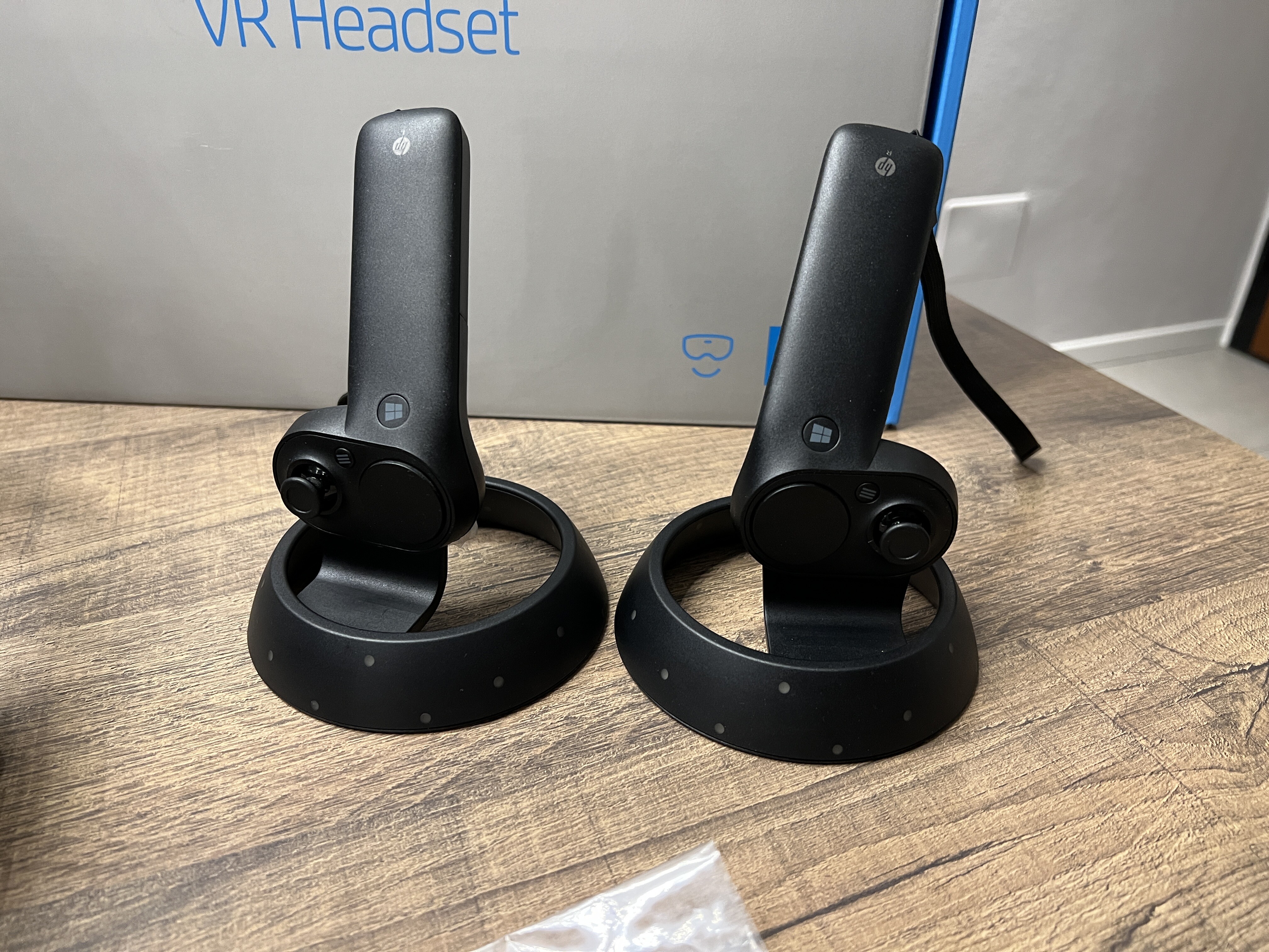
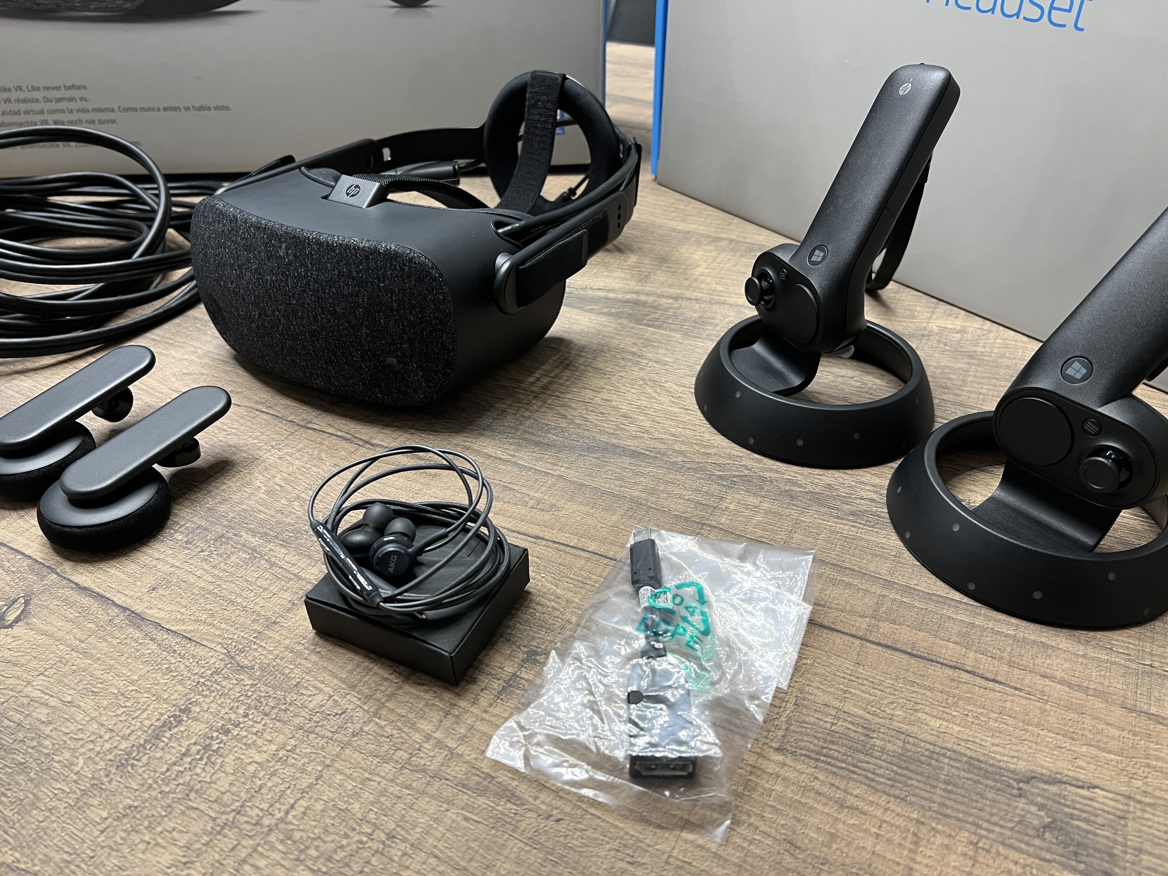
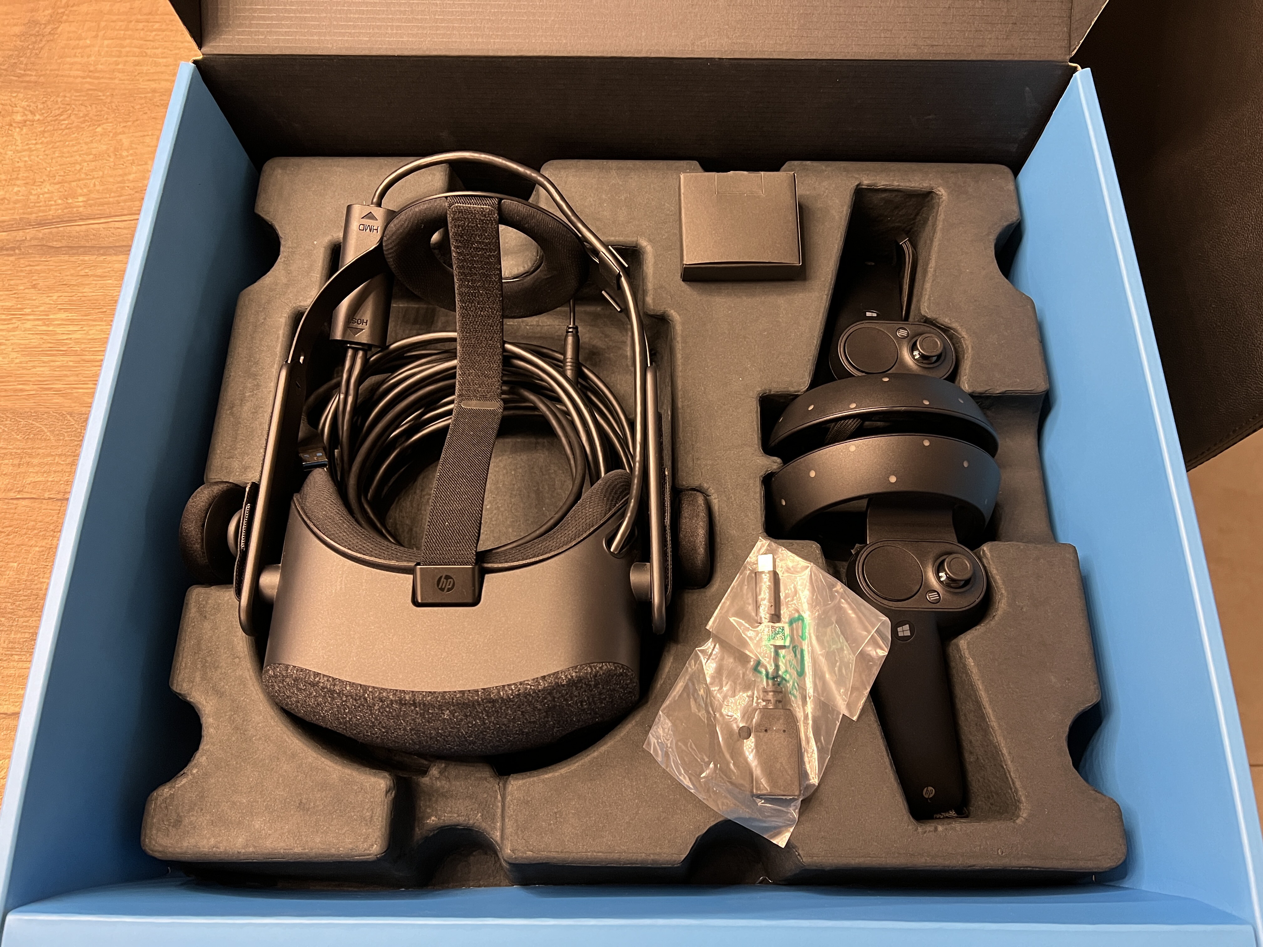
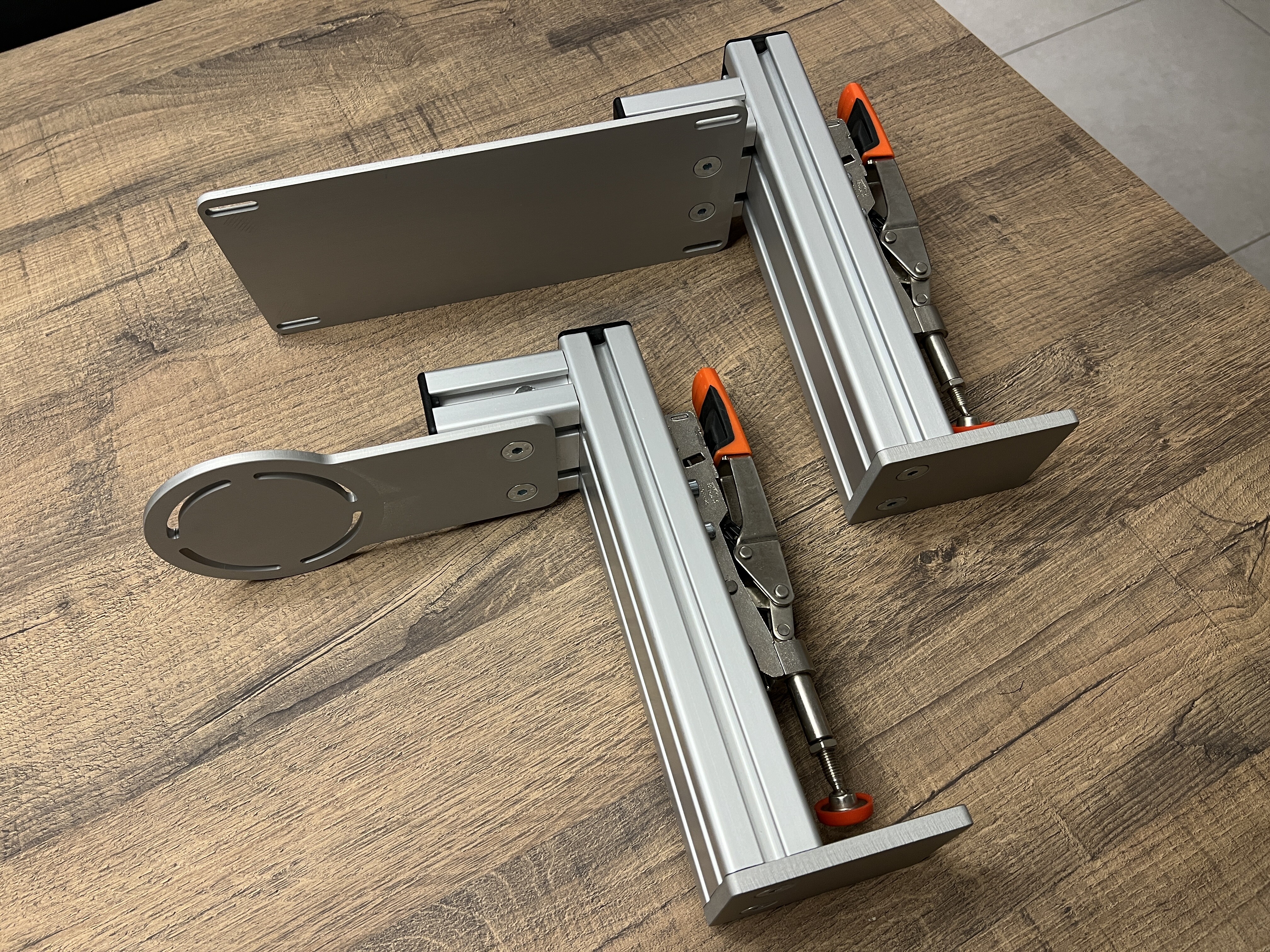
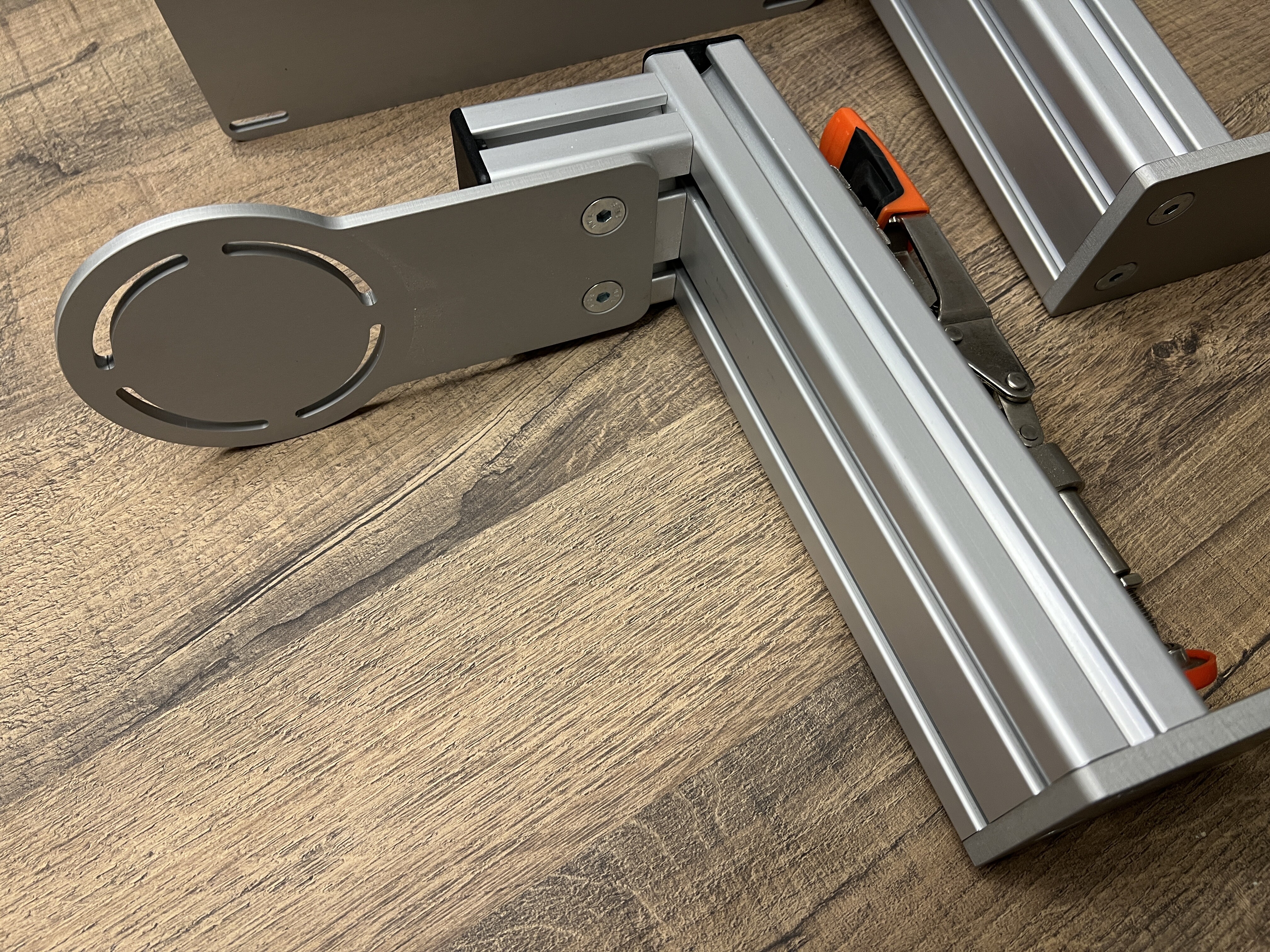
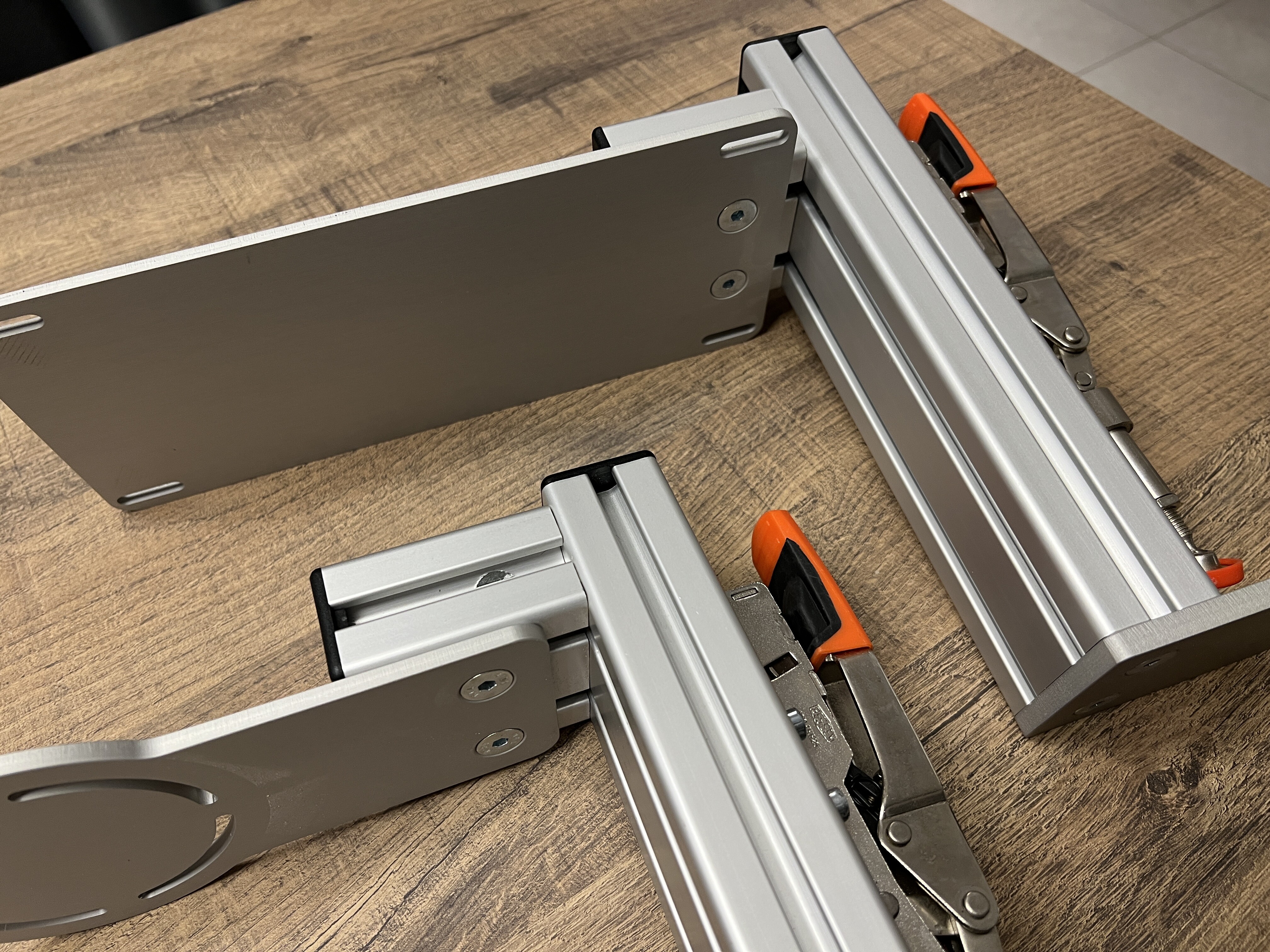
As per title very light use, excellent condition all accessories included price: 180€ Items are located in Italy, possible to ship at buyer expense.
-
As per title very light use, mint condition Price: 100€ - 1x TM warthog throttle table mount - 1x TM warthog joystick table mount - other accessories included from original packaging (spare screws, etc) Items are located in Italy, possible to ship at buyer expense.
-
You’re selecting the wrong column for the input device (in the picture you’ve selected TWSC throttle). Make sure you select the column under the device your trying to configure, e.g. TFRP pedals if you’re looking to bind the toe brakes to DCS also, ensure there are no double bindings for the same item . DCS auto-assigns default key binds to several inputs and its common to have conflicts when a new input device is added
-
Timelapse of a functioning RWR replica build Parts used: 2.8in round LCD display w/ controller board DCS export 3D printed bezel & PBC holder Laser cut lens from 2mm acrylic - engraved & white filled
-
Yeah I just put a resistor on the cathode. All the prints so far are done with my resin printer (I don’t have an FDM printer)
-
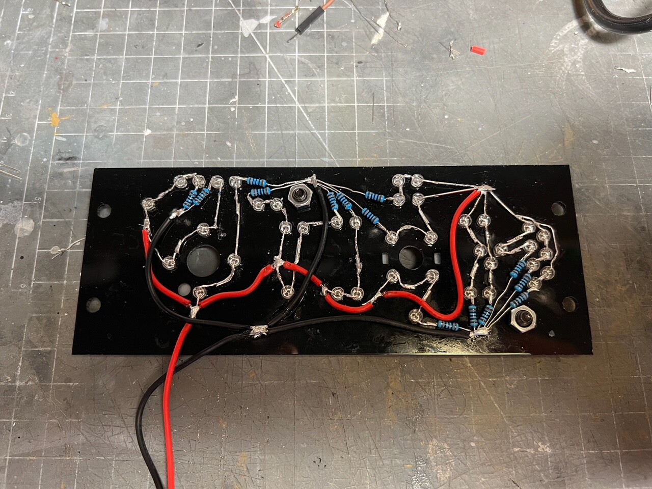
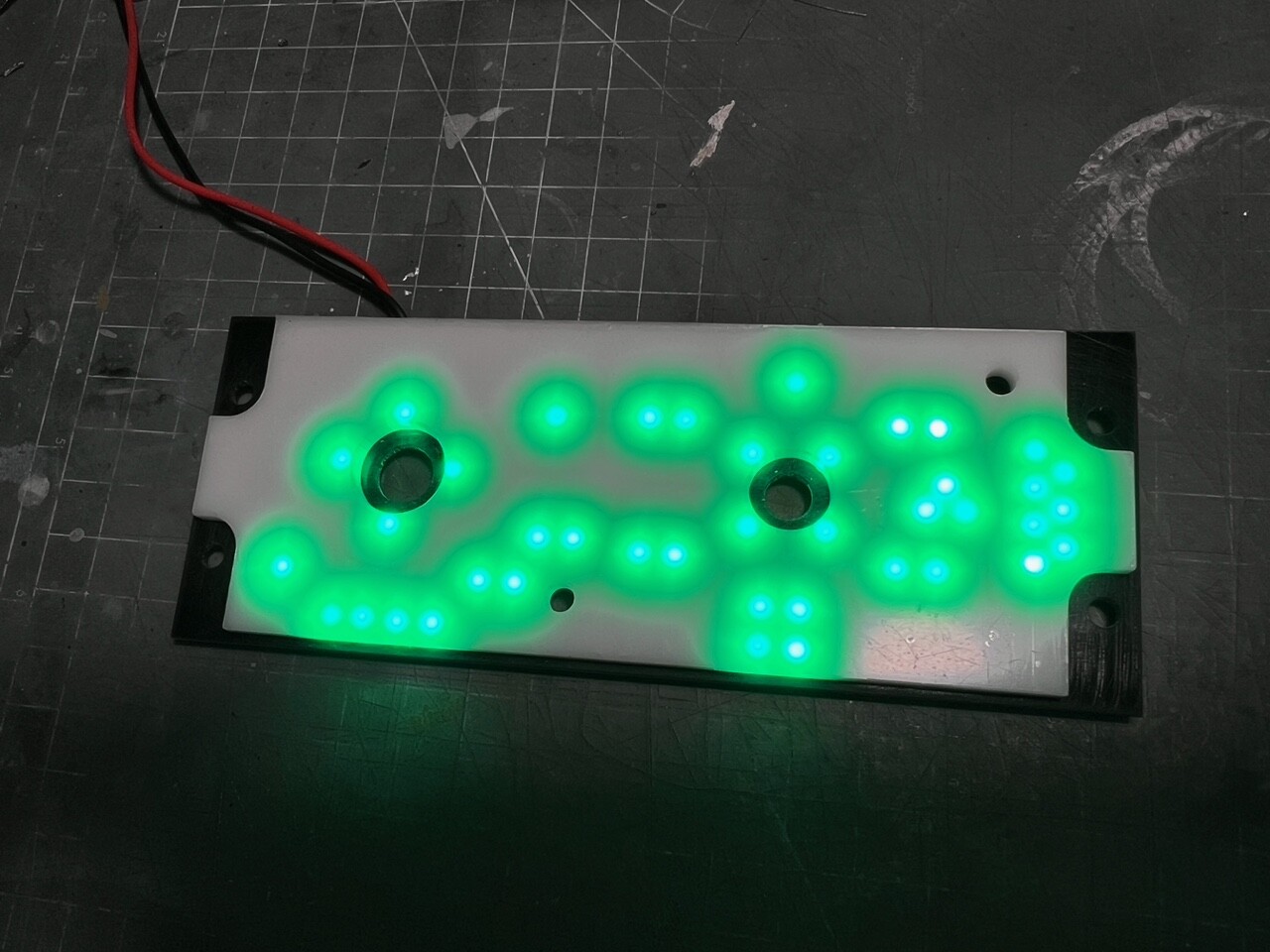
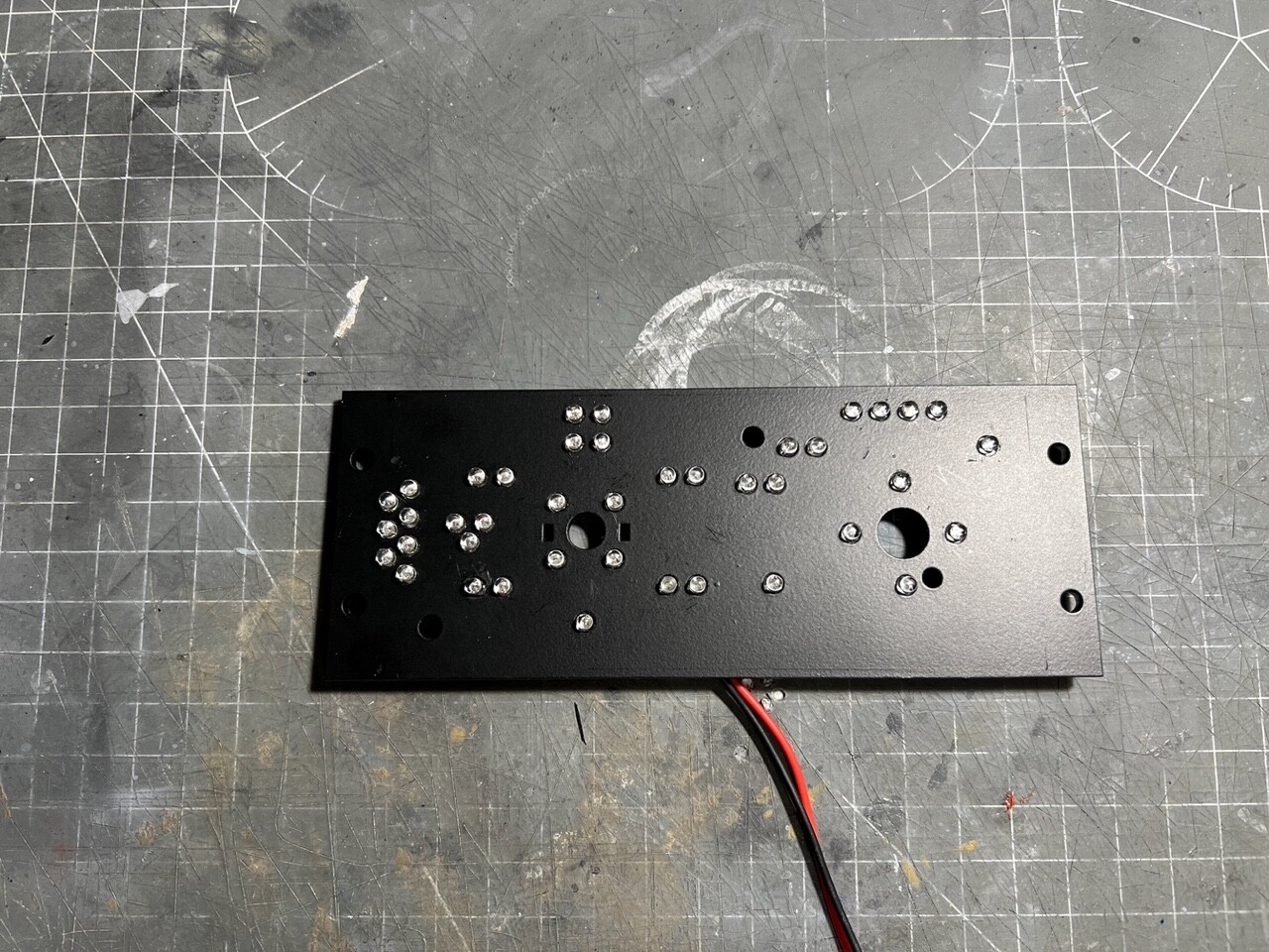
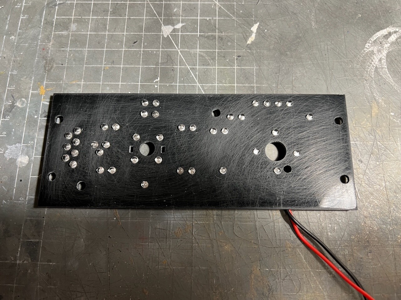
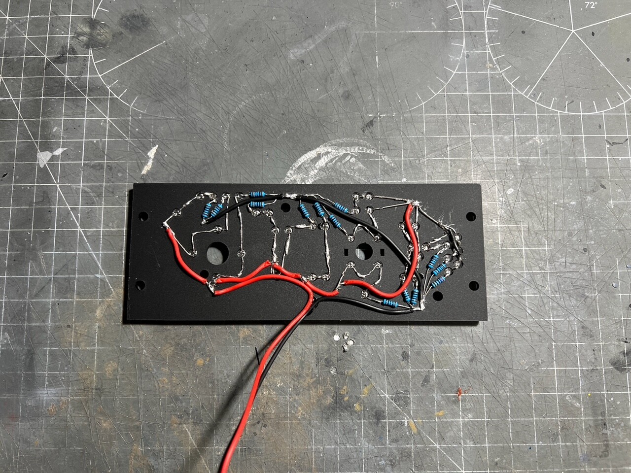
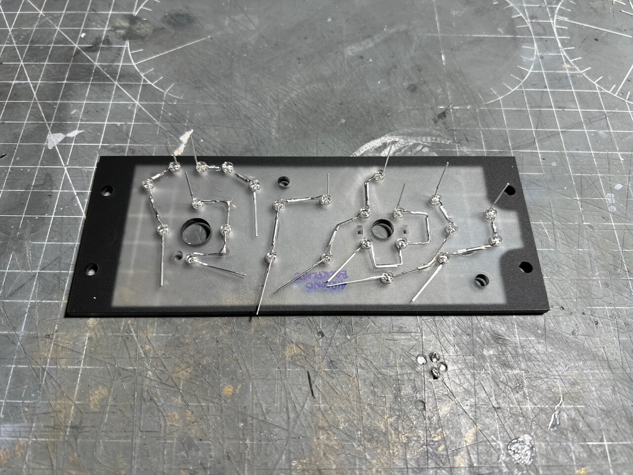
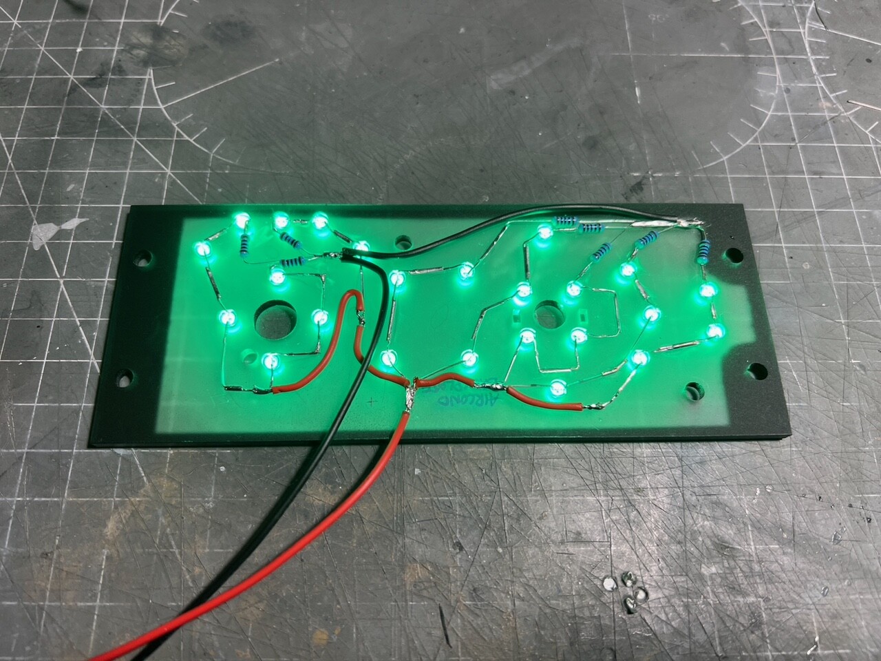
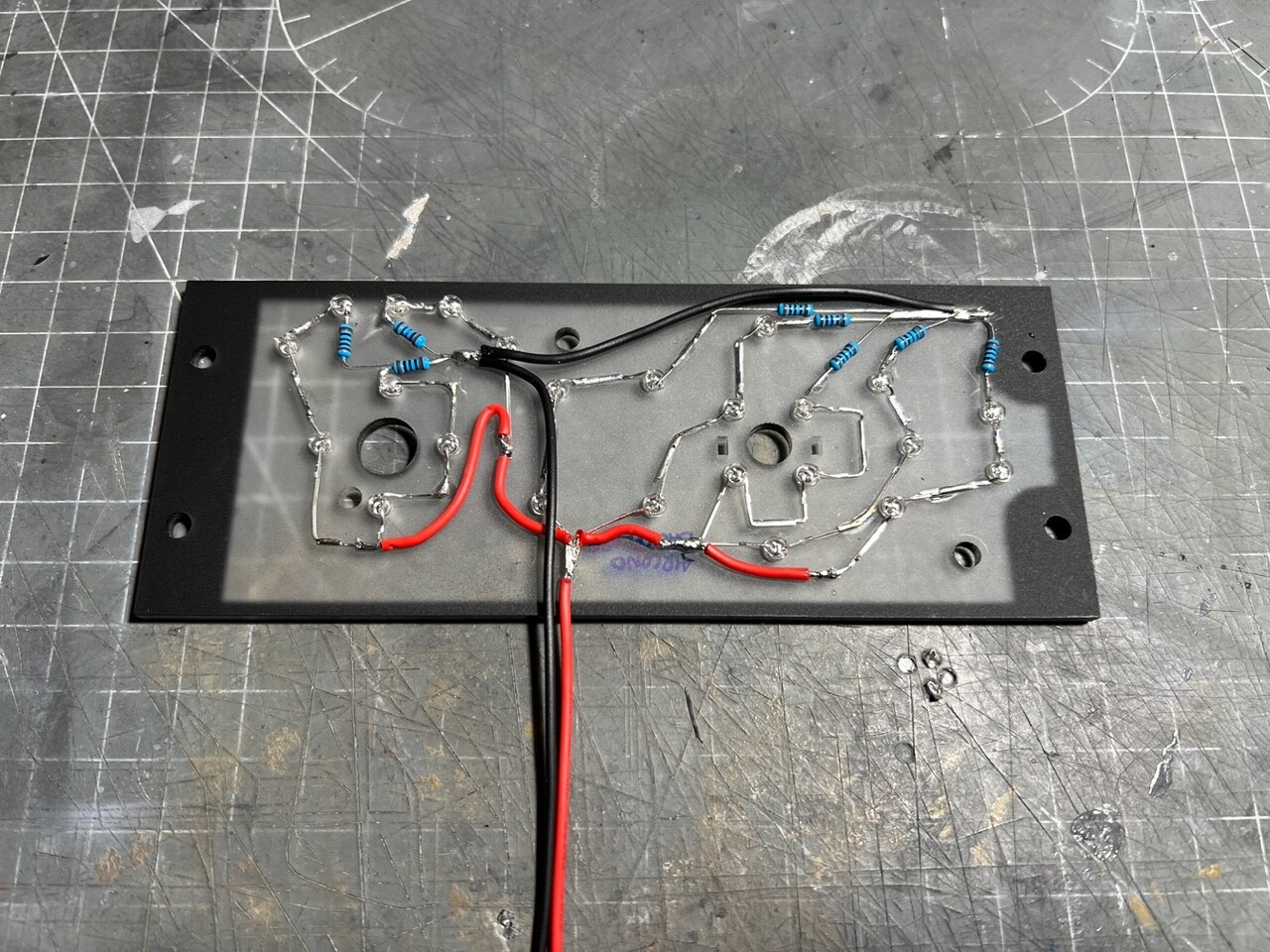
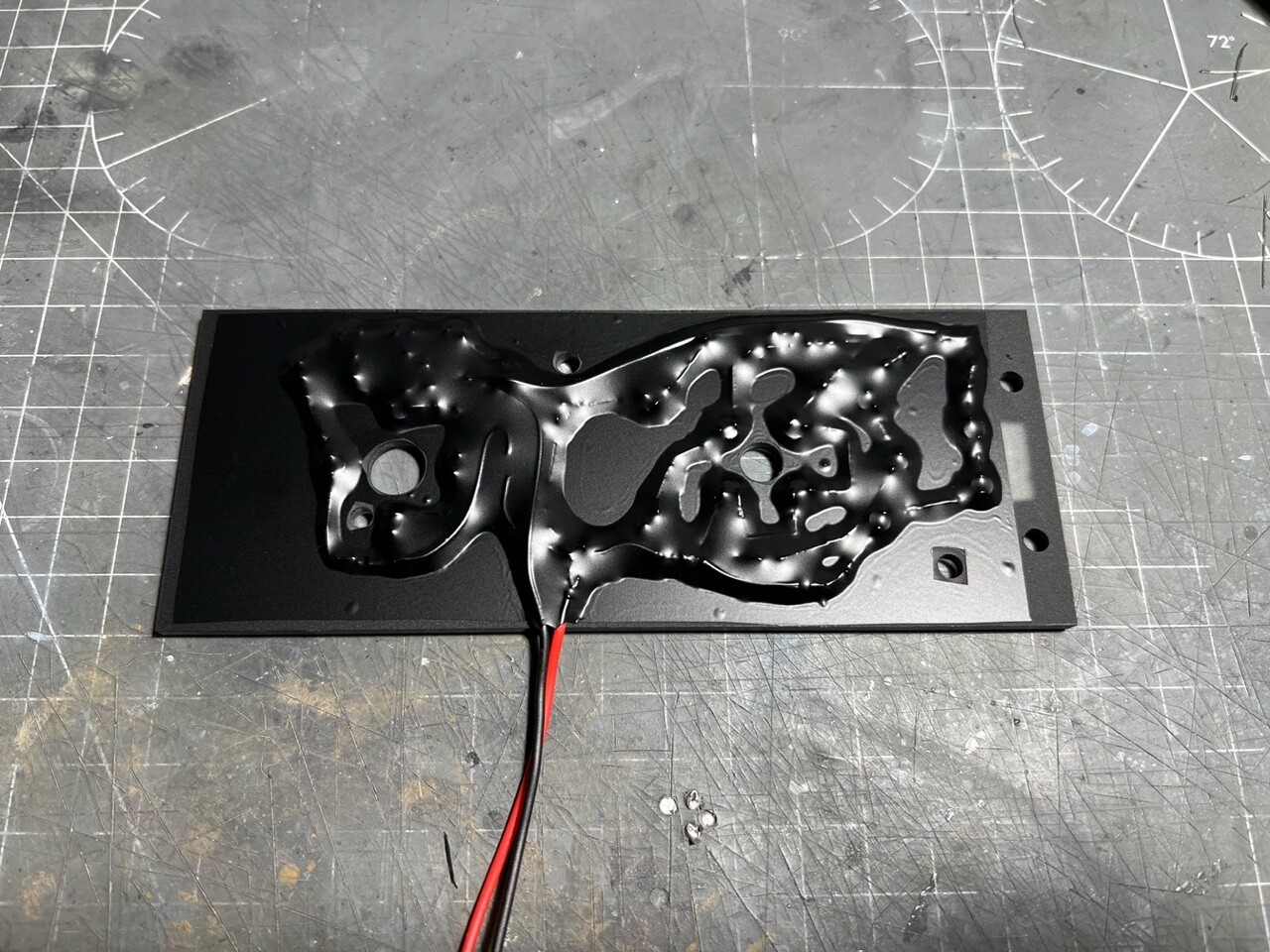
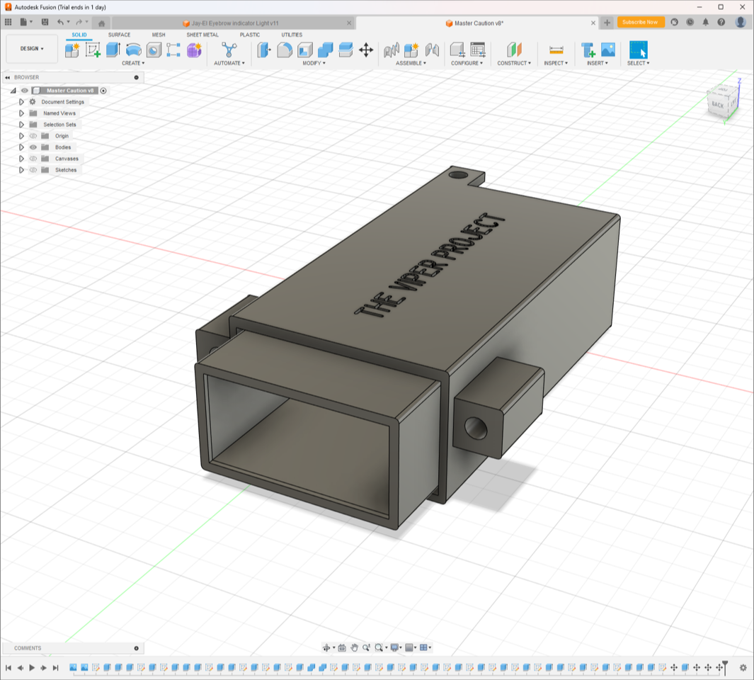
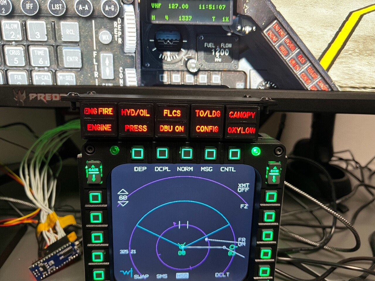
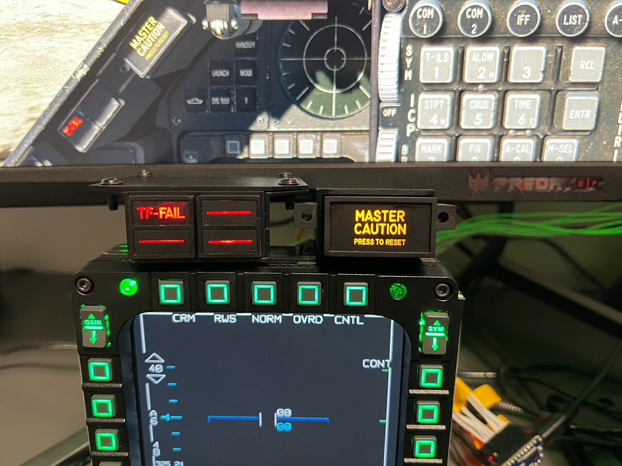
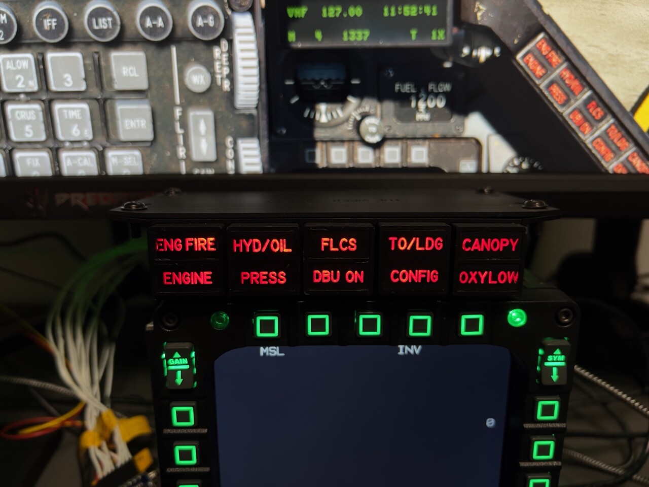
I'm using regular 3mm led which you can find everywhere (I bought mine on aliexpress) They're plenty bright, in fact I've had to wire a resistor to them to reduce the brightness. Here's some picture of the "V.2" (in the video it was without any resistor). I've added a lip inside the Jay-el replica to eliminate the light bleed on the perimeter of the lenses, and I've also designed and build the master caution light/pushbutton it's hard to take a nice picture of led lights, the camera always pics up the hotspots but in real life you can't see it again, excuse the wiring mess but it's just a testing rig
-
HAD stops locking on targets after a while. BUG or intended?
Snakedoc replied to Snakedoc's topic in DCS: F-16C Viper
so after a long time I found out why in my case it "stopped" locking targets on the HAD. It has to do with the Mark point DED page. If I have it open, even with the HAD as SOI using TMS up doesn't have any effect on locking HAD targets. If I get out of the Mark point page it works as intended. Wether this is a bug or feature I'm not sure -
Console lighting brigntess knob doesn't turn off backlight
Snakedoc replied to Snakedoc's topic in Bugs and Problems
any feedback on this? -
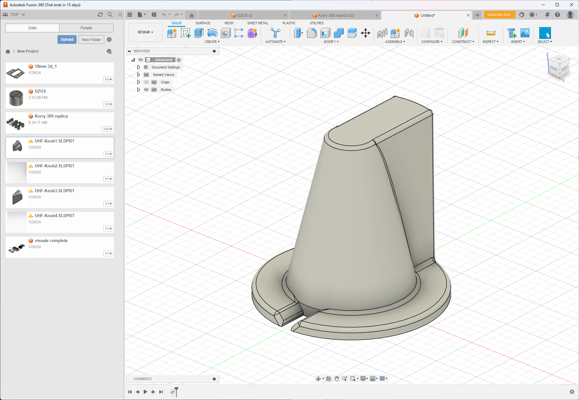
Thanks man I have printed some of the radio knobs already, will post pictures soon you can find the 3D model of the knobs here: https://drive.google.com/drive/mobile/folders/1_cFrojEq1pHJU_naOHi58j7Dr8RwRRJu I only modified them to have a 6mm diameter hole to accept the std rotaries shaft I discarded the above method of using individual LED lights to backlit the panels, I’m working on a method using a led strip which is easier and faster (will update here soon). I don’t glue the lightplate to the backplate, they’re just screwed together
-
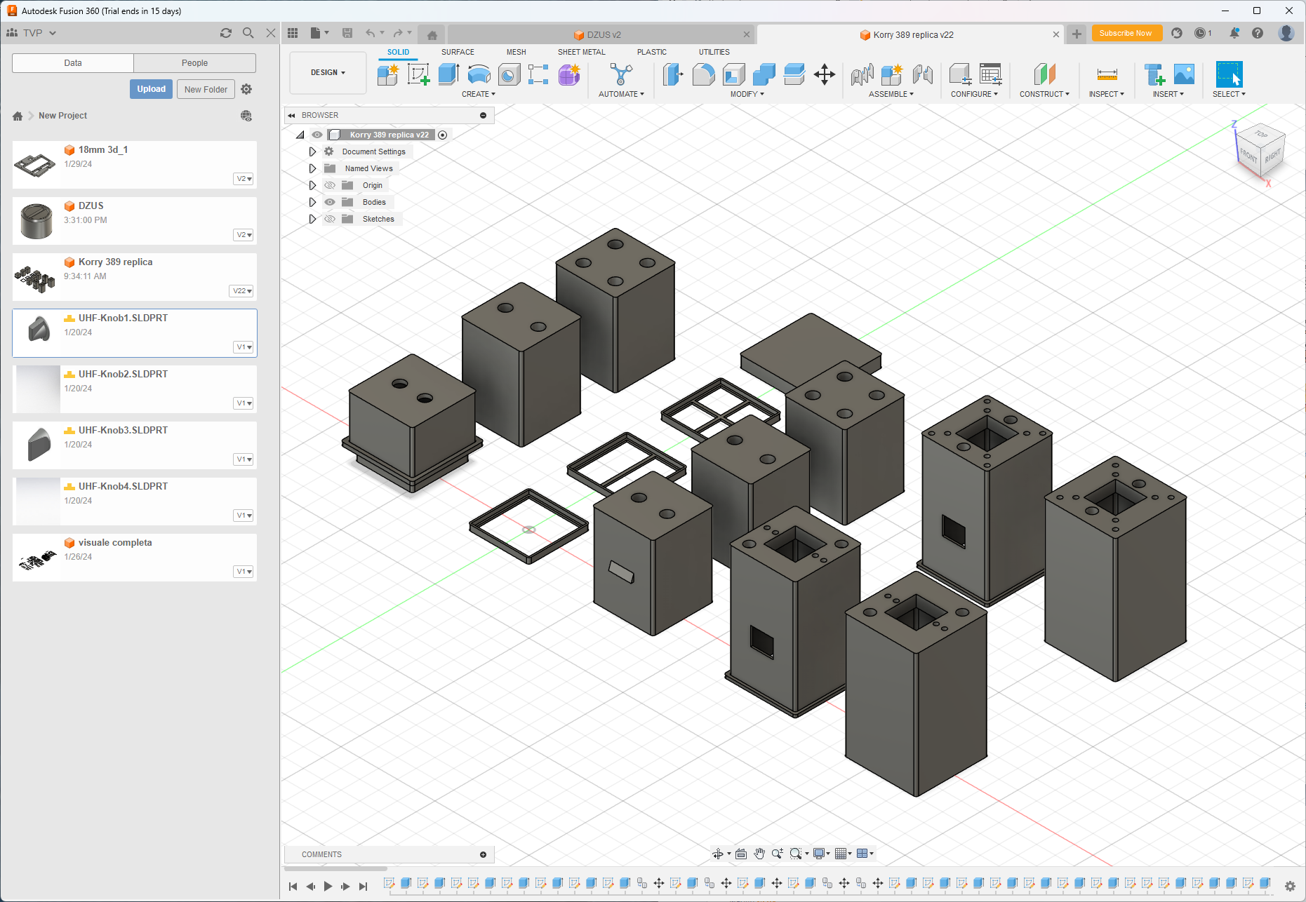
Still working on finalizing the design on the cockpit panels... Also, the first CNC shop I hired to cut the tub went on radio silence after 2 months of back and forth I've contacted a second shop and waiting on their reply In the meanwhile I've been working on some 3D objects like radio & panel knobs, annunciator lights, korry pushbuttons etc and I've also redesigned the DZUS screw caps I've attached the .stl file here in case anyone wants to print them ;D It's designed to fit an M4 bolt DZUS v3 M4(TVP).stl sneak peak of the other 3d objects PS: I may have purchased a fiber laser for better engraving quality
-
Hi, as per title, turning down completely the console brigtness knob doesn't turnoff the panel backlighting but just dims it. Not sure if it's intended or not (or if I'm doing something wrong) but the other two knobs (instr. panel & ded) work fine. track attached F16 backlight.trk
-
Awesome! Enjoy it!
-
Thank you sir! I buy my acrylic panels here: https://kunststofplatenshop.nl/ they have different branches of the same shop in many European countries
-
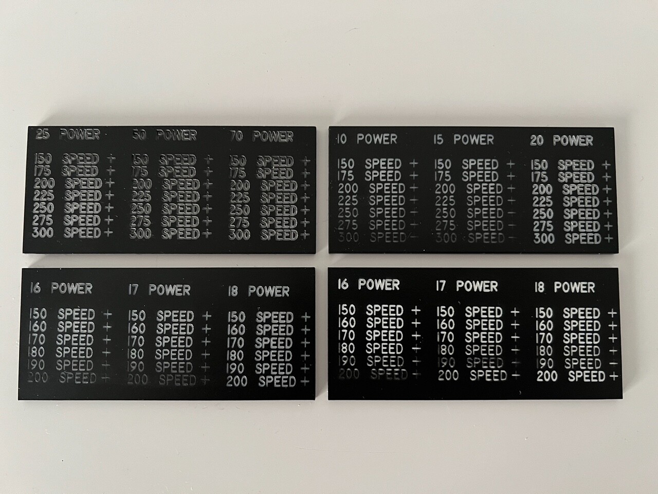
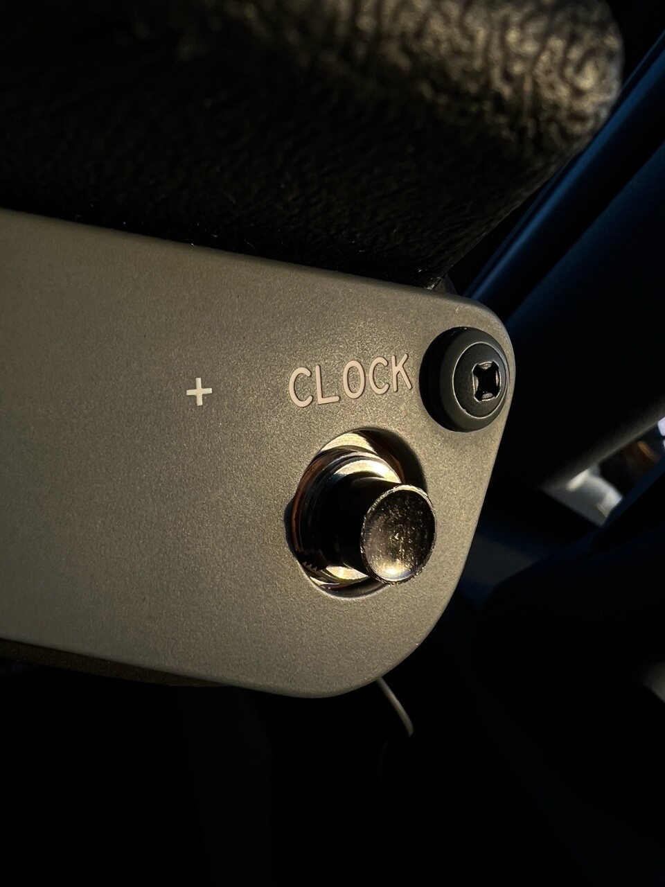
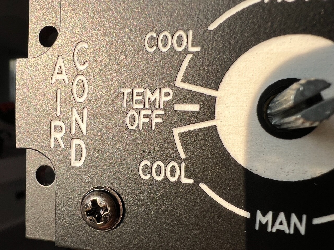
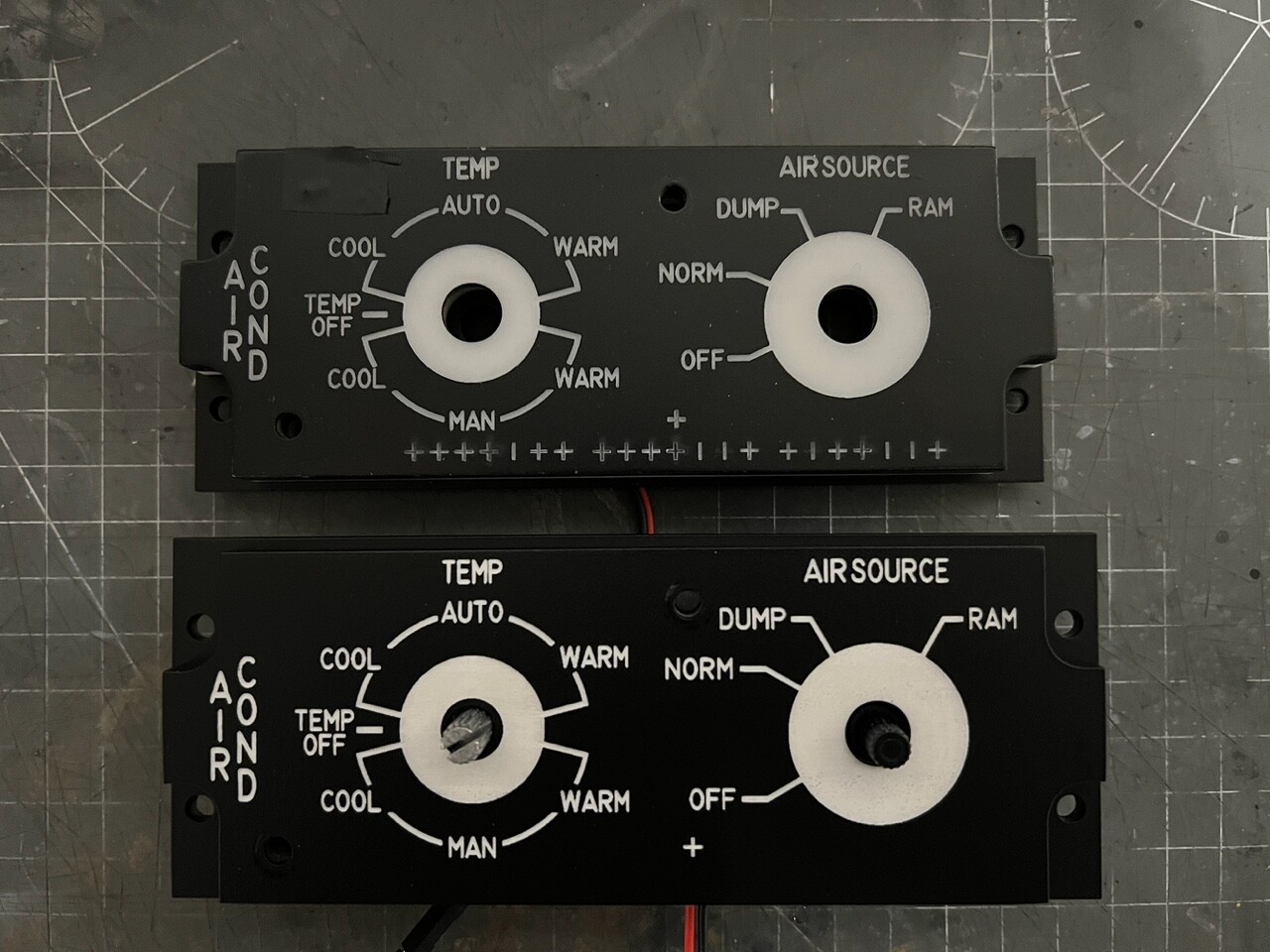
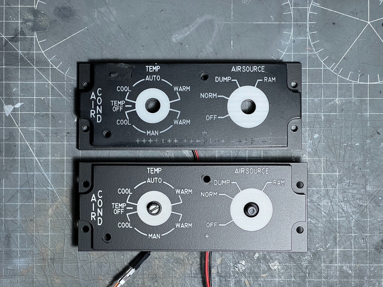
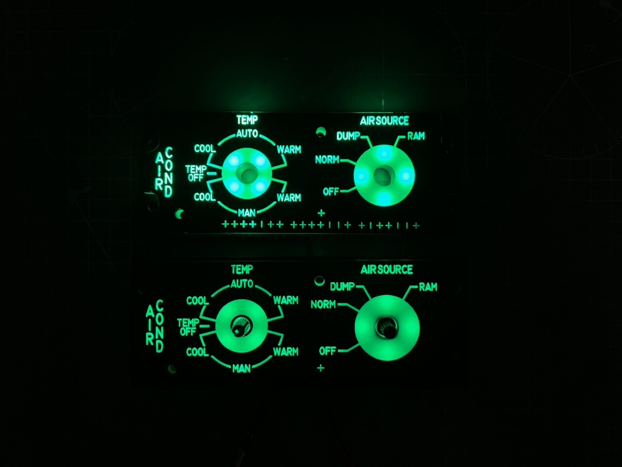
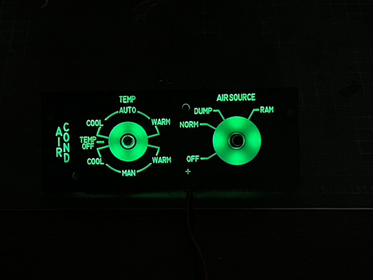
So a lot has happened in the last few weeks, I've been trying new designs, materials, led placements etc to find the best compromise in order to make the best possible panel reproduction. My original idea of 2mm/backplate (black) plus 6mm/lightplate (3mm matt/clear + 3mm opaque white) didn't quite work as I would have liked because of two issues: - the backplate was too thin, and although more realistic looking to the real one it didn't offer enough strength to remain straight and level, even the slightest pressure would cause it to warp and once mounted to the lightplate it would lead to a lot of light bleed from the gaps on its sides. So a decision to go for a 3mm thick plate was made (2mm plate, warped) - the lightplate is made by two halves, bottom transparent semi-gloss and top a opaque white. The bottom part was meant to diffuse the led lights but it just wouldn't do it enough and to avoid hotspots I had to space the led quite close to each other (and way too many led were needed for a single panel). The top part was opaque white and although it offered a good light transmission it was actually too much and the text was super bright. Also, with no backlight on the text wasn't exactly white instead it was transparent white, so it didn't look really nice. I decided to use the opaque white as the bottom half to diffuse the light and to use a 3mm solid white panel as the top half. (3mm plate, too many leds) A lot of testing was also done to find the best engraving setting to avoid text deformation, as you can see below I made many passes with various speeds & power setting. I found that speed 160mm/s & power 18% worked well for my setup. You can also see the difference between the "opaque white" and "solid white" panels (bottom left & right) (5 coats of black paint was used, then engraved) The engraving now is much better and the text is more accurate to the digital version, I've took a picture of a real aircraft panel (737-8) and you can see that the effect is almost the same. I maxed out my axis & laser resolution (1000dpi) so I can't get any more from it, but I'm happy with the results. And finally some pictures of the evolution of the designs, enjoy! (old at the top, new at the bottom.. ignore the many "crosses" on the top panel they were just more tests) (3mm backplate. I'm using matt-clear acrylic to diffuse light from the bottom, painted black & wrapped on the exposed areas) (old at the top, new at the bottom; same led full brightness but the bottom one has more diffusion and even backlight) I've been also messing with various Arduino boards and successfully connected them to the switches & DCS. Next I will be continuing to produce the rest of the cockpit panels and later coding the Arduino boards. I'm working on a video to explain the updated process, stay tuned PS: if you want to see more pictures and some short videos check out my IG I'll be posting more stuff there as well
-
I'm using MS33558 as font, it's the standard used in most US military cockpits In the videos I've made I talk about the design, cutting & engraving process. Not sure if you've seen it but here they are: https://www.youtube.com/watch?v=MO0TyCiiIzQ&t=155s https://www.youtube.com/watch?v=Cg3Lipbi4wo&t=51s If you've got any questions feel free to ask


.png.85a522659492b7025359ca343a176ddd.png)