RvETito
-
Posts
2541 -
Joined
-
Last visited
-
Days Won
7
Content Type
Profiles
Forums
Events
Everything posted by RvETito
-
That's a common design of all turboshaft engines - gas generator composed of compressor (axial, radial or mixed), combustion chamber and turbine driving the compressor and turbine machanically connected to a gearbox. That's why it's often called "free" (or "power") turbine because it has only gas dynamic "connection" to the other main components of the engine. The free turbine is the one that represents engine's power capabilites - the engine power rating is given as the output power at the FT shaft. And for it to provide that power it needs the gas generator to create the necessary gas flow to drive it.
-
A couple of things to clarify: - The engine is controled by four governors in total: 1. Ngg centrifugial mechanical governor - maintains the set gas-generator RPM 2. Nft centrifugial mechanical governor - maintains the nominal free-turbine (main rotor) RPM 3. EEG - electronic engine governor which has two functions - limiting the maximum Ngg as a function of the ambient static pressure and temperature and free-turbine overspeed protection by shuting down the engine in case of FT overspeed (which could happen in free-wheel clutch failure for example) 4. EGT electronic governor which limits the EGT up to 990'C regardless of ambient conditions. It sends signal to the command solenoid on the main engine control unit through the EEG, that's why sometimes the EGT limiting is "assigned" to the EEG but the EGT governor is actualy a completely independant device. The EEG sends command signal to the solenoid limiter (which activates up the amber lights on the overhead panel) either calculated by it's own Ngg threshold or by EGT governor threshold using "OR" logic i.e. whichever occurs first. The perfect engine adjustment would be when the two thresholds match - that means that you squeeze the maximum out of your engine. About the engine power indicator - it indicates compressor pressure ratio, not engine pressure ratio (according to Pratt&Whittney's term for EPR, being the only engine manufacturer that I know using it) and it's just a backup instrument of judging engine's power. The primary parameters are the Ngg, EGT and Nr. Also the power limiter operates in pulses - you can see the amber light flashing with increasing frequency if you smoothly increase engine power, the greater the frequency the bigger the fuel flow limitation. When they are steady lit up that means full (maximum) fuel flow limitation.
-
No, that's for free turbine (rotor) RPM governor failure.
-
In case the EEG is inop you may continue normal operation but you have to pay extreme attention at high power settings to avoid GG RPM and EGT overlimit. In general that means to look at the GG RPM and EGT gauges and when Ngg reaches take-off power (depends on the ambient temperature but in all cases is not more than 101.15%) and/or EGT 980-990'C - DO NOT increase the power of this engine (read do not pull on the collective more unless you move it's throttle lever from AUTO to Idle). This is how it works in BS, this how it works IRL ;)
-
Su-27UB full engine run. It is advised to check your volume prior watching this video http://www.youtube.com/watch?v=g9By6bPn3DM&feature=player_embedded
-
Yeah, Jens is like lost in space and one just has to whisper MiG-29K or anything related to the russian navy and here he comes :D Good to hear again from you, mate ;) Nice thread.
-
Nasty bird- http://www.youtube.com/watch?v=gc-XiO4ojzk&feature=related
-
Video from the first carrier ops of the new MiG-29K and KUB onboard of Kuznetsov http://www.vesti.ru/videos?vid=245068&p=1&sort=1&cid=1
-

Hinds are killing me, Vikhrs aren't doing much to prevent it
RvETito replied to advent_m's topic in DCS: Ka-50 Black Shark
If I were you I wouldn't be using the Vikhr, it doesn't track well maneuvering targets. Use the cannon instead, you'll outrange Mi-24's machine gun or cannon any time. -
Engine vibration in 3 minutes of dust - why?
RvETito replied to VS461's topic in DCS: Ka-50 Black Shark
The compressor deterioration by dust is made such on purpose for gameplay reasons- to avoid people flying unrealisticaly in the RIG zone all the time. No real pilot does that exactly because the dust affects powerplant's performance in long term. Not 100% sure but I doubt that the Ka-50 is equipped with IV-500E vibration monitoring system. It rather has IV-79P-V-2 but functionality is similar- one sensor on the each engine's forward mount. -
It is not always necessary to do that- normally the engine fuel control unit of the single operating engine will automaticaly increase it's power to take-off rating. This depends on adjustment so the option of moving the throttle levers above Auto is there juts to ensure that you can manualy set each engine to take-off power setting in case the automatic fuel control fails.
-
We already have the most wanted helicopter ;)
-
Sounds like reasonable numbers for the conditions you describe.
-
Fuel economy? :D
-
I'm affraid that requires hardcoding. As I said the EGT is a subject of adjustment via the IGV/VSV mehcanism i.e. you adjust the air mass flow through the compressor at given RPM. The very same manual you quote says that for the TV3-117VM (it's the same for the VMA) the maximum measured allowed EGT per mode are as follow: - idle - 780'C - 2nd cruise - 870'C - 1st cruise - 910'C - maximum continous (nominal)- 955'C - take-off - 990'C - emergency (2.5min power for VMA)- 990'C While for the paramaters given in the main chart are for operation of the engine on test bench in ISA conditions, without taking into account the exhaust nozzle, the dust protectors and the engine bleed system for anti-ice and other helicopter needs it says: - idle - 780'C max (usualy not defined, only RPM) - 2nd cruise - 770'C - 1st cruise - 815'C - maximum continous (nominal)- 855'C - take-off - 890'C - emergency (2.5min power for VMA)- 920'C So there are many factors that could affect those numbers and in service we always try to reach maximum EGT for the given RPM (power mode) because this is what gives output shaft power. I can tell you the difference- we had one Ka-32 (VMA engines) with very 'closed' compressor (VSV), it easily hit 100-101 % compressor RPM but could never reach EGT more than 920-930'C and the EEG was limitng it's power by gas-generator RPM. Another helicopter with exactly the same engines did 950-960'C at 99% Ngg and the difference in the abilities of the two identical helicopters to lift their load in equal conditions was obvious. So what you see in BS is the perfect case - RPM limit almost coincides with the EGT limit i.e. you get maximum engine hp ouput. You can tune the EGT by adjusting the VSV mechanism IRL and it's a common practice for some operators to increase their engines' service life. They reduce their power, making them colder in favor of longer TBO.
-
Congrats, you seem to have a trained eye ;) EGT/GG RPM is a subject of adjustment IRL via the IGV/VSV. What we have in BS is not incorrect, just the engines are "tuned" with more "open" compressors.
-
Another angle - http://www18.zippyshare.com/v/77998737/file.html
-
This claims to be 'safe' landing during MAKS. Here's a video of it-
-
-
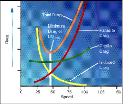
You have a point. The picture I posted represents the drag of the whole helicopter and it doesn't illustrate the unsteady character of the airflow around the rotor. It is much more complicated for a separate blade not that much because of the different velocities radiuswise but rather becasue of different velocities and angle of attack of each blade section in forward flight. The velocity at given radius varies with sinuous function in forward flight which causes the blade flapping which on another hand leads to angle of attack variation- AOA increase for the retreating blade and decrease for the advancing blade (blade selfdamping). That makes the drag picture very complicated- velocity has mostly effect on the induced drag while AOA affects both induced and profile drag. So in case of a single blade this graph is applicable for one particular azimuth where the flow could be observed as steady. Designers evaluate this very carefully. Crusial milestone is how the blade behave while retreating because this what limits helicopter's maximum airspeed due to retreating blade stall. For the advancing blade the main concern is the Mach number they reach at the tip. All these factors lead to a compromise for the choice of the blade airfoil - you want it thick at the retreating side and thin at the advancing. But since it should perform well enough at all azimuths an optimum decision must be found i.e. depends how fast you want your chopper to fly. This also gives the rotor diamater and nominal RPM. But for the flight dynamics studies the pariodical change of the airflow parameters around the rotor are only represented as inclination of the rotor lift vector and the drag charts are given for the whole helicopter.
-
Your efforts with the numbers are appreciated but I suspect some people dislike them pretty much since high school so I'll try to put it simpler :) It's all about aerodynamics- exactly the same as an airplane which has minimum drag airspeed, defined as the airspeed with lowest power settings demand i.e. airspeed you can fly with minimum power and have maximum excessive power available. The total drag is sum of the profile drag (which increases slowly with the airspeed), induced drag (decreases exponentialy with speed up) and parasite drag (increases exponentialy or parabolic to be exact ~V^2). This sum represents a curve with well defined minimum known as the most efficient airspeed- a speed that requires minimum power to keep level flight. It's all the same for the helicopter - profile drag of the blades which is almost constant with the airspeed, induced drag which is highest at hover and decreases exponentialy with the airspeed and parasite drag (total drag of all components which don't create lift). Ka-50 is a bit different because of the wings which have their input in the equation but that affects just the number, not the principle. So IAS ~130km/h is the one where the helicopter has lowest total drag i.e. it has the highest power excess. On the attached picture- yellow curve for the induced drag, green for the profile drag, red for the parasite drag and orange for the total drag. The numbers are applicable for light utility helicopter but the picture is all the same for their bigger brothers.

-
The 15km vs 8km range is correct- one is for the Su-25T, the other is for the Ka-50. I think I don't have to explain where the difference is coming from though the missile is all the same.
-
Actualy there is a DCS page in facebook- http://www.facebook.com/home.php?#/pages/DCS-Black-Shark/61145325560?ref=search
-
While I appreciate the humor I feel the need to say something serious. I don't wanna look like the team and myself personaly, being charged with the helicopter's physical model testing, are blind and deaf for any criticism. Actualy it's fully the opposite. We all will highly appreciate if a regular user finds any flaw in the code. After all this code is written by humans and that presumes mistakes. But I will (and I believe the rest of the team) thoroughly investigate only findings that are clearly described, physicaly argumented and backed up with selfexplaining tracks/screenshots. And I'll give an example straight away- some months ago a user found a bug with the vortex ring state being function of the ground speed instead of the indicated airspeed. It was something that we overlooked during the testing and I and Yo-Yo personaly thanked the user (pardon me but I forgot his nickname) for the good catch. I wish there were more people like him. So keep your eyes open once you understand what's going on in flight and don't hesitate to ask for cunsult or to post anything you find wrong but please provide correct evidence to back up your statement. Thank you.
-
Rotor wake is not modeled.