No1sonuk
-
Posts
1601 -
Joined
-
Last visited
Content Type
Profiles
Forums
Events
Everything posted by No1sonuk
-
Should also note that code is written for RS485 connection.
-
MFD EXPORT to 5 different aircraft with 2 files
No1sonuk replied to Spuds63's topic in Home Cockpits
There are no power cables on the monitors. Only the HDMI cables are connected. -
MFD EXPORT to 5 different aircraft with 2 files
No1sonuk replied to Spuds63's topic in Home Cockpits
Yeah. My screens work. I think the recognition might be a function of the adapter, though. Mine seems to think the monitors are there even if they're switched off. -
MFD EXPORT to 5 different aircraft with 2 files
No1sonuk replied to Spuds63's topic in Home Cockpits
Thanks. I have one of those USB to HDMI units for exactly this purpose. If I can run it through a hub, I can eliminate the long HDMI cables. Do you run any DCS-BIOS devices on the same USB hub? -
MFD EXPORT to 5 different aircraft with 2 files
No1sonuk replied to Spuds63's topic in Home Cockpits
So are you running the Startech HDMI adapter through a USB hub? Also, with Helios, you could put other instruments such as the HSI or ADI on the third monitor when running the A-10. -
Really nice in the air. PITA on the ground and in between!
-
IIRC, you can get clip-in prescription lenses.
-
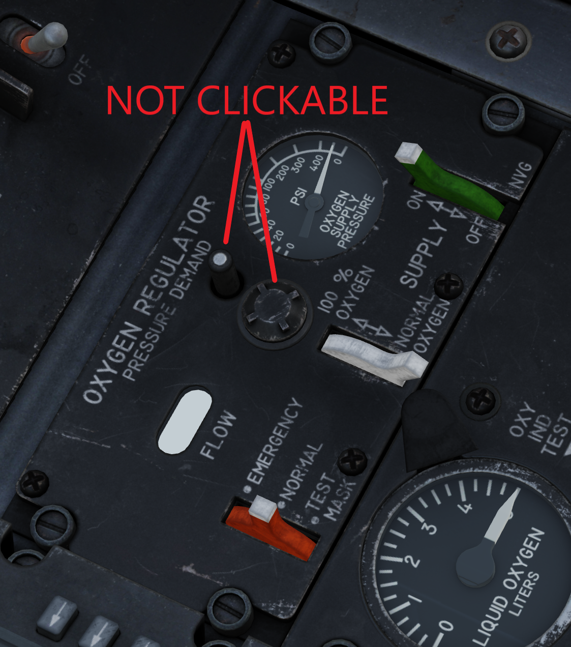
I'm guessing they're missing because they're not clickable.

-
Anything that uses the same frequency band can interfere. With digital signals, that usually manifests itself as breaking up on audio, low fps on video, or lag/reduced speeds for data. Bear in mind you'll be streaming A LOT of data for the VR. If that's on 5GHz, you need to be sure your audio is on 2.4GHz (e.g. the aforementioned laggy Bluetooth).
-
Bluetooth headphones have lag problems.
-
This is a callback to almost a year ago about the 1x1 viewport to make DCS render in external/HUD views. I think I finally found where it was I saw it: http://dcs-bios.a10c.de/docs/v0.7.0/userguide.html#_a_10c Looks like I misread the intention. This was to allow DCS-BIOS to export that data. I thought it was for other viewports too.
-
Can you not set up with #1 to the left and tell it the main viewport starts at, say 1920 from the left?
-
I saw something about that on comments for a YouTube video in the past day or so. If no one else chimes in, I'll have a search after work this evening.
-
How to Arduino micro pro power-supply for potentiometer
No1sonuk replied to Purzel's topic in Home Cockpits
The pot won't be seen by joy.cpl because you've set it up for use in DCS-BIOS, not as a joystick axis. Try this: DcsBios::Potentiometer hudSymBrt("HUD_SYM_BRT", A9); You don't need the pinMode statements for I/O only used by DCS-BIOS - it does that automatically. AND everything I've read says you don't need it at all for analogue pins as it's automatically set when the analogRead function is called. Also remember that pins 0 and 1 can't be used for normal I/O on ATMega328 Arduinos such as the Uno and Nano. It should be OK for the 32u4 devices like the Pro Micro. If you want it to be aircraft-specific, you could do it all in DCS-BIOS, like this: #define DCSBIOS_DEFAULT_SERIAL #include "DcsBios.h" DcsBios::Switch2Pos hookLever("HOOK_LEVER", 3); DcsBios::Switch2Pos gearLever("GEAR_LEVER", 2); DcsBios::Potentiometer hudSymBrt("HUD_SYM_BRT", A9); DcsBios::LED landingGearHandleLt(0x7478, 0x0800, 0); DcsBios::LED hookLever(0x74a2, 0x0100, 1); void setup() { DcsBios::setup(); } void loop() { DcsBios::loop(); } -
How to Arduino micro pro power-supply for potentiometer
No1sonuk replied to Purzel's topic in Home Cockpits
It SHOULD be VCC. That's the power rail of the processor. Have you tried a different pot? You might have a faulty one that's shorting the power supply. -
OR, put a hinge pin through the spherial part. Check out how they stop this illuminated switch rotating - Take a close look at the side of the thread: https://www.12voltplanet.co.uk/P00741.html?gclid=CjwKCAiAxP2eBhBiEiwA5puhNcE9EYiUtqlSY-68IHWtcvKqQ1FwQwvF87rp8wVL5ZbpvhVcc9Jq6BoC95gQAvD_BwE
-
Increasing the sensitivity of IR digital position sensor
No1sonuk replied to lesthegrngo's topic in Home Cockpits
If it can detect white paper at 1", it should be able to detect speed tape further away. Yes. Have a look here (and note the smaller resistor value for the LED): https://www.digikey.com/en/maker/blogs/2022/how-to-use-a-phototransistor-with-an-arduino -
Increasing the sensitivity of IR digital position sensor
No1sonuk replied to lesthegrngo's topic in Home Cockpits
The mirror finish balloon stuff is usually called Mylar. I've got what's called "speed tape" in the aviation industry. It's basically very thin self-adhesive aluminium that's used for temporary patching of aerodynamic surfaces. You could possibly try kitchen foil and double-sided tape or glue (or even just wrap it around the needle to test it). As for the electronics: The op-amp is set up as a comparator. The potentiometer is being used as a voltage divider to set the detection threshold. With the circuit you have there, it's set up to trigger the output LOW when the input created by the R3 and phototransistor voltage divider drops below what you have set on the potentiometer when the light falls on the sensor. Because it's used as a voltage divider, changing the potentiometer value will have no effect beyond changing how much current the overall curcuit uses. I don't think changing R3 will either. And remember that you're using a device with an A-D converter... You could get rid of the hardware comparator entirely and read the voltage from the phototransistor, then compare it digitally. Another, easier, option is to make the LED brighter: The datasheet for the TCRT5000L shows the LED forward current can be up to 60mA. With an LED forward voltage of 1.5V, and 5V supply, 390 ohms at R2 gives a current of just over 8.97mA. That means you could drop the resistor, R2, as far as 100 ohms and get 35mA to get a "brighter" LED. Still within the range, but the LED may get warm. Just remember not to go lower than 175 ohms (20mA) if you're going to drive the LED directly from an Arduino pin so you can turn it on and off as required. -
Increasing the sensitivity of IR digital position sensor
No1sonuk replied to lesthegrngo's topic in Home Cockpits
Could the needle be too close to be detected? Some useful info here: https://www.vishay.com/docs/80107/80107.pdf -
Advice requested for a small but irritating soldering issue
No1sonuk replied to lesthegrngo's topic in Home Cockpits
If it's lead-free solder (e.g. SAC), the temperature needs to be higher. -
Advice requested for a small but irritating soldering issue
No1sonuk replied to lesthegrngo's topic in Home Cockpits
I don't think so. -
That's exactly it. Maybe it'll stop working soon.
-
Advice requested for a small but irritating soldering issue
No1sonuk replied to lesthegrngo's topic in Home Cockpits
And on the tip cleaning note. While the "traditional" method is a damp sponge, I prefer the "metal shavings" type, as they don't cool the iron when they work. e.g. https://www.amazon.co.uk/Soldering-Cleaner-Solder-Cleaning-Brass/dp/B09GY5DFDW/ref=sr_1_1_sspa?crid=35XR9J9S8QXY2 -
Advice requested for a small but irritating soldering issue
No1sonuk replied to lesthegrngo's topic in Home Cockpits
Part of the problem is often too much solder. The excess sticks to the iron rather than the joint. -
Search for OLED and altimeter. You should find a few discussions which describe driving the OLEDs with "rolling number wheels". You'd just need to adapt the code for the FFI. Just remember it's processor-intensive, so don't expect to be able to run much else, if anything, on the same device.