No1sonuk
-
Posts
1601 -
Joined
-
Last visited
Content Type
Profiles
Forums
Events
Everything posted by No1sonuk
-
OK. No need to get defensive... My initial reaction was "F**K IT sort it yourself." However, I'll cut you some slack this time as you might have misread my comment. I'm trying to determine if you cocked up some arduino code that's leading to your problem. As you appear to have gone straight to Helios, I will suggest trying to bind the switches in the normal controls screen in DCS. Start with the switches in the middle, "ON" position. Bind the MENU position by switching up and releasing. Then bind the ON/OFF by switching down to "OFF". This may be redundant if you've checked the button press output in the Windows USB Game Controller settings app: How have you wired the Bodnar board? Are you using the breakout with diodes? If not, did you put your own diodes in?
-
You wrote "programming my CMSP panel". What programming? I thought you were using a Bodnar board for the switches.
-
Have you checked the control binds aren't clashing? I know that causes odd behaviour with analogue axes, but maybe that's also a problem for some standard buttons/switches.
-
Yes. I use Open Beta with DCS-BIOS.
-
Did you change the properties of the updater to run in the directory you moved it to? If you just move the files, the original run location may be retained.
-
IIRC, you move the updater file to the drive/folder you want and run it. It then installs the files there. That's how I copied my DCS to a new PC.
-
Raspberry Pi Pico $4 controller for USB interface
No1sonuk replied to Sprool's topic in Home Cockpits
I doubt it. The code is written for Arduinos. Having said that, the Flightpanels fork can run Streamdecks, so I don't know for sure. -
The MFD screens are square, so the output from DCS should be square and repositioned/scaled to fit the space inside the buttons. IIRC, the resolution of the real ones is 600x600, but if 720x720 fits, that's what you use. As for the taskbars: Right click on one and select taskbar settings. There are options there to turn them off on multi-display setups.
-
TBH, my comment was originally aimed at Hempstead, but I noticed after posting that it had jumped to a new page AND kind of answered your question as well.
-
Have you considered a Bodnar board for the USB interface? 32 buttons (in a matrix ) + 4-way hat + 8 12-bit analogue (which I know can read analogue Hall sensors).
-
IIRC, the reason most people use shift registers is to make the grips compatible with Warthog, etc. bases, and Thrustmaster used them so they could use a 5-pin connector instead of more than 20...
-
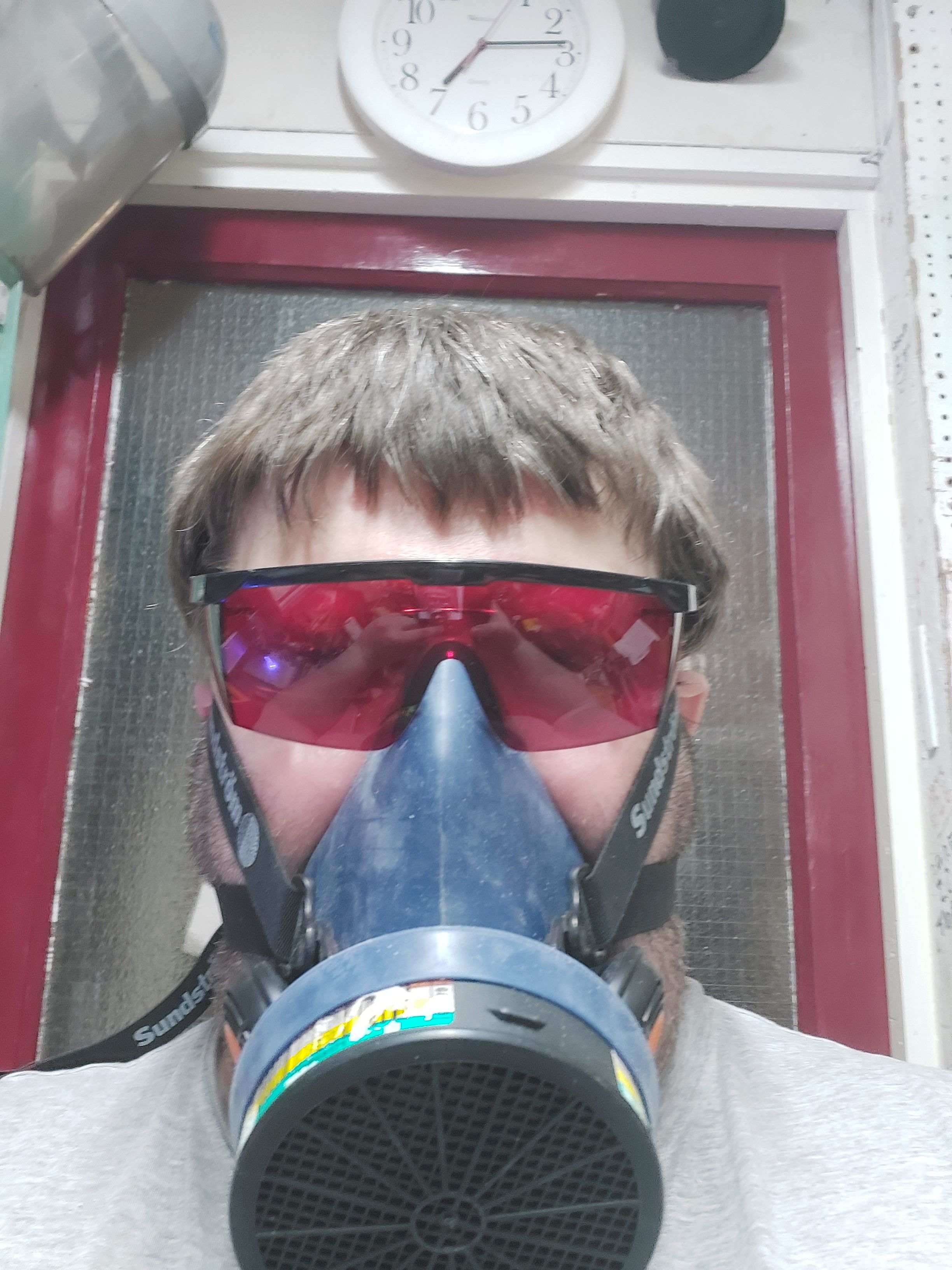
The dust isn't as much of a problem as the toxic fumes produced by burning plastics.
-
Yup. That's OK. Too much?

-
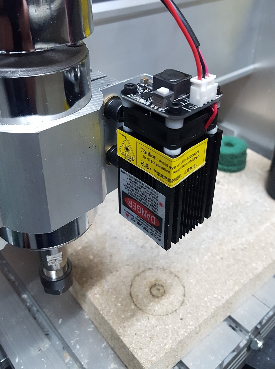
Yeah. I have chips EVERYWHERE!! BTW, this is my 3040 CNC router with a 2.5W blue/violet diode laser fitted.
-
Make a bit fan. Worry less about overheating the cut.
-
Regarding cutting plastic with the cnc router: I use a "bit fan" which blows air down as it spins. This cools the cut and blows the chips away.
-
Have a look here for what can be done if you combine CNC router, added laser engraver, 3D printer and manual lathe:
-
Which is why I said "not entirely accurate". Having PROVED what I wanted to do works...
-
Have a look at the "ActionButton " command in DCS-BIOS.
-
It's in the normal control reference document. e.g. The command ref says this: DcsBios::Switch2Pos masterCaution("MASTER_CAUTION", PIN); The bit in red is the command for sendDcsBiosMessage, so the arduino code to set the switch to on in DCS is: sendDcsBiosMessage("MASTER_CAUTION", "1"); Change the "1" to "0" to turn it off. Change the "1" to "2" if it's the third of a 3-position switch and so on. IIRC, "TOGGLE", "INC" and "DEC" also work, as well as the custom increment and decrement. e.g. "-3200" and "+3200". The "advanced" view in the control reference tells you what values DCS expects. Note that if you are generating the number for sendDcsBiosMessage in your code (e.g. for an analogue control), it has to be sent as a string, not an integer.
-
Maybe DCS is set for "full screen"? No idea if that's even related to your problem.
-
Not entirely accurate... I just CONFIRMED that the Pico 4, with this adapter CAN connect to a PC via a gigabit switch. https://www.amazon.co.uk/dp/B08Q36HB3G?psc=1&ref=ppx_yo2ov_dt_b_product_details In fact, my home network switch (Netgear GS108) is rated 1G and I had VD reporting "5 GHz | 1200 Mbs" with the headset's Wifi turned OFF. That switch is connected to my ISP router, but the home network is only connected to the switch. I'd be quite happy with extending that setup if I wasn't returning the Pico 4 because of other issues - Primarily image quality WRT a normal monitor, and motion sickness issues. Also, I prefer the head tracking setup and being able to use my mouse and keyboard.
-
It's not the controls that will stop working, it's that app which shows the data that is going to be unavailable. IIRC, someone has crated an alternative for that.
-
Not as far as I know.
-
So can I use this to connect the PC to the USB-ethernet adapter: https://www.amazon.co.uk/NETGEAR-Ethernet-Unmanaged-Internet-Splitter/dp/B07PYSNSDD/ref=sr_1_1_sspa?crid=1GSTS2VEX532U&keywords=gigabit+switch&qid=1672615191&sprefix=gigabit%2Caps%2C75&sr=8-1-spons&sp_csd=d2lkZ2V0TmFtZT1zcF9hdGY&psc=1