Robin_Hood
-
Posts
983 -
Joined
-
Last visited
Content Type
Profiles
Forums
Events
Everything posted by Robin_Hood
-
I used to do 350 Kts, Idle, 60°, no airbrakes, and now I have to add power halfway through the turn. I would be surprised if adding airbrakes improves things, but I'll try. What airspeed do you expect at the end of the turn ? EDIT: Heres what happens when I try this (Track and Tacview attached) ; 60°, idle, airbrake out, 180° level turn, airbrake in at 200-220 kts. I run out of energy before the end of the turn. Do you guys make a level or descending turn ? M2KC Overhead break.zip
-
Hi all, I am wondering whate are everybody's parameters for the overhead break. With the new flight model, it seems that the aircraft loses a lot of energy at idle throttle and I have to add power in the middle of the break to keep some airspeed. I hava seen various parameters over the year, but currently none work for me (and airbrakes are especially no-no). I wonder if people have thoughts on the subject.
-

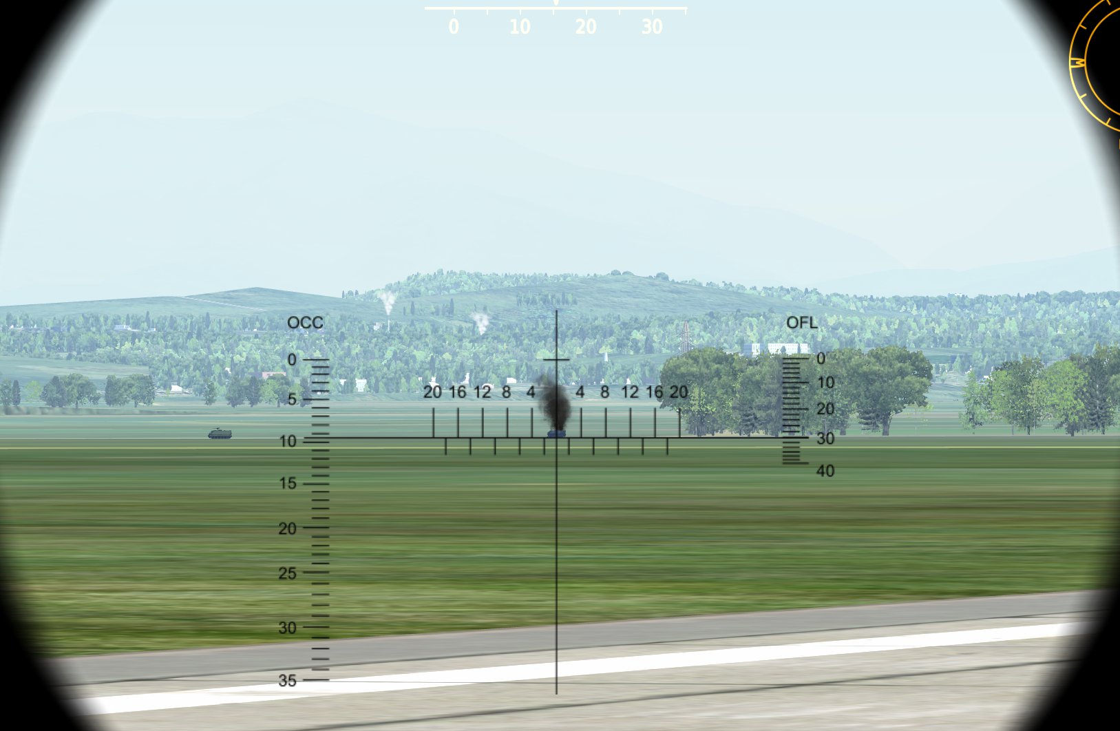
Explanation of all numbers/letter on radar screen please?
Robin_Hood replied to D4n's topic in M-2000
Actually, both definitions exist. I believe the Navy uses (or used) that one.* But yes, the other one (head-on=180°) is the more widely used and logical. What I didn't realised is that, acording to jojo (didn't check), the Mirage actually uses both définitions, one on the HUD and the other on the VTB. Now that can be confusing. I imagine it has something to do with different thought process for intercept and close combat. *: Can't find a solid reference now, unfortunately. I'd did notice that some official Brevity codes gives aspect definitions (HOT, FLANK, etc...) with both methods (ex: HOT is "CONTACT aspect stabilized at 160-180 degrees angle from tail or 0 – 20 degrees angle from nose." There must be a reason why they feel they have to give the angles from the nose. EDIT: Found a reference, in CNATRA P825 - Air To Air Intercept Procédures (2010), Appendix C - Multiservice Brevity Codes -
Got it. The way I did it was more of a workaround anyway. What would be really great would be that the cockpit= function doesn't default in the CA folder. This would not bypass CA entirely, as the module would still be required in order to take control of the unit, so I think it would be something nice to allow.
-
Hi Since the new stable update (1.5.8.xxx), mods will apparently only work when placed in the Saved Games folder. This was not unexpected, but it highlights the problem I mentionned here. My custom cockpits for CA do not work anymore, because they had to be in the game's directory. I have still not found a workaround. I would really like a word from ED on this, even if it is to say that they do not want custom CA cockpits to be possible.
-
Explanation of all numbers/letter on radar screen please?
Robin_Hood replied to D4n's topic in M-2000
Correct wording, IMO, would be: #2: Target true heading (target bearing is 095 here, per #9) #6: Target aspect angle (relative to nose, so 0° would be head-on) -
Yes, absolutely correct. Thing is, earlier in the thread, people wanted to use a tool to calculate the distances from the coordinates of the two points, which obviously won't work in DCS. By the way, I'm not sure why you necessarily talk about ground troops. PI can be used for Strike planning for example, where squadron planners will do that, not "ground troops".
-
Thing is, you cannot calculate ΔL/ΔG from two sets of coordinates (it would require knowledge of the exact grid-to-true north variation everywhere on the map. However, you can absolutely measure it, whether from the F10 map or a paper map, but you have to make sure to use the "DCS true north", or grid north. I imagine that for short enough distances, you can measure the local G-T variation (with approx. 0.1° or 0.2° precision if you're careful), then use that in a computation. PS: unfortunately, "DCS true North" doesn't run along MGRS grids either.
-
That posts only forgets to say that all true headings in DCS (as indicated by instruments) are actually relative to grid north (and magnetic headings are Grid+MagVar). So it's not only a matter of the Mission Editor or the F10 map. This is one of those things I would really like to see fixed in DCS. I hoped it would be in 2.0 but no luck. I understand this is not an easy fix, though. In fact, in DCS we can call grid north "True North" for nearly all purposes, except the ones that are related to coordinates (as in our case here), since now our new true north doesn't run along the meridians.
-
Yes, Piston, BUT in DCS, Grid North is called True North, and Magnetic North is based off of it. All instruments that show "true headings" actually show grid headings, and magnetic headings are grid + MagVar. So, yeah, for BAD you can use bearings as measured on the map.
-
All this won't work, because in DCS, "True North" doesn't run along meridians. This means that if your IP is at, say, N44°01.00' E044°00.00' and your target is due north, at N44°08.00' E044°00.00', any real-life tool will give you 0 m ΔG. But in DCS, you will have a non-zero ΔG. The only way I know to do it is use the map, and measure it there (which is tricky because you have to estimate the target position).
-
Hi, I have a question/request. I am trying to create a custom "cockpit" for a Combined Arms vehicle. Unfortunately, the GT.WS[ws].cockpit= call in the unit.lua expects a file path inside the Combined Arms folder. I have been unable to redirect it to a mod in the Saved Games folder. Just to be clear: GT.WS[ws].cockpit={current_mod_path.."Cockpit/custom_cockpit"} and the likes won't work, because it will search in DCS World\Mods\tech\Combined Arms\C:\User etc... From what I can tell, it is impossible to point to the right directory from there. Also, yes, I have been able to make it work with a mod in the game directory, using a clumsy "../../../../"..current_mod_path.."/Cockpit/", but I think it is preferrable to have mods in Saved Games (also encouraged by ED). It would be great if Eagle Dynamics could make it so that the .cockpit call doesn't look directly in combined arms. Or if there may be another solution, either readily available or provided by ED, it would be great.

-
DCS Aircraft Service Years - Spreadsheet
Robin_Hood replied to Jarlerus's topic in DCS Core Wish List
Great list! I have a couple remarks. 1. The F-4E being modeled by Belsimtek would seem to be a late 70's version, possibly 1977 or so, according to this topic (I can't vouch for the exact date though). 2. The initial version of the Gazelle may have been introduced in 1973, but the SA 342M1 (with Viviane) was introduced in or circa 1998 AFAIK. For the other versions, I have found 1996 for the Mistral-equipped one (after initial tests called Gazelle Celtic in 1990-1991). Not sure for the SA 342L. More in-depth research might be warranted. -
Basic Brevity Words and Radio Calls to know
Robin_Hood replied to The AMRAAMer's topic in DCS: A-10C Warthog
It isn't, actually. It means (from the 2005 Brevity Codes): "[A/S] Friendly air-to-surface missile launch". You are right about Splash, though. -
I remember that around that time I also tried using the Mirage III charts with the M2KC, using jettison for release. It wasn't that bad, so this may be another lead. For Snakeyes, the depression is easily measured by depressing the gunsight while in CCIP (at least it used to work) in active pause.
-
I would sure love to have good depression tables for the Mirage. However I am still not sure how accurate the F-5E tables are. I did this test some time ago and requested for comments (maybe I am doing something wrong), but I still don't know if I'm using the tables incorrectly or if there is something wrong in DCS.
-
Mods do not necessarily have to pass the IC (and I don't think anyone wanting to have the Mica on the 2000C expects that to pass IC). Servers can choose not to IC.
-
Question: Difference between Nav Update and INS Position Update
Robin_Hood replied to Home Fries's topic in M-2000
Yes, the AG designate/Magic Slave/INS Update initiates radar update (recalage oblique), while the Magic Search/Nav Update initiates the overfly update (equivalent to pressing REC button on the PCN). So whatever type update you want to make, you do not have to take your hands off the HOTAS. -
The Mission Editor has this bizarre quirk where the wind direction is the direction the wind is blowing to (or, maybe it's simply how it's done in Russia) instead of from. Seems the JTAC does that too. Not sure if it is possible to (like the coordinates format).
-
You have to put a waypoint on the position of the bullseye, then.
-
Alright, interesting choice. And yeah, I forgot Low PRF is also used for AG radar, my bad. So one might see more difference between HFR and BFR than between the F-15C's HI and MED PRF, possibly ? But of course it'll all depend on signal treatment and filtering. Does the RDY has 4 settings then, or does it not have an interleaved setting ? Not that this is relevant for this discussion.
-
In any case, PFR selection certainly does something, simply because in BFR radar contacts are displayed as squares and cannot be locked. This is just to say that the switch is quite functional and does something. Now, does it really improve detection on low aspect targets, I couldn't tell, but it is certainly Worth testing. By the way, I suspect that BFR (Basse Fréquence) "Low PRF" is a bit of a misnomer (or at least confusing if you are used to US terminology), and is simply what americans would call Medium PRF, as there is no middle setting, just High, Low, and Interleaved, just as the US radars have High, Medium, and Interleaved). Of course, I could be wrong, but I think what the US calls Low PFR is mostly used in large search radars, for long range search, and I would be rather surprised to see that in a fighter aircraft.
-
As for the knobs in question, I also Wonder if they are: 1. Not implemented in DCS, 2. Non functional in the real aircraft, or 3. Functional in the real aircraft but never used I'm afraid jojo's answer could be interpreted as any of the three.
-
Fisrt thing that comes to my mind is: have you entered a leading 0 for the coordinate ? The INS requires that you input 7 digits for the east coordinate, but 6 for the north coordinate, so for example, N 42 23 52, E 041 43 25.
-
What you want to do (if in air-to-air configuration) is select the 530D on the PCA, and have the three switches (actually three positions of the same switch) mentionned by Azrayen ready at your fingertips. Then you will have a very efficient way of selecting exactly the weapon you want : - for Magic, press Magic select - for guns, press A-A Gun select - for 530D, press PCA select Note that currently, pressing PCA select a second time (that is, if you are already in PCA select) will cancel the 530D selection. I imagine this will change in the future (IRL it is not possible to do this, because PCA select is the neutral position of the switch).