
GumidekCZ
-
Posts
870 -
Joined
-
Last visited
Content Type
Profiles
Forums
Events
Everything posted by GumidekCZ
-
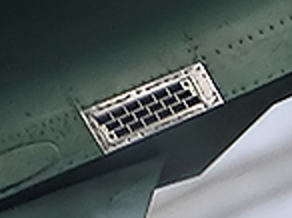
I also think, that the two small round things are just crews to hold the bucket there - can also be seen on chaff bucket. This one sgingle picture is very very questionable and its origin also. We even dont know, if the flares come from that plane. Most questionable is, why there is no flare light effect on vertical stabilizer what so ever. This really could be fake. I found more photos of exact dispencer layout as can be seen in DCS JF-17 (1"x2" flares at the bottom and chaffs at upper side of tail fuselage). There is non of photos or public videos (at least what i have found) that show different layout from that in DCS. The chaff decoys are not size of 1"x1". The shape is more rectangular. Like I estimated before: 1"x1.5"

-
M206 and MJU-7 are not same performance. M206 is no more than 60% effective as MJU-7. Thats also why even now the A-10C II is using both type flares. M206 in wingtip dispencers and MJU-7 in discpencers behind main gears. Not dierct proof here but usefull data from its sister and brother made by CHEMRING company: Flare CM 218 Mk3 Type 1 - MJU-7 equivalent https://www.chemring.com/~/media/Files/C/Chemring-V3/documents/countermeasures/updated datasheets/conventional flares/58500_Issue_8.pdf Flare CM 118 Mk3 Type 1 - M206 equivalent https://www.chemring.com/~/media/Files/C/Chemring-V3/documents/countermeasures/updated datasheets/conventional flares/58550.pdf Just how complicated is world of only western made flares is depicted in folling article: https://www.armadainternational.com/2021/09/airborne-deception/
-
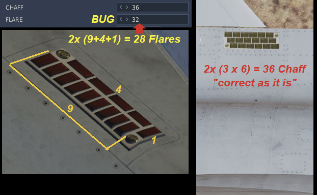
The FLARE seem to be same size as MJU-7 1x2 inch - max total number is 28, no more. Chaff is different size, seems like 1x1,5 inch (according to texture pixel measurement) - max total number is 36, which is correct in DCS editor. Due to different size of countermeasure and very different dispencer, it highly unlikely to have Chaffs and Flares interchangeable. If you find and post here detailed pictures of real JF-17 with its dispencers, you will see tham Im correct.
-
Simple mathematics:
-
 I would like to add to already reported (MAG show TRUE and vice versa), not fixed bug the addition of Offset point not showing in correct possition on SA page - sometimes showing wrong bearing and sometimes even range. In track bellow mark position on SA page is nicely compared with TACAN radial (WP1 is located at LSV 12X TACAN position). Hornet_offset_BUG.trk
 -
What is missile v_min and v_mid speed???
GumidekCZ replied to GumidekCZ's topic in How To Mod for DCS World
Really? Sorry, I muse laugh . Because you last of your two post just tell us very well known things. Like that Earth have not exact shape of spehre. -
What is missile v_min and v_mid speed???
GumidekCZ replied to GumidekCZ's topic in How To Mod for DCS World
You posted nothing new ... just description from same lua script which Im trying to understand. If you want to help, try to explain it in more detail, ... what calculation use these values, how it affect the missile performance, if... -
Please, can somebody explain me what v_min and v_mid speeds means in missiles script? Is the v_min stall speed, or speed trigger for self-destruction? v_mid speed? Average speed, what, where? From time of start to hit? Thanks for meaningful reply with good explanation
-
[Report Thread] Bugs of China Asset Pack
GumidekCZ replied to RocketmanAL's topic in Chinese Asset Pack
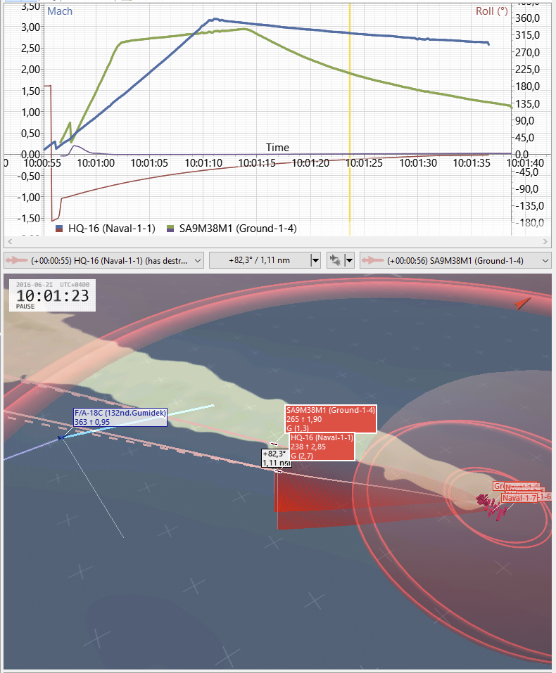
HQ-16 missile drag not fixed with latest patch , but its performance even more boosted with decreasing LowSpeed limit and improving chaff rejection coefficient. I also wonder where Deka get the missile life time. SA-11 missile in DCS 80 seconds, HQ-16 missile 180 seconds. This with help of above mentioned bug creates total UFO missile able to chase you down to almost 50nm away from ship, if calculated impact point is within its calculated lifetime. -
Any stick input on autopilot droops the nose downwards
GumidekCZ replied to Zaneboy's topic in Bugs and Problems
Same here, ... very annoying but. I hope, HB will fix this soon. -
Searching for proof of underperforming AN/APG-73 radar
GumidekCZ replied to GumidekCZ's topic in DCS: F/A-18C
Question, which may be rised here ... ,can ED contact JANES, may be pay a little sum and get the information about all DCS radar preformances (including may be new and more accurate APG-65 detections for FC3 F-15C). Or can somedoy do it for ED? -
Searching for proof of underperforming AN/APG-73 radar
GumidekCZ replied to GumidekCZ's topic in DCS: F/A-18C
Found this source of interesting radar detection capabilities gathered by JANES: removed link Dont forget to read first 2 pages. (Middle detection Range number is for RCS 5m2 - in DCS equals F/A-18C, F-15, F-5, AV-8B, MiG-29) ALL RANGES ARE IN NAUTICAL MILES! More can be found if you know the name of radar. Sadly, Janes does not mention specific versions for all radars. RCS [sq m]: ( 100 / 20 / 5 / 0.1 / 0.01 ) F/A-18C APG-73 ( 160 / 113 / 84 / 36 / 11 ) in DCS not 84 nm, but only around 47 nm. This is way more than ED giving us. With these values it makes sense of having 160nm radar scale. I think ED intentionaly reduced all radar ranges (NOT the 3rd parties like Deka) with aim of keeping DCS performance high and low hardware requirements. Data comes originaly from this page, but cant be reached for free or are restricted.https://www.janes.com/ I really would like to report this as bug, but I guess, because of above mention reasons, detection ranges will not change, no matter what. -
correct as is Awacs blindstops when orbiting
GumidekCZ replied to Mike_Romeo's topic in Aircraft AI Bugs (Non-Combined Arms)
Do the same blind spot appear with KJ-2000 Chineese AWACS with its AESA radar? -
FLOOD mode button missing when AIM-7 fired on L&S designated target -> automatic STT lock. FLOOD mode cant be selected on DDI. FLOOD mode button only able to select if AIM-7 fired on STT target. Second part of bug: - In many ocasions, FLOOD mode not guiding missile after selected on DDI or if second AIM-7 fired when radar already in FLOOD mode from previous AIM-7 launch. AIM-7_FLOOD_BUG.trk
-
investigating ALL IR guided missiles FLARE rejection inconsistency
GumidekCZ replied to GumidekCZ's topic in Weapon Bugs
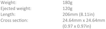
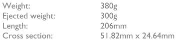
with connection to FLARE rejection, I found interesting scientific paper about small and big flare effectivness released from probably idle AMX jet and C-130. On top of that, the facts mentioned in that study just confirms the above mentioned bug. https://www.reddit.com/r/hoggit/comments/rwn11i/effectivnes_of_big_and_small_flares_in_scientific/?utm_source=share&utm_medium=web2x&context=3 Seems, that the effectivness of small FLARE as is in DCS (according to tests around 50% of the bigger brother) is unrated. Also according to papers from manufacturer the big one Peak IR output: 20kW/sr nominal and the small one has Peak IR output: 12kW/sr nominal - 60% of the big one. Big: 51.82mm x 24.64mm x 200 mm Small: 24.64mm x 24.64mm x 206 mm -
[Report Thread] Bugs of China Asset Pack
GumidekCZ replied to RocketmanAL's topic in Chinese Asset Pack
[CHK] Hi @uboats HQ-16 WRONG DRAG MODEL - MISSILE DRAG ALMOST NOT EXIST: Track: HQ-16_Drag_BUG.trk BLUE line HQ-16 - you can see that missile is not loosing its speed due to drag - but only by gaining altitude. Red line comes from SA-11 missile.
-
Unable select FLOOD mode for AIM-7 guidance manualy?
GumidekCZ replied to GumidekCZ's topic in DCS: F/A-18C
Im thinking that legacy hornet can be able to control FLOOD mode same as APG-73 equiped SuperHornet. https://forums.vrsimulations.com/support/index.php/Air-to-Air_Radar#FLOOD_Mode -
Can be real APG-73 target lock fooled by notch above horizon?, when no clutter behind and radar in that upper hemisphere can simply switch filter automaticaly off.
-
Im wondering, if in real Hornet, there was also none possible way to select FLOOD mode manualy, not just automaticaly after firing AIM-7 without the lock. Was the avionic so "simple", that after lost lock, there cant be FLOOD mode selected as in M2000C? where it is automatic.
-
Why AIM-7 cannot be guided anymore, after target relocked after loosing it for even just a second?
-
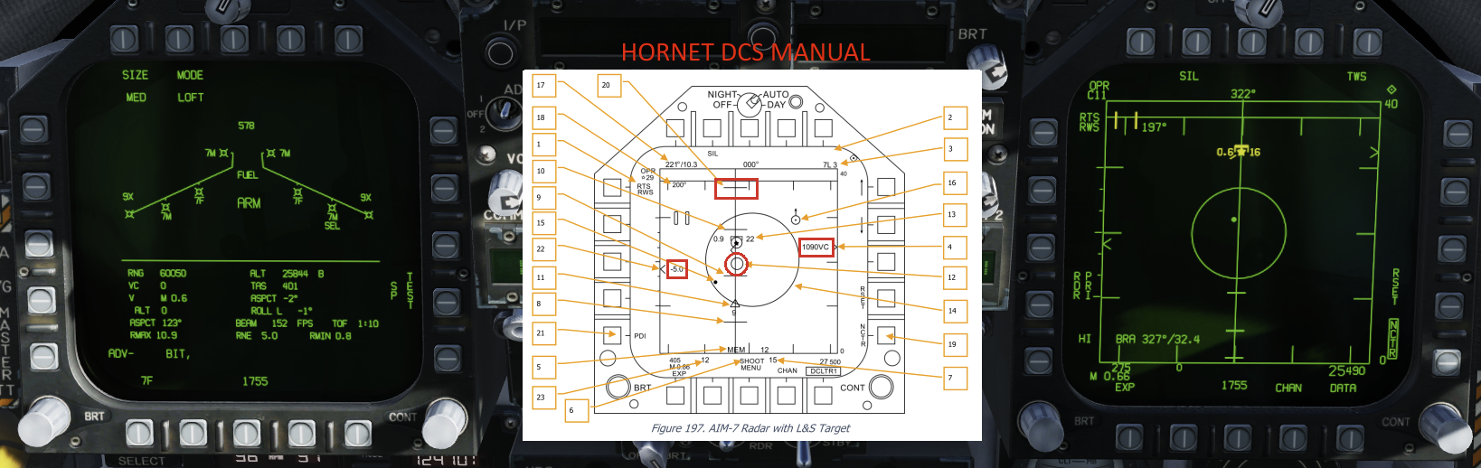
w.i.p Missing radar information with AIM-7MH (LOFT) selected
GumidekCZ replied to GumidekCZ's topic in Bugs and Problems
Thanks, You are True about Target Altitude Differential and Closure Rate values, but RLOFT and AIM-7 Max Seeker Range Cue is still missing. -
As name of this bug says - Missing radar information with AIM-7MH (LOFT) selected. I tried L&S selected target or STT but it doesnt matter, it will never show info it shall according to manual. Hornets manual page 415: vs latest OpenBeta 4 - Target Range and Closure Indication 12 - AIM-7 Max Seeker Range Cue. 20 - RLOFT. Maximum range using a LOFT launch. 22 - Target Altitude Differential. Displays the difference in altitude between the target and ownship in thousands of feet.
-
+1 Like Gizzy said.
-
@Blinky.ben@okopanjaNothing what should change mine or anyone alse mind about reported RCS. Also this not something I want to discuss. I could use word "Affordable", but its just a game with words, nothing else.
-
That's a really not good idea, to take absolute different plane RCS class and do the same pixel technique. Somebody told you to do that, or you figured it out yourself? Next time don't forget also to color the radome. (Some new radomes have FSS (frequency selective surface) composite design, which actually absorb outer radar energy, but never by 100%. - I don't know if JF-17BL1 or F-16C-BL50 have it, I just red that JF has dielectric radome. So to be fair to both airframes, I colored both radomes.) I know this pixel technique is not accurate, and did that only to point out the very similar RCS F-16 vs JF-17.... nothing more, nothing less. This not a method for every airframe in DCS, but can lead te better estimations rather than just arguing around.