tavarish palkovnik
-
Posts
477 -
Joined
-
Last visited
Content Type
Profiles
Forums
Events
Everything posted by tavarish palkovnik
-
Semyorka and Soyuz are conceptually same, technics of 50’s, and fun fact, today’s astronauts Russians, Americans and others still lifting their “assets” in space using technology from 50’s because it is reliable, safe and without marketing exaggerations
-
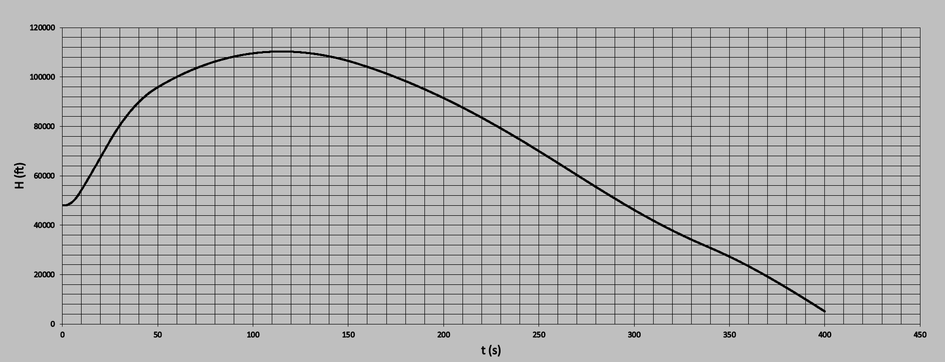
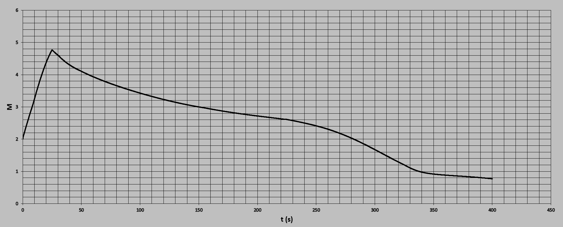
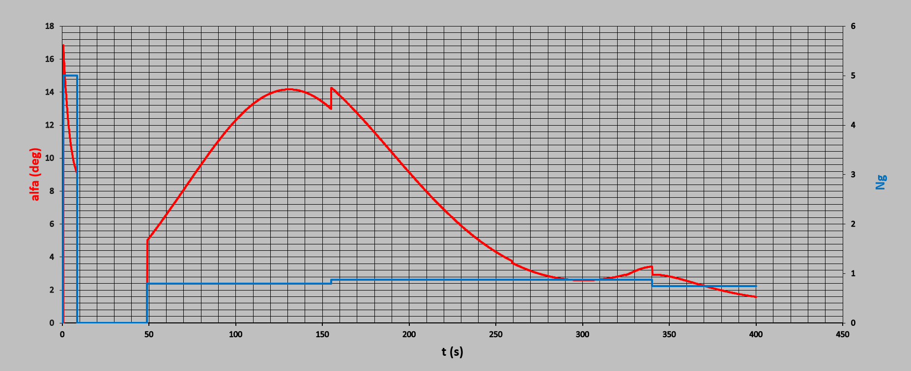
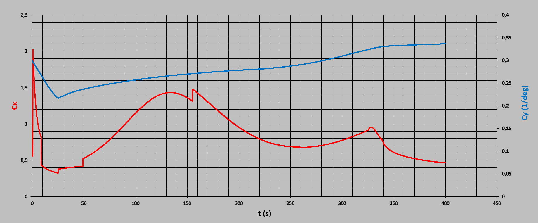
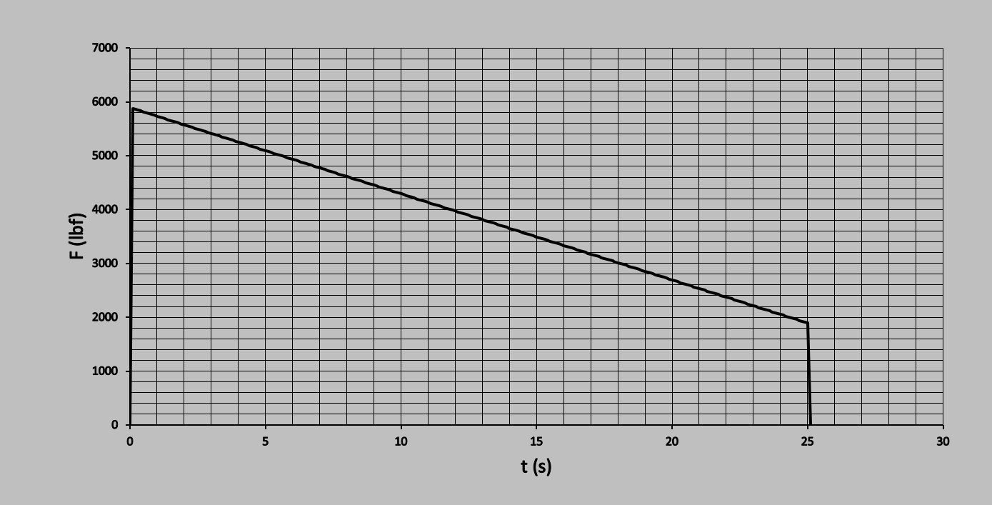
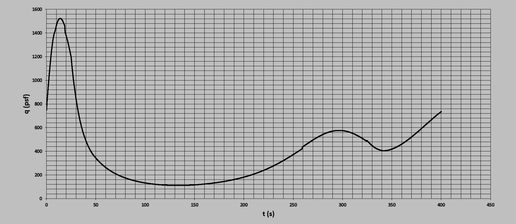
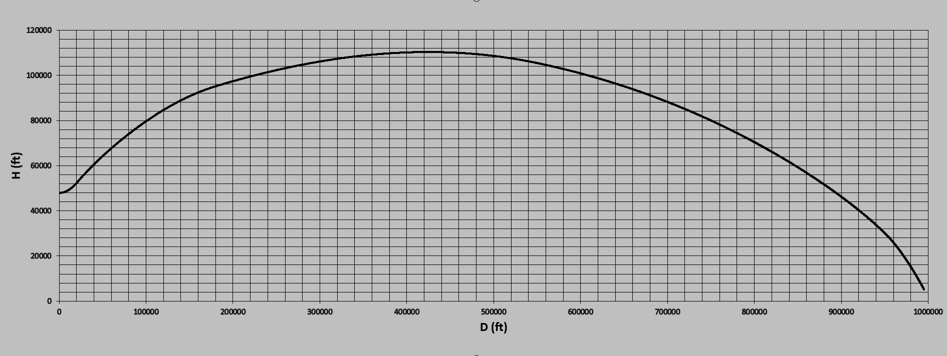
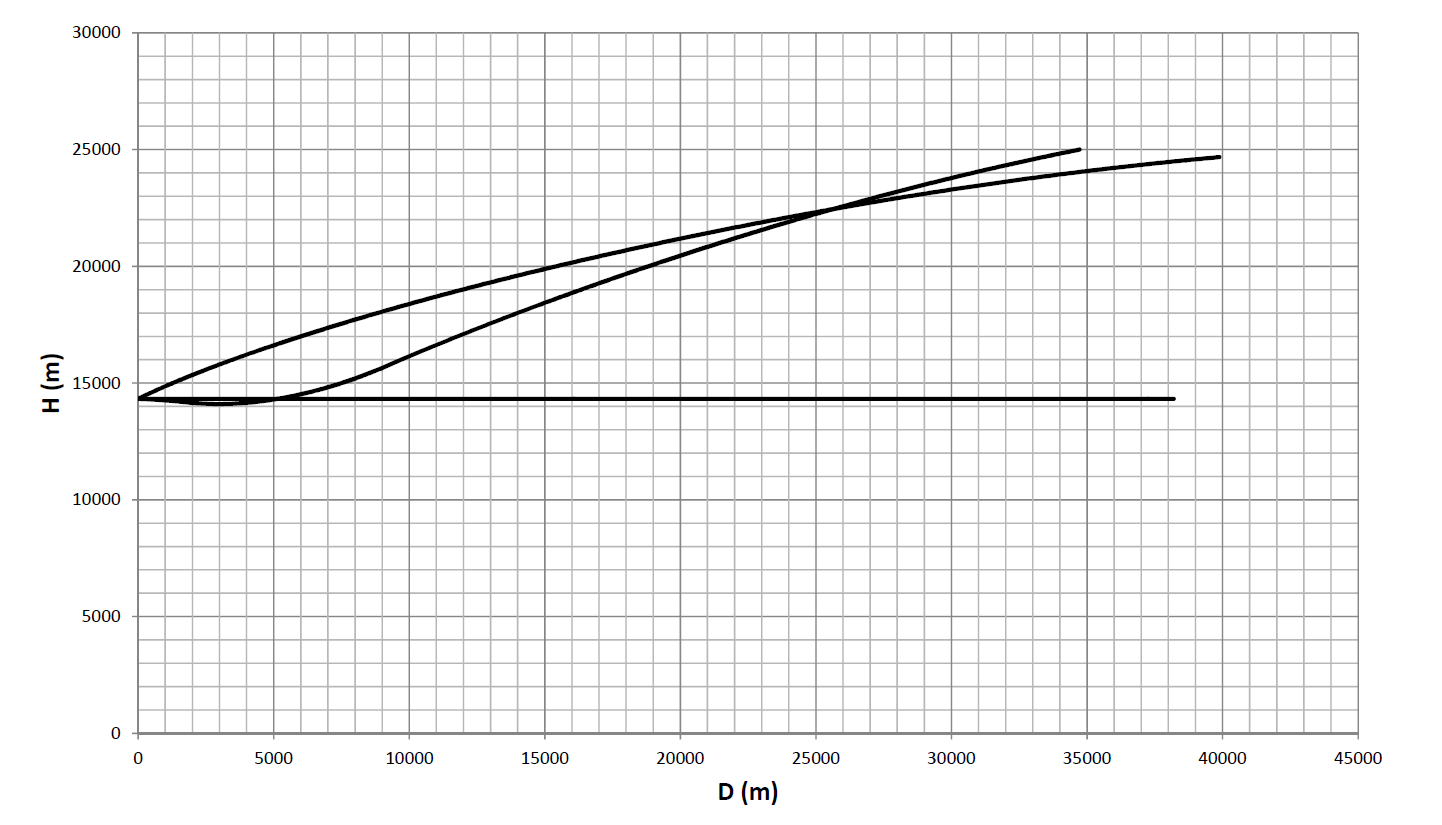
This one was tough but after several attempts I manged to get it flies that way It was all about when, how and how much to overload missile This is how Cx and Cy change with time Motor of course is not Spoonge Bob form but more as it should be This is change of dynamic pressure with time And at the end how trajectory looks like Of course this has nothing related with original Phoenix, NASA planned to use it for other purposes.

-
Thanks @draconus for time and efforts. If you manage to find some extra time, try to make this exact shot and I’m pretty sure there should not be some significant or any loft. I know in game lot of things are simplified, when I make some specific trajectory I put “in machine” program which makes integrating of mostly all mutually linked factors…and missile simply doesn’t like to go in loft.
-
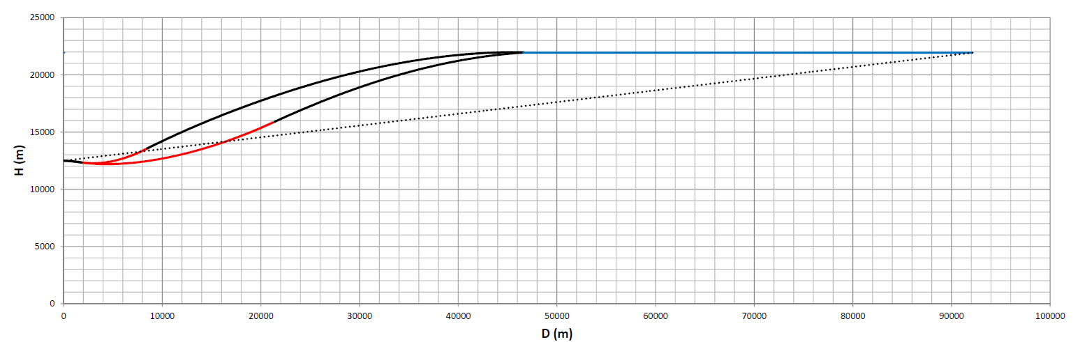
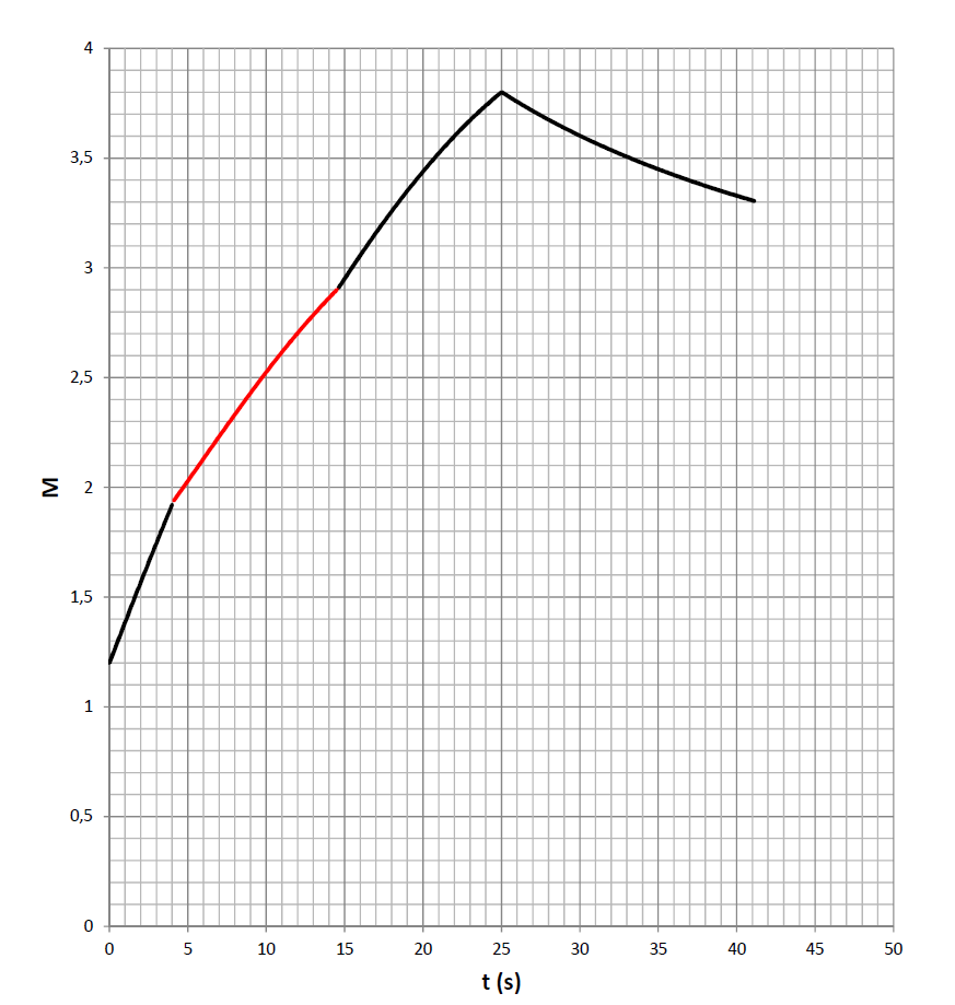
We didn't understand each other well, these shots of mine are not shots with elevation (airplane pitch) but shots from horizontal fly and red parts of trajectory are parts where missile is overloaded, missile performs loft alone by its energy as it should be. Also this sample you made is not case we have. Launch range is 50nm (92,6km) , distance between fighter and target in moment of launch. Shot range in that case is something about 25 nm (46km) measured from starting point and that for me is point of launch. It is fligth time for missile of only 55 seconds or something like that
-
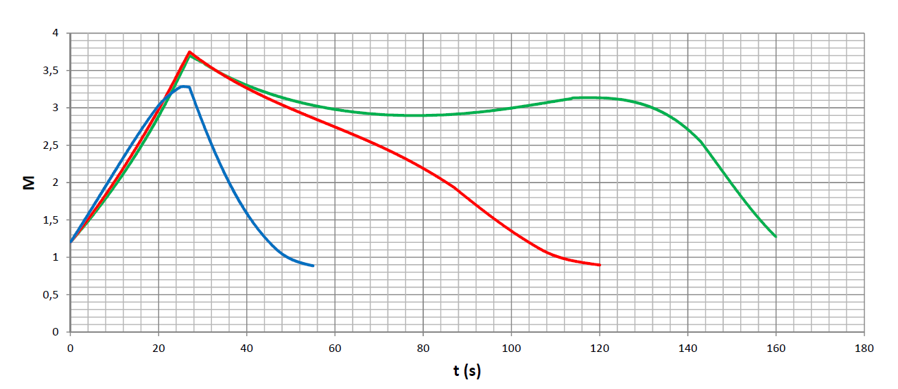
I will try to explain, with my poor English, this last scenario. This is loft, actually attempt to loft over such quick approaching target (in 55 seconds target travels 45,5 km). This starting 5g overload up there could be boundary condition for AIM-54, like said it is starting 25 degrees angle of attack for missile. Theoretically with overload >5g missile could in this scenario go over target altitude, with significant velocity shock performing such maneuver. And that is not all, to avoid situation that target slips under, missile should perform one more overloaded maneuver, now with negative angle of attack which will take additional velocity potential. Two such maneuvers will result with terminal velocity for sure less than managed 2,8M as presented. Eventually, if airplane will be in moment of launch with some elevation angle relatively to horizon, and by that missile in start will not need to handle with initial pushing nose from downward to upward, having starting elevation angle in opposite direction to what loft is looking for. And honestly, I’m not sure airplanes like F-14 made real launches of missiles like AIM-54 at such altitudes flying overloaded, flying with height gain, flying with axis elevated relatively to horizon. If this scenario would be with target flying a bit lower than these 22km and slower than these insane 2,8M, missile would go with this 5g in visually full blooded loft. However, these two sample shots are everything but not standard shots.
-
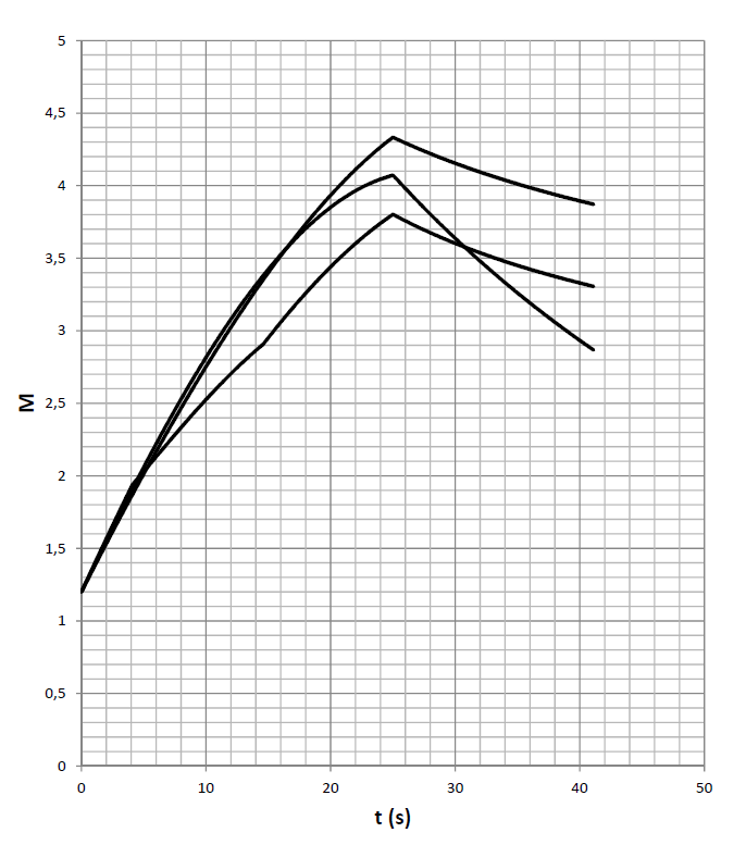
Another case, launch against super fast high altitude flying target In two options, overload with 5g and 3g, and all is to be better with higher/shorter overload. It is nearly (almost) same time untill contact but terminal velocity is higher with 5g becuase missile would take a bit less dense atmosphere
-
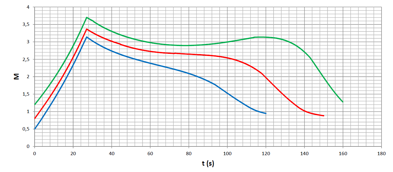
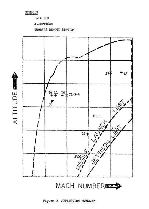
Is there volunteer to simulate this situation in-game to see how it behaves? Most probably it will be a bit, or quite, most likely, different because basic postulates are different. I didn’t mention, thrust envelope I’ve used is linear drop function from 26210 N (0+s) to 8418 N (25s) what makes total impulse of 432850 Ns or 97313 lbs. With drag coefficients I don’t occupy too much (don’t see those as over too much significant) so I always use Cx58 rule and for this situation I selected i58 as 1,2 for active and 1,5 for passive time (PS…numbers are not exact Cx numbers but factors relative to Cx58 numbers). And for lift coefficients in supersonic range, simple linear function (-0,03*M+0,26) Another case 72000ft/2,8M/50nm is also interesting as well as low flying target (Figure 10)
-
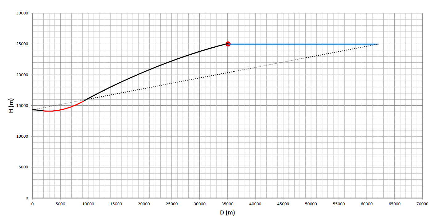
Check of mathematical model (with used like they wrote ''publicly available data'' , meaning here I used 13595 N / 27 sec), and comparison with famous NASA ''shots'' 45000ft ; 1,2M ; 0 / 30 / 45 deg 45000ft ; 45deg ; 1,2 / 0,8 / 0,5 M It fits nice, only this thrust envelope has nothing related with real condition
-
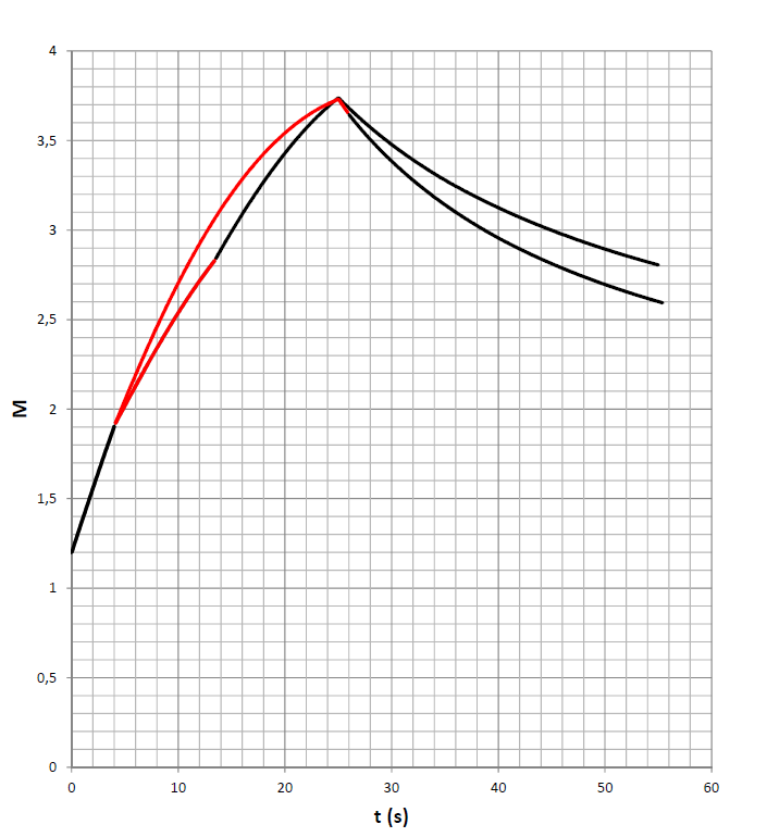
This is how I see flight as per Figure No.7 could looks like, targeting high speed/high altitude ''Mig-25'' Missile usually after releasing is with small decline relatively to airplane axis, I gave it as negative 2 degeess. Then first 4 seconds after motor started, missile released starts its flight, after that I overloaded missile with constant 5g. That is red part of trajectory, and than missile is again released. For velocity this overload has significant influence, 5g in 10 seconds is flight with angle of attack from 25 to 13 deg -> For comparison, three cases, this one, horizontal constantly overloaded flight and ballistic shot with start elevation 30 deg
-
I would take it as 0,4 M
-
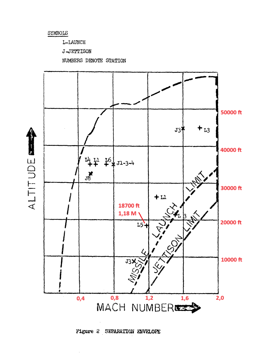
AIM-54 zone puska.pdf
-
...
-
...
-
...
-
Except, it looks nice
-
...
-
By the way, could be coincidence or maybe not…sustaining stage and 20,8 bar of chamber pressure together with expansion ratio 6,2 for heat ratio 1,2 suggest pressure at nozzle exit of 47300 Pa (0,473 bar) what is ambient pressure at 6000 meters or 20000 ft
-
...
-
Yes that is Omega, and yes orbital speed how I call it, is angular rate of the line of sight. However, it is speed and speed can be constant, with acceleration or with retardation. Only here it is not m/s but deg/s. In circular (but really circular) motion target with constant velocity around point is with constant orbital speed. If angle like in case of this last declined 45deg trajectory is with every new second bigger and bigger, then it is orbital speed which is with acceleration, positive sign. It is not about clockwise or against clockwise when speed is matter, only about kind of speed, acceleration or retardation
-
...
-
...
-
Can you make some sketches, for example on these 3 cases, it will be easier to follow and to understand. How you would position missile’s inertial navigation trajectories chasing these targets