DummyCatz
-
Posts
194 -
Joined
-
Last visited
7 Followers


Recent Profile Visitors
6056 profile views


-
 Hi, it's been quite some time since the first half of the F16 SEP fix has dropped (as well as the proposed F18 FM rework), and I'd like to know what is the current progress of the remaining fixes? In addition to Full Afterburner SEP, MIL power SEP are also worth checking based on other user's feedback.
 -
For instantaneous g-load, Yo-Yo said that DCS does not consider non-steady-state flight dynamics (e.g. dynamic changes in lift coefficient during rapid changes in angle of attack). It would explain why the value is lower than irl.
-
See also and
-
By switching to Take-off and Landing Gains, you essentially command pitch-rate with your stick, instead of G. And the FLCS will hold 0 pitch-rate (instead of 1g as in Cruise Gains) when hands off stick. This is beneficial to flying qualities at lower speeds (e.g. < 400 knots) so you can manipulate pitch-rate more precisely. The only difference in FLCS logic between using the AIR REFUEL button and lowering the gear is that, the AIR REFUEL button will not lower the flaps automatically.
-
@Harley Just tested with DCS 2.9.15.9408, the speedbrake-to-stabilator interconnect logic is still working at low speeds, which contradicts Function 100. You can confirm this by using active pause and then experiment with speedbrake commands at different Mach Numbers. In this case, the g-transient is purely caused by the FCS itself, and is a wrong behavior.
-
OP asked if there is a definition for the correlated degrees of travel that the pitch correction input from the elevons is supposed to be. I gave the answer. Sometimes NATOPS doesn't give the full picture. I'm not sure what you're trying to argue here. I am not the one who disputed the word 'Alleviate', as with all open-loop linear compensation logics. The point here is to provide an overall system description when NATOPS cannot be posted on the forum, and the fact that it only works in a limited range of Mach Numbers (high subsonic speeds). It can be inferred that the pitch bobble is not that pronounced in low subsonic speeds, where it doesn't require compensation by the FCS. Also, the interconnect command is on/off in response to speedbrake solenoid valve command, meaning it's either on or off in response to the opening and closing action, but not actual positions. This clarifies OP's doubt. The cited NASA report is for FCC OFP v10.1, and the logic should be the same from v10.1 to v10.7 as there's no documented change in speedbrake-to-stabilator interconnect function.
-
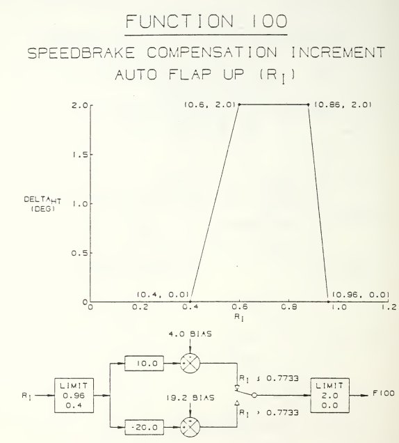
According to the NASA Technical Memorandum 107601 (https://ntrs.nasa.gov/citations/19920024293), a speedbrake-to-stabilator interconnect (Function 100) is incorporated to alleviate g transients for speedbrake extension/retraction. The interconnect command is on/off in response to speedbrake solenoid valve command. The magnitude of the input command air data scheduled. The interconnect command is lagged through a first order low-pass filter with the time constant scheduled with air data and as a function of speedbrake extension or retraction. The speedbrake extend time constant is less than the speedbrake retract time constant. The schema of Function 100: In which, Ri (pressure ratio) = dynamic pressure / standard atmosphere pressure. As you can see, the delta HT (horizontal tail) compensation is only active in a range of Ri from 0.4 to 0.96, which roughly corresponds to 0.7 - 1.1 Mach. Other references: https://www.semanticscholar.org/paper/Development-of-a-mathematical-model-that-simulates-Rojek/0fde51d56d310669dd67ae8520a0650989a91156 https://archive.org/details/developmentofmat00roje/page/n3/mode/2up distribution unlimited.

-
There has been a pitch creep bug that is related to the issue you described and is still being investigated.
-
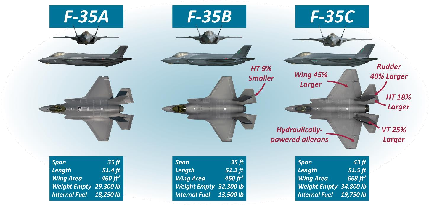
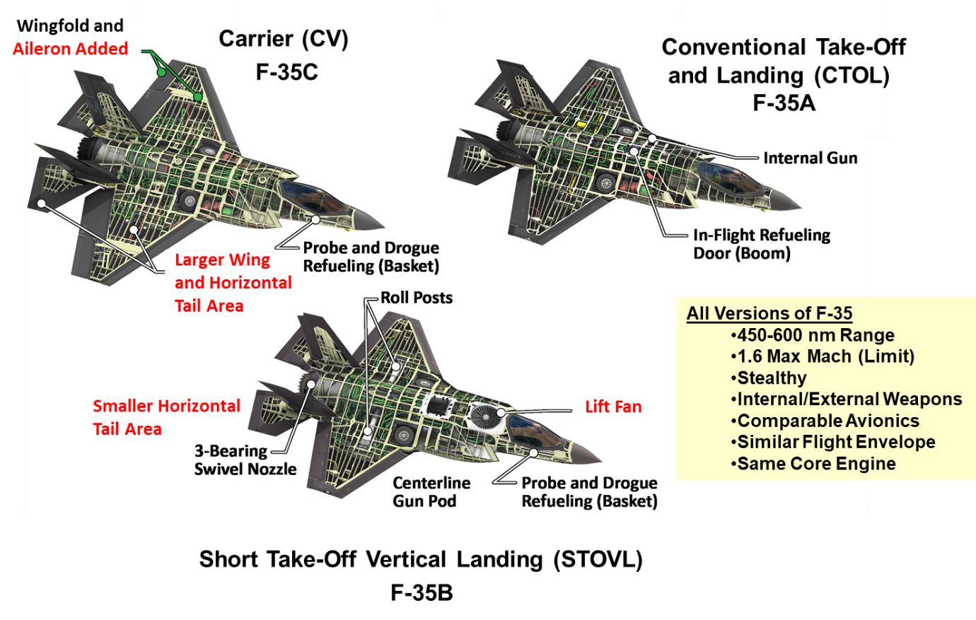
According to the public papers by Lockheed Martin, the aerodynamic differences in wing area and horizontal tail surface area among the versions, and the differences in basic stability and control power, are not trivial. Designing control laws for three versions at the same time, without standing up independent development teams, required creative approaches in order to meet program schedules. That's why a unified model-based, dynamic inversion approach using auto-generated code is chosen. This technique eliminates the need to linearize the aircraft system at specific flight conditions and develop extensive gain schedules, which is a time-consuming process in a more traditional FBW design. Instead, it allows designers to directly specify the desired aircraft response, accommodating the nonlinear dynamics of each variant. It adapts to aerodynamic, control surfaces and propulsion differences, through an onboard model (OBM) rather than requiring entirely separate control laws, ensuring similar flight characteristics and meeting program efficiency goals. But still, here are some interesting unique FM differences: The F-35C is less prone to deep stalls (same as those experienced by F-16) compared to the other variants, even in worst-case conditions. This is due to its larger horizontal tail, which contrasts with the STOVL variant’s higher susceptibility to deep stalls due to its smaller tail, and the CTOL variant’s weak deep stall potential only at extreme aft center of gravity (CG) positions with low fuel. On the other hand the F-35C posed the most significant challenges in departure resistance (the ability to resist uncontrolled flight departures). For example, During a test maneuver, the aircraft experienced a rapid, uncommanded roll reversal due to adverse sideslip, aggravated by its unique features like aileron deflection, increased wing span, and the proximity of the wing and horizontal tail. This was addressed with control law (CLAW) modifications and updates to the aerodynamic onboard model (OBM). At around 0.75 Mach and near stall AOA, the F-35C exhibited poor sideslip control during maneuvers, leading to larger-than-desired sideslips. While control was maintained, CLAW updates and additional low-altitude testing were implemented to mitigate potential excessive loads. The F-35C showed unique anomalies at lower altitudes (e.g., below 20,000 feet), where errors in Mach-dependent coefficients became more pronounced due to higher dynamic pressure and slower deceleration rates. This necessitated additional testing down to 7,000 feet MSL, unlike the CTOL and STOVL variants, which did not exhibit similar issues. The extra effort ensured the F-35C was cleared for unrestricted high AOA maneuvering at all altitudes. Just some examples. Fig. 1 of https://arc.aiaa.org/doi/10.2514/6.2018-3516 (F-35 Flight Control Law Design, Development and Verification) Fig. 2 of https://arc.aiaa.org/doi/10.2514/5.9781624105678.0525.0574 (F-35 High Angle of Attack Flight Control Development and Flight Test Results)
-
High AOA after making a loop when below 280 KTS
DummyCatz replied to TunisianRaptor's topic in DCS: F-16C Viper
This is caused by inertia coupling and is recently introduced, so deep stall is more likely to happen. Have you tried pitch rocking technique? -
investigating New FM, pitch oscillations on supersonic speed
DummyCatz replied to Blackfyre's topic in Bugs and Problems
Depends on the progress of the mentioned FM/FCS refactoring. -
What's the procedure for a crosswind landing?
DummyCatz replied to Hyperlynx's topic in DCS: F-16C Viper
The beta (AOS) feedback in the DFLCS is not functional in take-off & landing gains. -
That’s interesting. Might need to test 1g SEP at low speed too, to see if the fix caused discrepancies in other part of the diagram.
-
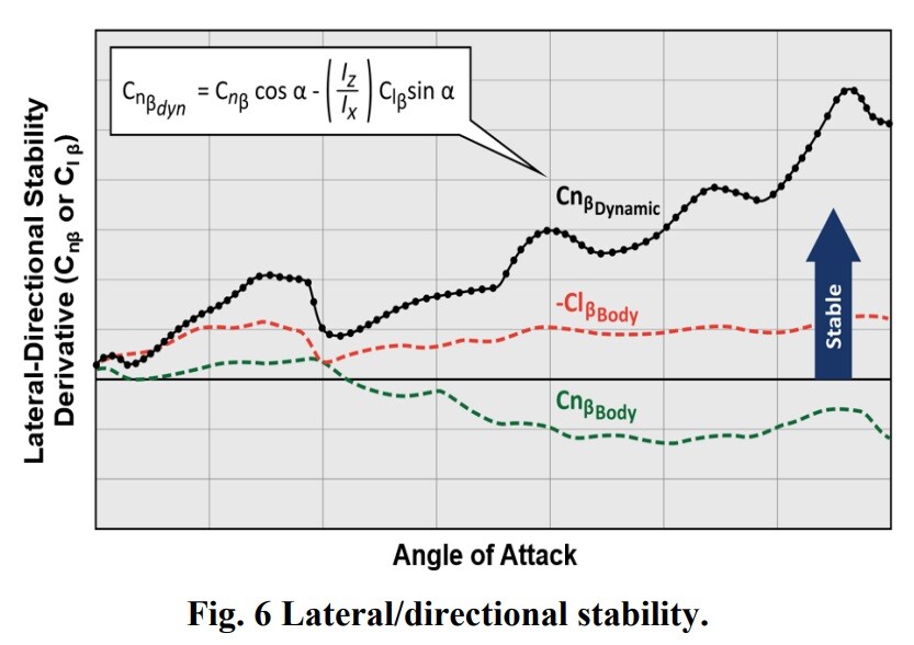
Regarding the notion of deliberately hiding classified aspects of high AOA modeling - this would be detectable. Flight dynamics are deeply interconnected, and any artificial limitations, inaccuracies or simplifications would create detectable inconsistencies. Knowledgeable users can identify these discrepancies using publicly available information, as demonstrated through existing flight model bug reports that rely solely on public sources. (e.g. some of my F-18 FM reports.) The core challenge remains implementing both the complex high AOA aerodynamic modeling with its asymmetric moments, and the NDI-based flight control system. However, we do have some useful reference points. The AIAA papers provide stability derivative and control power trends (Cm, Cn, Cl diagrams) that, even without absolute values, still reveals the general shape of those coefficients of aerodynamic moments. So we can know the relative control effectiveness and aircraft static stability across AOA ranges. For example the lateral-directional stability derivatives of the F-35 from Fig 6 of the AIAA paper quoted above, that you know when the Cn-beta dips into negative values, the AOA should be somewhere around 25-30 deg. What makes this particularly interesting is how the NDI system essentially defines the aircraft's maximum allowable performance envelope. We know the system aims to maximize performance within safety boundaries, prevent departures while minimizing interference, and deliver consistent handling qualities. This suggests that if you can accurately model the basic aerodynamic behavior using scaled/estimated data from public trends, as well as the NDI control architecture's fundamental principles with departure prevention and departure recovery modes, you could potentially achieve a reasonable approximation of the aircraft's actual performance characteristics, since the NDI system would naturally optimize control within whatever envelope you've defined. While exact values remain classified, the general behavior and performance could be reasonably reconstructed through careful implementation of the documented NDI principles and known aerodynamic trends.
-
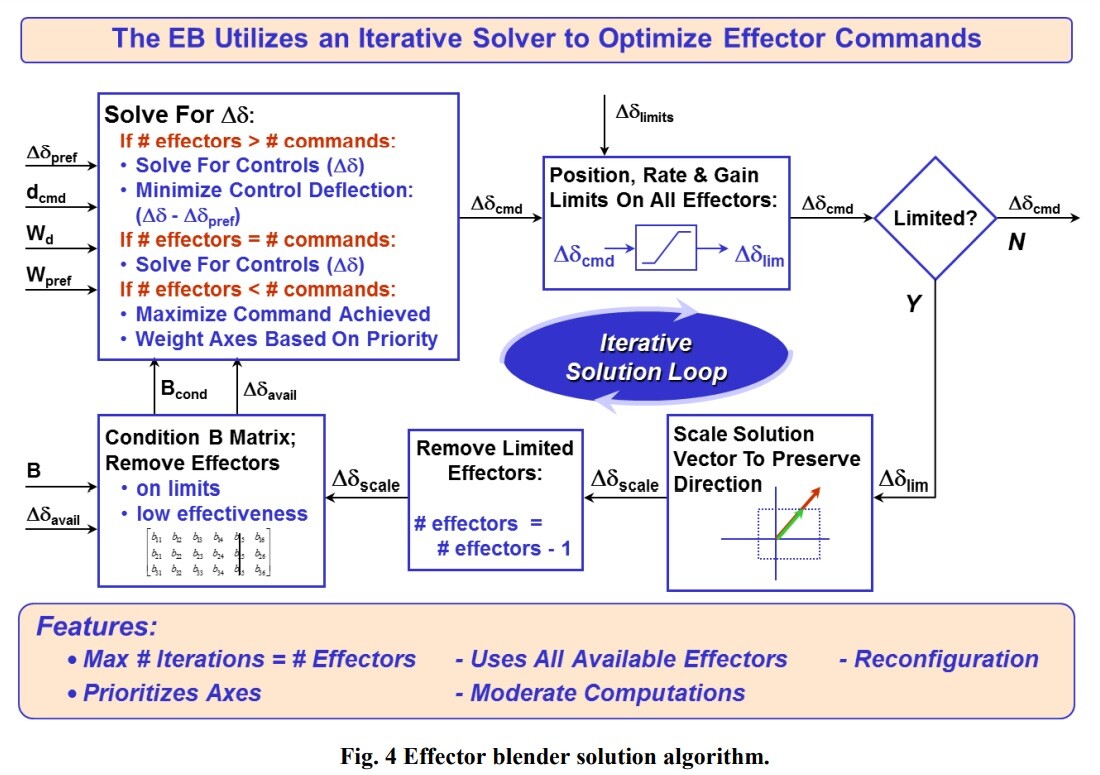
Thanks for the excellent write up. The F-35 IRL is indeed using INDI, as the engineers had to deal with significant challenges from onboard aerodynamic model (OBM) mismatches, especially in high AOA as well as transonic regions. In DCS, you could theoretically have a naive NDI system using the exact same aerodynamic model that's driving the simulation - creating a perfect match between the OBM and the simulated aircraft behavior. This would be "cheating" in the sense that it eliminates one of the fundamental challenges that makes real NDI implementation difficult. But this raises some other interesting questions about simulation fidelity: Should ED deliberately introduce model mismatches to more accurately represent the real system's limitations? Could using the same model for both simulation and control (OBM) make the aircraft behave more like an idealized mathematical model than a real machine, so that the handling characteristics is in a way unrealistically and overly optimistic, with the resulting control allocations being too "precise" that doesn't match the real F-35's handling qualities? The most computational cost probably comes from an iterator, like the pseudo-inverse iterative calculation of the Effector Blender (EB), as explained in https://arc.aiaa.org/doi/10.2514/6.2018-3516 Compared to the traditional control surface mixer, whose control logic will only be running one time per simulation cycle, the EB logic will be running several times per simulation cycle, due to the iterative solver. It will indeed be cool to see how ED will handle this.