Super Grover
-
Posts
326 -
Joined
-
Last visited
-
Days Won
1
Content Type
Profiles
Forums
Events
Everything posted by Super Grover
-
@some1, thank you for your messages. We're here to provide the most realistic simulation ever, yet, of course, we understand the needs of the users who value more of the gameplay aspects and have fun with the module on their rules. We will look for a solution enabling you to tailor the force feedback response to your needs. However, please note that using such settings may degrade your experience with the module, as it may create centring forces that are not present in real aircraft.
-
Thank you for your message, Selliese. The GIF you posted demonstrates correct and intended behaviour. You start by pulling the stick, and this causes the aircraft to increase the angle of attack. The increased AoA translates to a G-Force build-up. The F-4 has a bobweight attached to the pitch controls, and the force (moment) of the bobweight is proportional to the G-Force. The more G, the more the neutral stick position gets displaced forward. In other words, the bobweight always acts as if it wants to return the aircraft to 1 G. When you released the stick, the G number was still high, and so the neutral position was displaced forward. When the aircraft unloaded, the neutral position returned slowly to the original position before the entire manoeuvre. Unfortunately, I don't know the details of the F-5 that well to compare it with the F-4, so I don't know if the observed behaviour is correct. Usually, I'd be eager to understand that myself and to share that understanding with you; however, the responsibilities related to the release prevent me from dedicating time to that - I'm sorry. Nevertheless, if you find the answer yourself, you may share it with all of us so we can learn some interesting details about the F-5.
-
I am sorry to disappoint you, BMS, but I'm quite certain that you don't want that to happen as this would cause an effect similar to the problem which some of the users experience when one of their non-FFB controllers report as FFB-capable, and they have to disable it in the options. Effectively, this wouldn't let you use the trim, and the aircraft would have a nose-up tendency as the middle of the available stick deflection range is equal to the stabilator position of 7° leading edge down.
-
I might have been imprecise in my words. In real aircraft, the friction forces are pretty high (and above the threshold to open the gate inside the force transducer for the pilot stick). However, we can't simulate them because that would disconnect your physical stick input from the aircraft controls position, and it would be highly disorientating for you. However, we had to find a way to make the stick stay around where it should be when you're stationary - so we enabled another slightly simplified model when stationary, which prevents the stick from falling fully forward. We spent a lot of time understanding and modelling the flight controls system, including the bellows and the feel trim. This allowed us to prepare a physical model for the neutral stick position, where the net force from the feel trim system is zero. This position is the centred position for the non-FFB sticks and the zero-force position for the FFB sticks. However, on the ground, this position is often beyond the physical limits for the aircraft stick position - which is exactly why we have that special on-ground mode. The options to disable force limits and force blending are for non-FFB users who, for any reason, prefer a more "traditional" relation of the joystick position to the aircraft stick position. Yet, I'd try to convince everyone to try force blending first. This is 100% correct, and we modelled the pitch controls to include all those elements: the bobweight and the bellows. The point where the forces (moments) from these two cancel each other is the neutral stick position.
-
The stick position in the cockpit when stationary on the ground isn't directly related to your physical stick position, as high friction in the real aircraft cannot be applied when combined with the joysticks we use. Stick force limit and stick force blending are applied only to non-FFB joysticks and ignored for FFB joysticks. Their purpose is to emulate more feedback from the stick for non-FFB joystick users. Pitch stick forces vary greatly with the airspeed in the real F-4 and are considered weak below 250 kt. For more detailed information, I recommend reading this report: https://apps.dtic.mil/sti/citations/AD0881743 The AFCS breakout deadzone for the pitch axis only applies when using the AFCS mode (autopilot). It has no effect in all other states.
-

[Bug] [2.9.5.55300] Gamecrash after Loading F-4E Cockpit
Super Grover replied to Dynamis's topic in Bugs & Problems
I'm sorry that you experienced crashes with the module. Thank you for the logs - I'm sure they will help us find the cause of the issue. We will make sure to fix it as quickly as possible. -
It's better than that. We have @Cat107. We ship him in a box, and when we open the box on the other end, we know cat's state. Or something similar.
-
It's "smart" , so it should only happen when a state change needs to be synchronized.
-
I'm sorry, I hope it's better now. It's the codename for our core library/tech managing all components and their communication.
-
Hello everyone, My name is Krzysztof Sobczak (some of you may know me as “Grover”), I am the Technical Director at Heatblur. Although I haven't been very involved in direct communication with our users because I have been focusing on working hard on our projects, today, I am excited to share some technical insights about our latest release. As some of you may read from me for the first time, I'll start with a short introduction: I am originally a physicist holding a PhD in particle physics. However, most of my professional life has been dedicated to developing flight simulations. I have had the privilege of working with companies like A2A Simulations and Metrea. In 2018, I joined Heatblur Simulations to work on the F-14 Tomcat. During this project, my areas of responsibility included the communication and navigation systems, the LANTIRN targeting pod, and JESTER LANTIRN. In 2021, I became the Technical Director to create a new core system - codename Anvil - a genuinely new-generation simulation platform. Having been involved in creating several flight simulation engines throughout my career, I have gained a deep understanding of the requirements for such engines and the shortcomings of existing solutions. This extensive experience has been invaluable in shaping the form of our new flight simulation platform, which we present today through the release of the Heatblur F-4E Phantom II. Our users may already be familiar with the innovative approach we applied in the F-4E Phantom II, particularly the concept of the components system. For those with programming experience, this might initially sound like a marketing trick, similar to object-oriented programming and using objects through composition in different contexts to build complex structures. However, there is much more depth to the system we created. Our approach goes beyond simple object composition and reuse. What sets our system apart from other solutions and programming techniques is its orientation around data flow. This focus is crucial for creating a system that is both reusable and granular enough to build entire aircraft and reuse components in other aircraft or systems. The challenge in making such a system lies in the uniqueness of many aircraft devices, so to achieve true reusability, we had to reach deep to a level where components can be generalized - the level of individual switches, relays, lamps, amplifiers, actuators, valves, and all other kinds of low-level components. By focusing on the components and the data flow between them through the connections, we managed to move all non-simulation elements outside the components and let Anvil handle them. The first core aspect of our F-4E Phantom II, driven by our engine, is its multi-crew capability. The component connection approach allows our developers to focus entirely on creating the simulation part of each component. At the same time, the system handles the communication between different components and distributes it over the network. From the developer's perspective, there is no difference between developing an aircraft simulated entirely on one computer and an aircraft whose simulation is spread across multiple computers. The second feature unlocked by the component system is multi-threading. By strictly separating components from each other and not allowing them to access other components directly, we ensure that the simulation part of each component can run concurrently. This approach means that developers do not have to worry about the complexities of multi-threaded development and can work as if the simulation of each component were entirely single-threaded. The connection system governs the rest — it de-conflicts multiple simulation threads seamlessly. It is important to note that while our system is designed to support multi-threading, this feature is not enabled in the version that users are receiving today to limit the risks of the adverse effects for the premiere of such a complex aircraft. However, multi-threading will be enabled in future updates, offering a significant boost in performance for everyone. Also, note that this is not the same as using the multi-threaded version of DCS - the multi-threading part of our component system adds another layer of parallelization, effectively offloading the aircraft simulation from the main DCS thread. The component system is oriented toward providing developers with the tools to create new components quickly and efficiently. With those tools, we can focus on recreating components' real-life properties and giving them an organic feel by adding imperfections, individual characteristics and failures that can occur as a natural result based on the treatment of the components. Later, we use those components as bricks to build the aircraft in a fully synthetic way, while Anvil makes each airframe unique and each flight a new adventure while giving virtual pilots an incentive to not mistreat the aircraft. Finally, we plan to use Anvil and the same library of base components in all our future products, retrofitting them to the already published products where applicable. Sharing the same code will ensure that all our future aircraft will be automatically updated with our latest achievements and changes introduced to the system while developing any new product. This means that from now on, our simulation can only get more profound and more realistic. After introducing key features of the component system, let's delve into some statistics about DCS F-4E Phantom II. The total count of components used in our simulation, as in the final build provided to Eagle Dynamics, is 6,389. We used 14,627 component connections. Out of these, 2,297 connections are synchronized in multi-crew. The total number of properties across all components is 34,964, with 25,032 of these properties synchronized in multi-crew. Many of these properties are randomized and depend on the wear and condition of the aircraft. Finally, the total count of all damaged states in the aircraft is 1,562. While this number is already high, we plan to implement many more new failures during the early access period. Some of you might be concerned about the costs of creating detailed products like our F-4E Phantom II, which could negatively impact the entire market. We never intended that, and we are confident this won't happen. First of all, our goal was to make the development of complex modules less expensive by improving the reusability of the code and offloading most of the low-level and repetitive development to Anvil, which will handle it automatically. Furthermore, we are part of the flight-sim community and want the study-level flight simulation to thrive. From the first days of this new platform, we shaped it in the form of SDK, which we want to offer our partners. This includes the entire library of components and JESTER. We believe that cooperation and fostering synergies is more creative and profitable than non-amicable competition. As you will be able to experience the F-4E Phantom II for DCS yourself, I hope you will enjoy every minute spent in our recreation of this magnificent aircraft. On behalf of the entire team, thank you for the support and excitement you express daily through all communication channels. Have fun!
- 55 replies
-
- 181
-

-

-
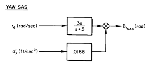
I thought that to give you more context, I could share an example of what is the level of detail at which we work when we model and code the aircraft. Let's consider the AN/ASA-32 Automatic Flight Control System, on which I worked together with @Cat107. In one of the documents published by NASA and publicly available, you'll find this formula: We managed to identify the resistors and capacitors responsible for that 0.5 damping factor - and actually, it's not precisely 0.5, but if you round it to one decimal digit, it will be. However, we don't model separate RC elements in the code, and we represent them as a single 'canceller' component with a transfer function - just converted to a discrete one - as in the diagram. This yaw rate canceller, together with a pitch rate canceller, and multiple other (electronic) devices such as servos, synchros, amplifiers, relays, switches, rate gyros, accelerometers, and power supplies, forms what is designated as AN/ASA-32. I think the step between an RC element and individual resistors and capacitors is where we want to draw the boundary of our component simulation. Finally, as I wrote in another topic that is now gone, we are open to sharing the tech with our current and future partners, which also includes benefiting from access to the constantly growing library of components.

-
The answer to the question is a bit complicated. Currently, there are no servos in the HUD code, but this is because the HUD code is one of the oldest parts of the simulation and requires upgrading to the latest standards. However, we try to implement individual parts, as shown in the diagram, including individual servos, whenever possible and if it adds any value to the simulation. It also means that the HUD will be upgraded to this standard sometime during the EA period. It's worth mentioning that since all our modules will eventually share a common library of components, any updates will be automatically available to all of them. This means that whenever we improve the simulation of a servo, such as adding more details or new failures, all devices in all aircraft using that servo will get automatically updated. This effectively means that our plan is to keep the modules updated with the latest technology even beyond the early access period.
-
@hermes7226, thank you for your feedback. We don't access any input device directly - every input we receive comes from the DCS API. I mean that, from our point of view, every joystick axis is the same. Could you send us your log file from the F-14 with your vjoy, please? Have you informed Eagle Dynamics about the issue? Of course, if there is any type of bug preventing you from using your vjoy, we will do everything we can to fix the issue.
-
As previously mentioned, a separate development report is required to fully cover the system of wear, damage, and failures. However, I would like to address some points to clarify potential misunderstandings. Firstly, when we began the F-4E project, we decided to establish a stable foundation that could be shared across all Heatblur modules. As a result, we plan to transfer new features to older products, starting with the F-14. However, this process may take some time. Secondly, we aimed to create a flexible and extensible system that could be developed and maintained for several years. We even considered future potential base simulation platform development scenarios and ensured that we could utilize their full potential in our product. This means that there are some features that cannot be implemented in DCS currently but may become available later, even beyond the early access period. One of the key features is the ability to save and restore the state of each component and the entire aircraft at any point. Yes, this means that persistent airframes in various forms are technically possible. However, we need to better understand how to blend it with gameplay features for the best user experience before we can promise anything. Our aim with these systems was to create realistic, immersive, and entertaining experiences for all users, whether they are casual or hardcore. We considered all use cases, including those in the competitive scene, and welcome feedback to ensure our products are enjoyable for everyone. Each feature comes with various settings to allow you to adjust them to your liking. Now, let's move on to the technical details, which I have listed to make it easier to follow. We use general terms like 'wear', 'condition', 'property' and 'failure' to abstract information about the aircraft. Still, their precise meaning is interpreted at the level of each component individually. As mentioned in the trailer, the F-4E is a collection of thousands of components. Each component is unique and has its own set of properties. Two components at the same level of wear will be slightly different. Some examples of how those properties can manifest in the aircraft: two tachometer gauges may have different accuracy; two pumps may have somewhat different effectiveness; pressure at which a check valve opens and closes will be different from valve to valve; etc. Each component accumulates wear independently. The rate at which it wears out may depend on various factors, such as extreme forces or temperatures. Each component has an assigned condition/quality. This value represents the combined quality of manufacturing, materials used, and maintenance. Component properties are affected by wear and condition. Wear and condition can be assigned per airframe by the mission creator. Components may fail, and each component may fail in multiple spectacular ways. Failures are an additional layer to the wear layer. Wear and other factors, such as damage from weapons, extreme forces or temperatures, may impact the moment when a failure occurs. Failures can be gradual; for example, a seizing-up motor or actuator may, at first, require higher forces to move and eventually stop altogether. Failures are NOT rolling a dice every second. However, we take into account all available sources describing what is the rated lifetime and approved failure rates. The total number of already defined possible points of failure in the F-4E is counted in thousands. Last but not least, if, for any reason, you want to deactivate all of the above, you can select 'reference aircraft' in the mission editor. Your F-4E will have all properties standardized, factory-fresh and in perfect condition. In summary, we wanted to make the F-4E feel organic and unique each time you fly it, and we hope you'll enjoy all the new features.
- 48 replies
-
- 23
-
-
-
I hope replays will work, unlike with the F-14
Super Grover replied to Katmandu's topic in DCS: F-4E Phantom
I fixed replays for the F-4 some time ago, and they work like a charm, yay! Sadly, it's not easy to apply the same fix for the F-14, so it will take some time before the changes are applied to the F-14. -
After posting, I realised the picture is a bit small. So I used zoom-enhance (I mean Gigapixel AI) and magnified it 3x with the default settings, so it should be easier to view on smaller screens.
-
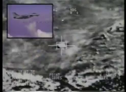
Oh, pixel counting - my favourite job! (Actually, I'm almost crying thinking about those hours spent measuring all elements of the LANTIRN display from the available videos.) So, this is tricky stuff because we have almost no footage of how it looked in the cockpit, and everything comes from the videos like the one above. I don't know how they got those recordings, but it seems like recording through a VHS camera footage played from another VHS device. I mean, the quality appears to be much worse than the original feed, everything much more blurry, not to mention the stretching from the aspect ratio difference. So definitely, nothing is blocky (even the symbology) because we're watching it through grease-covered glasses . It's so bad that I struggled with deciding if some symbols were single-pixel or double-pixel width. Finally, the shots from the EXP view are pretty rare. I guess the crews didn't enjoy the digital zoom (TBH, I never use it when I fly). But the Fighter Fling 1995 video has some, and I took a screenshot: It is blocky - the smallest squares are double the size of the font pixels. Ofc it's also very blurred - so much so that reading the text is difficult.
-
F-4E Phantom Development Report - DCS Newsletter 31/03/2023
Super Grover replied to IronMike's topic in DCS: F-4E Phantom
The plan was that the initial release version (non-DMAS) would be smokier, and the DMAS version would be the version after the upgrade, so the less smoky. OFC, everything is subject to change™ -
SA-5 Not Giving Launch Warning On F14's RWR
Super Grover replied to HeavyGun1450's topic in Bugs and Problems
Thank you for your reports. I verified the tracks, and the bug is not related to the SA-5 but to two tracking radars positioned next to each other. The tracks helped me find a bug in the RWR threat association algorithm, and it should be fixed in the next patch. Again, thank you very much. -
Thank you for your reports. GBU-24 bombs use a different type of steering/profile than the other laser-guided bombs available, and their time to impact depends heavily on the conditions when released and when lasing starts. We measured the difference, and we adjusted the calculated TTI to make the numbers closer to the bomb flight time when lasing immediately after the release. Also, we educated Jester to start lasing right after you pickle when using GBU-24. These changes should be included in the next update.
-
Lantirn/Lasing Issue With Certain Building
Super Grover replied to codyj007's topic in Bugs and Problems
Thank you for the reports. It's fixed internally and should be included in the next update. -
Thank you for your reports. I'll check it with the debug tools, and I'll get back to you when I know more about the reason for the freezes.
-
INS current pos update BUG (or FEATURE?)
Super Grover replied to Reactivator's topic in Bugs and Problems
Interesting, I'll take a look. I remember it worked when I tested queuing entering more than one waypoint, but it was long ago. I'll let you know about the results. Thank you. -
DMAS Version autonomous self lasing - Pave Spike / Pave Tack
Super Grover replied to AvroLanc's topic in DCS: F-4E Phantom
Yes, on the DSCG, I thought about the displays as that is how I understood the discussion above. The rest, I think, I answered in my first comment. Yes, we want the DSCG aircraft to have Pave Spike, and yes, we're thinking about Pave Tack for DMAS, but it's too soon to say that it's going to be there for sure. -
DMAS Version autonomous self lasing - Pave Spike / Pave Tack
Super Grover replied to AvroLanc's topic in DCS: F-4E Phantom
Both versions will be DSCG, but as far as I know, TISEO wasn't retrofitted to blocks 36-45. And the DMAS? I hate how the TISEO camera looks, but I guess we would never forgive ourselves if we didn't attach that ugly cylinder to the left wing.