whartsell
-
Posts
364 -
Joined
-
Last visited
-
Days Won
1
Content Type
Profiles
Forums
Events
Everything posted by whartsell
-
Arduino EOS Helios basic Tutorial
whartsell replied to whartsell's topic in PC Hardware and Related Software
I did some checking on this and it will only crash if you attempt to click and drag the slider. If you just click on a position on the bar or use the keyboard to scroll it will work just fine -
Arduino EOS Helios basic Tutorial
whartsell replied to whartsell's topic in PC Hardware and Related Software
I have also gotten an example SAS panel sketch created if anybody is interested. I figured it was a nice next step as it includes analog inputs,digital inputs and a LED output so it tests all the basics. I wont do a full tutorial but the sketch is well documented. If anybody is interested lemme know -
It was mentioned earlier in the forum (ill update my tutorial) that anything other than an UNO is untested. MEGAS are expected NOT to work due to the extra UARTS and such.
-
Arduino EOS Helios basic Tutorial
whartsell replied to whartsell's topic in PC Hardware and Related Software
In my (short) experience every time i touch the back light brightness bar it will crash. Ill have to think about it in terms of the boards. I like the matching idea as then you don't loose all your bindings. As it stands right now profiles are not easily shared as you have no idea what their board name or address will be. May also want to match on firmware as its the only immutable parameter in the Info command. -
i posted a quick tutorial on how to get arduino/eos/helios and dcs setup. Its a simple tutorial that walks through creating the Electrical control panel so it only covers digital inputs its located here
-
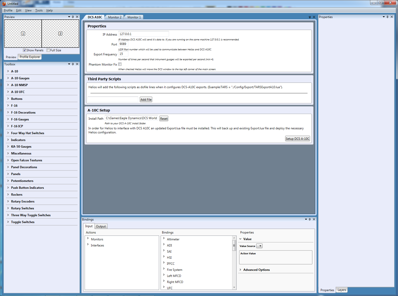
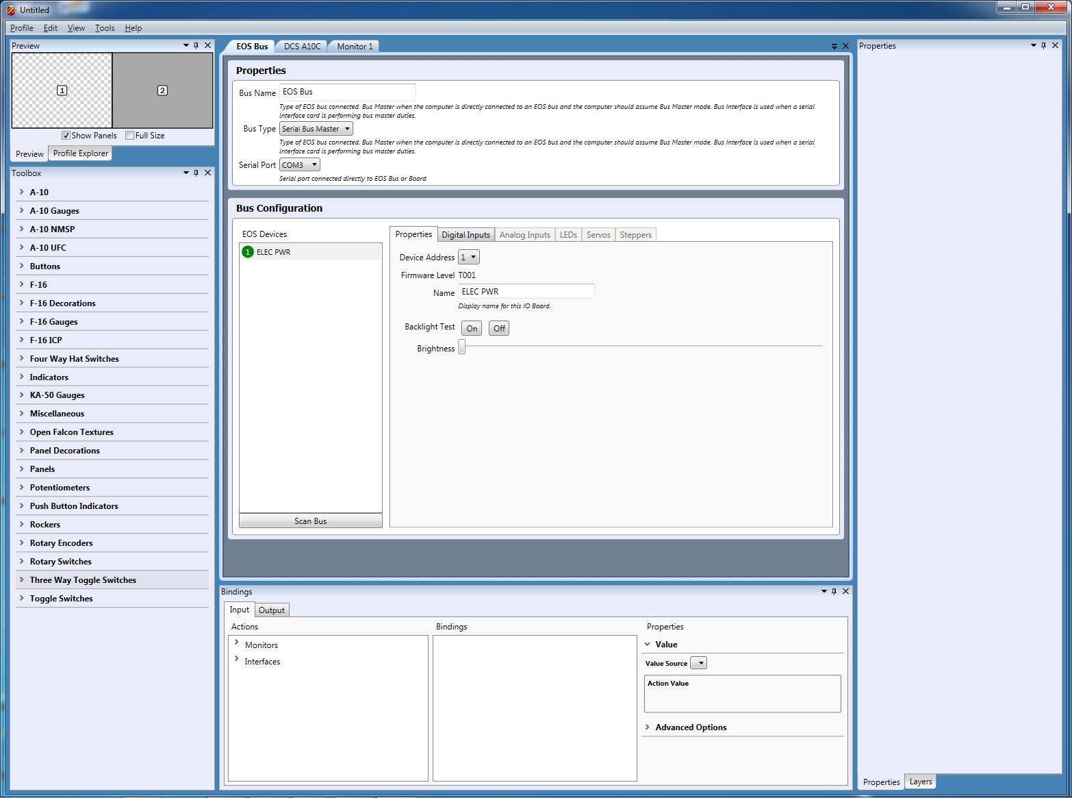
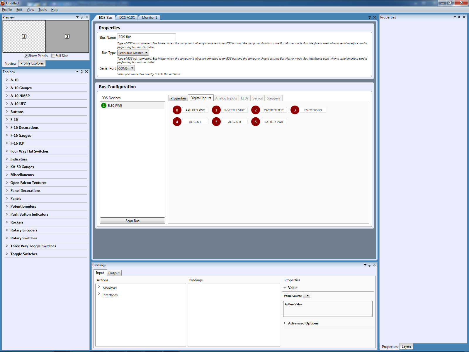
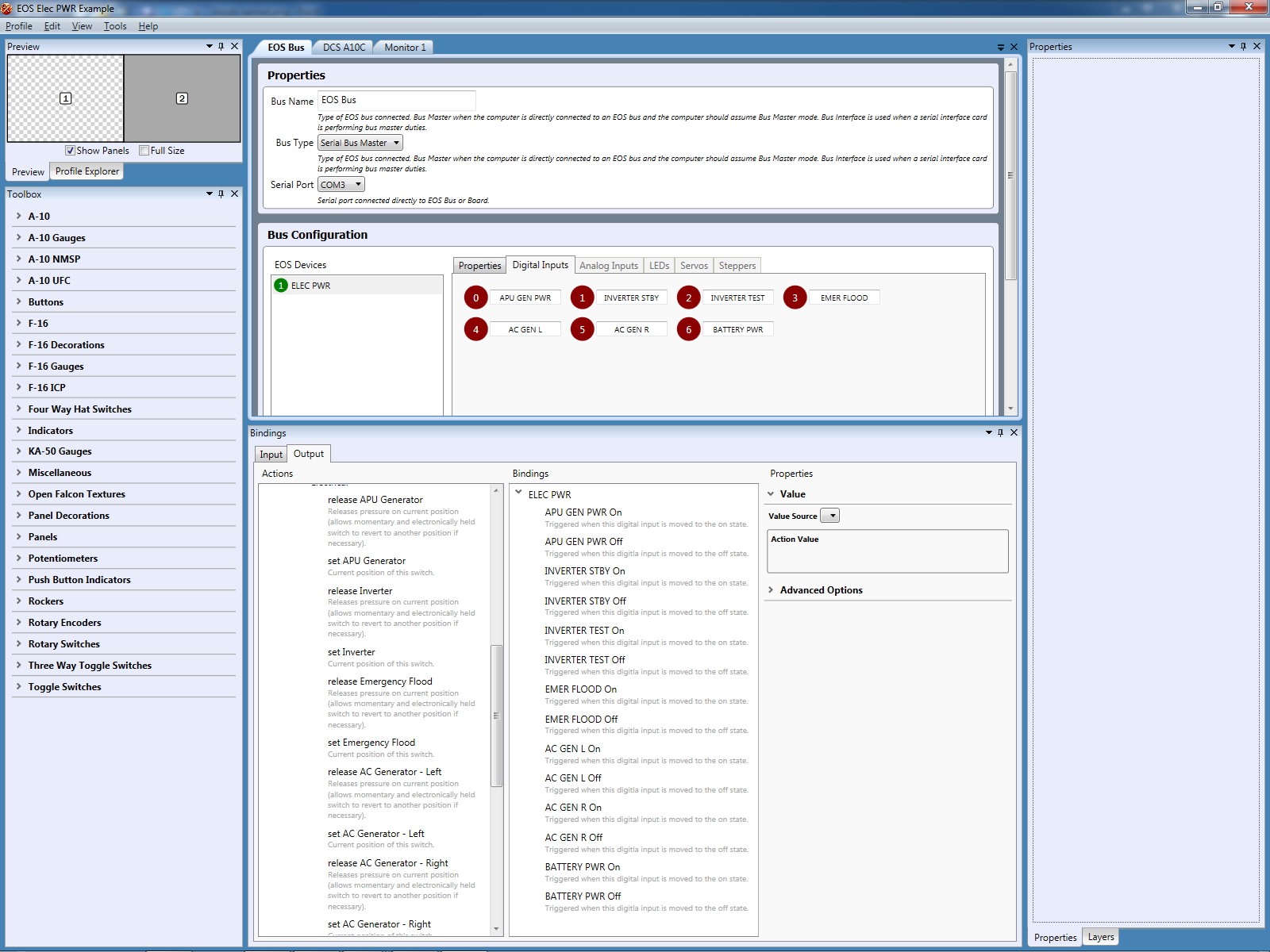
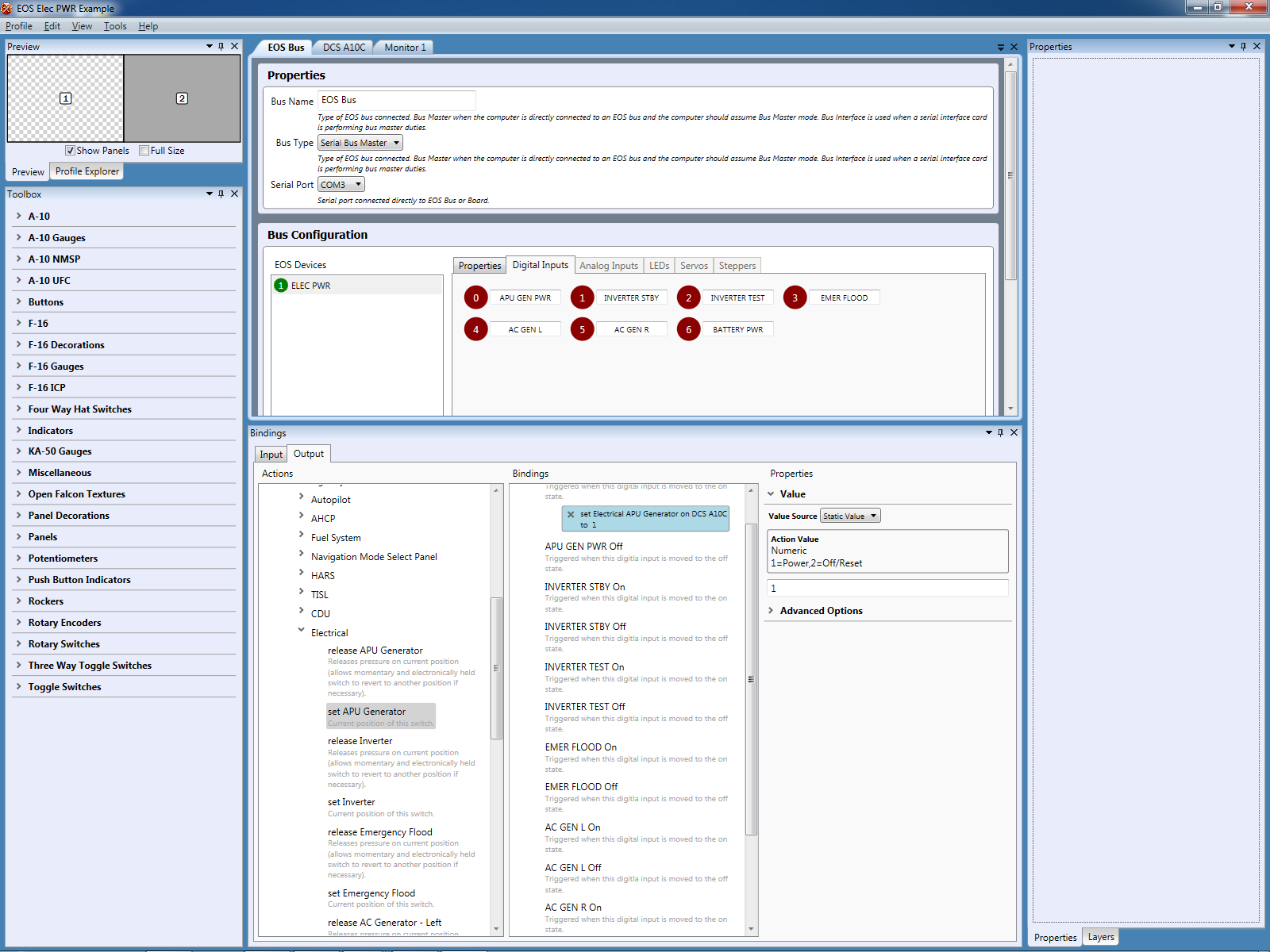
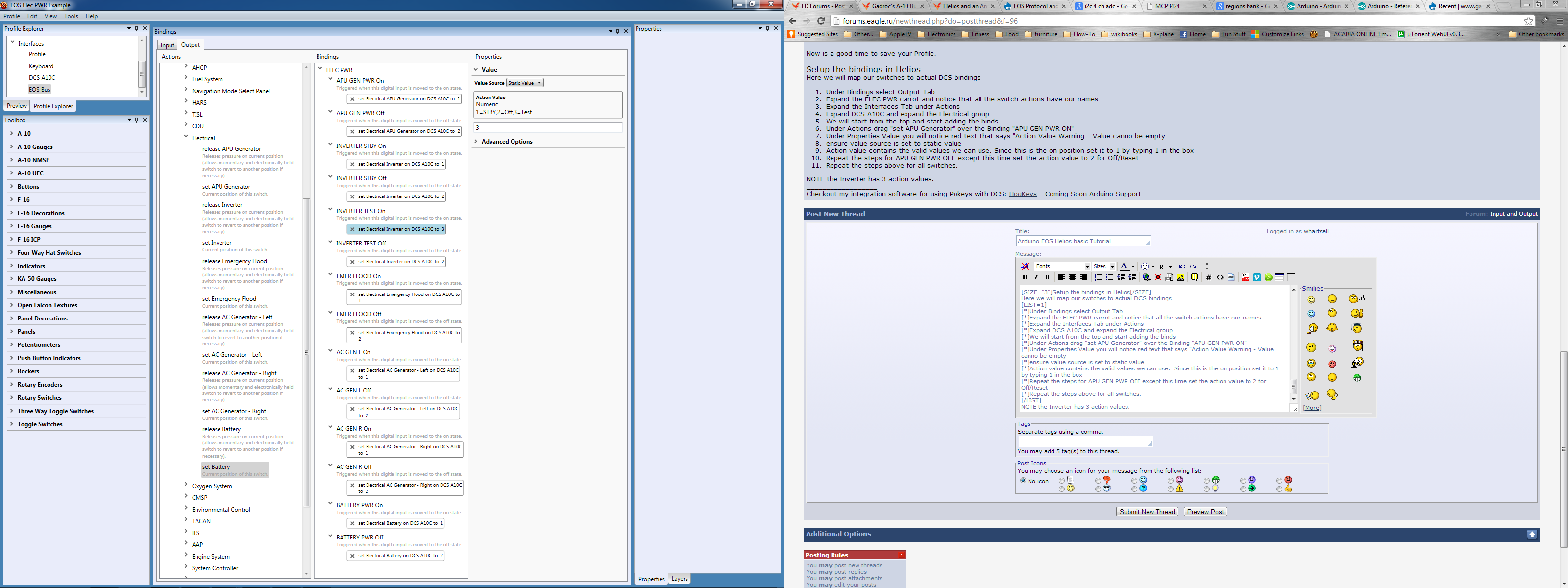
EOS and Helios Tutorial Update I have only tested Arduino UNO AND Duemilanove boards with EOSV1. MEGAS will NOT work. Leonardos most likely will not work. Others...your on your own. I believe that after testing an Arduino Duemilanove that all the 168/328 based boards should work fine as all the internals are the same. Yesterday I noticed that Gadroc released the latest EOS libs and Helios to support them. I played around with it yesterday and noticed that the learning curve can be a bit steep for the uninitiated so I figured I would right a quick tutorial on how to get an Arduino Uno up and running with EOS and configured in Helios as the Electrical Control Panel for the A-10. This tutorial will walk through all the steps required to get it up and controlling your A-10. Requirements Latest version of Helios Latest EOSV1 Libraries Arduino Uno and Arduino IDE. MEGAs will not work due to UARTS and EOS using low level serial control) ALL other boards are UNTESTED and expected to have issues Minimum 1 toggle switch wired to pin2 and ground on your arduino. Recomended 7 toggle switches each wired between pin [2,3,4,5,6,7,8] and ground on your arduino Initial Setup This Tutorial assumes you already have your arduino software setup and know how to download sketches to it. Basic Helios knowledge is assumed as there are better sources than me for the intricacies of setting it up. The attached sketch is verbosely documented which should allow you to understand whats going on. This example assumes you have a clean export.lua in DCS with no extras installed there. PLEASE do not deviate from this tutorial until after you have completed it and verified everything works. Ensure you have the latest Helios Installed Install the EOS libraries according to the included read me Download my attached sketch for the Arduino Installing the Arduino Sketch Clearing the EEPROM Since EOS uses EEPROM to store config data its a good idea to make sure all the EEPROM space is in a known state. Open The arduino IDE go to File>Examples>EEPROM>eeprom_clear Upload and run this sketch on your arduino Install the EOS_Digital_Input_Example sketch Open the Example sketch in your IDE Upload the sketch into your Arduino You can close the Arduino IDE now as we are finished with it HELIOS SETUP There are 3 main steps here Configure DCS Interface Configure EOS Interface Bind our board inputs to the A-10 Add DCS Interface Open Helios Profile Editor Go to Profile > Add Interface Select DCS A10C and click Add You can leave the defaults Under A-10 Setup Ensure it says "Your DCS A-10C configuration is up to date. If not click "Setup DCS A-10C" button Add EOS Interface Repeat the steps above, only this time select EOS Bus Under Properties ensure Bus Type is set to Serial Bus Master Select the Com Port for your Arduino The TX/RX lights should start flashing on your arduino. After a few seconds you should see "T01Board" listed under EOS Devices Configure the Board Click the Board listed under EOS Devices Set the Address to 2 (It appears 1 causes problems) Change the Name to ELEC PWR. NOTE the name is limited to 8 characters tab or click out of the Name box Notice that the address and name have been updated under the EOS Devices. This has been saved to the EEPROM on the Arduino and it will remember these settings on next boot To the Right of the Properties Tab click the Digital Inputs Tab You should see 7 digital inputs named Digital Input 0-7 Toggle each switch to ensure that the "button" turns from dark red to light red when on Rename the Inputs according to the attached pic Now is a good time to save your Profile. Setup the bindings in Helios Here we will map our switches to actual DCS bindings Under Bindings select Output Tab Expand the ELEC PWR carrot and notice that all the switch actions have our names Expand the Interfaces Tab under Actions Expand DCS A10C and expand the Electrical group We will start from the top and start adding the binds Under Actions drag "set APU Generator" over the Binding "APU GEN PWR ON" Under Properties Value you will notice red text that says "Action Value Warning - Value canno be empty ensure value source is set to static value Action value contains the valid values we can use. Since this is the on position set it to 1 by typing 1 in the box Repeat the steps for APU GEN PWR OFF except this time set the action value to 2 for Off/Reset Repeat the steps above for all switches. NOTE the Inverter has 3 action values. Save your profile once you have all the bindings configured Running and Testing your profile on my dev rig I run dcs windowed on a second monitor as its easier for troubleshooting. BE SURE YOU CLOSE PROFILE EDITOR BEFORE YOU START. otherwise when you attempt to launch the profile the com port will be locked by it and the profile will crash Launch Helios Control Center and select your Profile then click start. you should see your TX/RX lights flashing on your arduino Launch DCS and load an A-10 mission toggle your switches and you should see them working in the sim Gotchas..Issues backlight intensity will crash hellios...WORKAROUND dont use your mouse to slide the bar use keyboard only no way to remove a board from the interfaces. if you change your board address or name outside of helios (e.g on another profile) you will have to hack the hpf file to get it to work again if you change the name of an analog input your profile will become corrupted. Even hacking the hpf file will not fix it EOS_Digital_Input_Example.zip

-
I just tried out the new EOS libraries with an arduino Uno and it works great. Moving very cautiously it took be about an hour to get it setup and talking to the A-10. I hacked together firmware from your LEDBoard just as a POC. Hopefully ill have time tomorrow to gain a better understanding of the current library. If i get that done ill post a really simple poc tutorial with sample firmware so others can give it a try. If i get bored Ill check out what the level of effort will be for a Due as i have one of those laying around as well.
-
no worries...always happy to help. If you get stuck post the export and your scripts and ill review them. I do have bs installed on my gaming rig but no saitek hardware. I dont have bs installed on my dev rig though
-
correct...In the example above you split the (string) data that came in over the socket using "," as the token to split on. This results in a table. Then you take each item in the table and split the string using "=" as a token. The second element in that table is the value you would want to assign to whatever vars you use in your script. From a high level if you wanted to make it more robust (not sensitive to order) you could take each element in the first table and split the values into a key:value pair. This could be wrapped into a function that is completely reusable and wouldnt need to be altered when you add new variables. Then you could just look up each item you are interested in by the key and ordering would no longer be an issue. you also wouldnt need any local variables in that case as you could just use the key:values directly for example: instead of something like gear1up = value[2]... if gear1up == 1 then ... you could just have if data["gear1up"]== 1 then...
-
here is an example of how you could handle this situation. This does have the shortcoming of if the data order changes it will break.It is also not easilly maintainable for future expansion(adding a bunch of values). There are some more advanced ways to handle that and i can point you in that direction in the future if you require it I commented out all the saitek code cause i dont have saitek gear on this computer In short i added a function called StrSplit that allows you to split a string up into table based on a token. Every other step i took is commented in the code. lemme know if you have any questions/problems ----------------------------------------------------------------------------- -- TCP sample: Little program to dump lines received at a given port -- LuaSocket sample files -- Author: Diego Nehab -- RCS ID: $Id: listener.lua,v 1.11 2005/01/02 22:44:00 diego Exp $ ----------------------------------------------------------------------------- function StrSplit(str, delim, maxNb) -- Eliminate bad cases... if string.find(str, delim) == nil then return { str } end if maxNb == nil or maxNb < 1 then maxNb = 0 -- No limit end local result = {} local pat = "(.-)" .. delim .. "()" local nb = 0 local lastPos for part, pos in string.gfind(str, pat) do nb = nb + 1 result[nb] = part lastPos = pos if nb == maxNb then break end end -- Handle the last field if nb ~= maxNb then result[nb + 1] = string.sub(str, lastPos) end return result end -- require "saitek" -- saitek.AddPage("X52P",1,1, true); -- saitek.AddPage("X52P",1,2, false); -- saitek.AddPage("X52P",1,3, false); -- saitek.AddPage("X52P",1,4, false); -- saitek.AddPage("X52P",1,5, false); -- saitek.AddPage("X52P",1,6, false); -- saitek.AddPage("X52P",1,7, false); -- saitek.AddPage("X52P",1,8, false); -- saitek.AddPage("X52P",1,9, false); -- saitek.AddPage("X52P",1,10,false); -- Make and verify connections. --#################################################################### --#################################################################### local socket = require("socket") host = host or "localhost" port = port or 8080 if arg then host = arg[1] or host port = arg[2] or port end binding = (string.format("Binding'")) --saitek.SetString("X52P",1,1,1, binding) s = assert(socket.bind(host, port)) i, p = s:getsockname() assert(i, p) waiting = (string.format("Waiting" )) --saitek.SetString("X52P",1,1,2, waiting) c = assert(s:accept()) connected = (string.format("dcs Connected")) --saitek.SetString("X52P",1,1,3, connected) --##################################################################### --##################################################################### -- Recieve info --##################################################################### --##################################################################### while not e do if gear1up == 1 then --saitek.SetLed("X52P",1,1,11,true) print("gear1up on") else --saitek.SetLed("X52P",1,1,11,false) print("gear1up off") -- if -- gear1down == 1 then -- saitek.SetLed("X52P",1,1,12,true) -- else -- saitek.SetLed("X52P",1,1,12,false) -- end end --print(l) l, e = c:receive() print(e) data = StrSplit(e,",") -- we take the string received and split it into a table using , as the token to split the string on -- so altBar = somevalue, gear1up = somevalue, gear1down = somevalue, gear2up = somevalue, gear2down = somevalue, gear3up = somevalue, gear3down = somevalue\n" will be split into a table e.g -- gear1up is located at index 2 as lua uses 1 based indexing not 0 based indexing value = StrSplit(data[2],"=") -- now we split data[2] which contains gear1up=somevalue on the token "=" -- we now end up with value as a table containing "gear1up" at index 1 and the value as index2 so we set our gear1up variable to the value at index2 gear1up = value[2] end
-
Yes. Remember these are two seperate programs. One doesn't know what's in the other. When you send the data over the wire with the export you are sending it as one big string. On the client you will need to parse that strong to get the vues you are after Ill give you an example in a couple of hours. Im Currently maternity cloths shopping with the wife. Oh boy.
-
ok from what i see you are missing some code you send the data in the export ok (i wouldnt send the light states as float formatted strings but it will work). however your code doesnt actually do anything with the data once it receives it except prints it l, e = c:receive() print(e) This code block will never execute if gear1up == 1 then saitek.SetLed("X52P",1,1,11,true) else saitek.SetLed("X52P",1,1,11,false) if gear1down == 1 then saitek.SetLed("X52P",1,1,12,true) else saitek.SetLed("X52P",1,1,12,false) end as gear1up isnt defined anywhere. what you need to do is take "e" and parse out the values you want and assign them to a variable ...then you can act on it Im still at work but will check it out and write up an example when i get home. Also is there any reason why you are doing this with lua? or is it the language you are most familiar with
-
how are you formatting the data you are sending via udp?. If you attach the lua that is sending the data and an example of the actual data, I should be able to assist you. I also wouldn't mess with C++ C#/VB are a better choice. I use C# for my software
-
HogKeys A utility for using Pokeys with DCS A-10
whartsell replied to whartsell's topic in PC Hardware and Related Software
Nothing you can do at the moment. Im in the midst of getting 2.0 ready which will allow all those things in the future. Still got a few weeks of work left to get it all ready to go. The largest effort has been laying in the groundwork for a plugin based solution. I needed to do this to allow different hardware to work but the same principle will carry over to the simulator adapter and even input/output types. Once that gets done and stable then we can talk about getting other sims supported. Also once 2.0 gets some mileage on it I *may* provide a SDK to allow 3rd parties to add support for different hardware/simulators themselves. -
As great as the rasberry PI is it really isnt a good fit. It has alot of processing power but that really isnt needed. What really is needed is a good IO feature set for hardware integration which the PI lacks. Sure it has 27 GPIOs but only one can be used for PWM and none can be used for analog inputs. So in this realm of lots of inputs/outputs it really is less capable than the Amtel328p that the arduino uses. By the time you add the cost of expanding the PI to get the IO capabilities you could build at least 3 arduino based systems. Where the PI would be a better fit is in the case of using one as a dedicated controller for the CDU. The CDU has a bunch of digital inputs which can leverage the PI's GPIO and then you could do a little magic and make use of the PIs Display capability for the screen. Ethernet is also a nice feature that could be leveraged here as well. Another potential use of the PI would be to run all this integration software as a dedicated controller in the cockpit with all the add on boards connected to it. That way you free up all the processing on your simulator rig and don't need a separate PC to handle the integration. I have thought about this as a solution to free up PCs but in my case I would need to ensure compatibility of my software with MONO (CLR framework for linux as my software is .Net C#) and that is assuming MONO builds on PIs linux.
-
Yep. For me I have two goals. 1 I don't want a mishmash of different hardware. I would like as little variation as possible. As the variation goes up so does the complexity. 2. This is also a thought exercise so I want to learn as much as possible. I am a software performance engineer by trade but don't do a lot of real development in my job. With this project I get to combine my interests with my profession. I am learning alot about micro controllers, manufacturing, ui design etc. it also doesn't hurt that my previous profession was avionics in the military and volunteered restoring WW2 planes when I was younger. If you need any help with anything lemme know.
-
One more thing, with regards to implementing hardware/software for servos Pololu Makes a great servo board with up to 24 channels. If you don't mind using 3rd party and want an off the shelf solution. Their interface and API is incredibly simple to implement and would take all the design work out of your plans. Their boards are from 19-40 USD so they are pretty cost effective especially if you take into account R&D for creating a board and firmware. I have been thinking about getting one to play with
-
I agree completely with you. I started with the pokeys initially to remove one piece out of the equation. Since i was creating new software to interface with I wanted one known entity. If i had started with the arduino i would have been starting from scratch with unknown firmware,unknown hardware and unknown software. Now that I have confidence in my software and patterns the next step in the progression is the move to arduino. I was really excited for EOS but since its moving slower than me I wanted to make my own. My protocol is based "loosely" on the same pattern that EOS uses so when it matures my hardware could easily be upgraded to support that as well.
-
HogKeys A utility for using Pokeys with DCS A-10
whartsell replied to whartsell's topic in PC Hardware and Related Software
No near term plans for falcon BMS. The reason why I diddnt list it as its the one I have the least experience integrating with. It also appears a lot more complicated with its use of key callbacks instead of a single point of entry and offsets/index that the others use. I haven't looked at its shared memory documentation much but it looks promising. Either way its possible but will most likely be down the road a bit. -
i use the same chips for the digital and analog multiplexing. as for the pwm im partial to the PCA9685 as it uses i2c to control the pwm so you dont have to constantly pump data for pwm thus freeing up the processor to do other things. PCA9685 running 16 servos
-
Thats alot of hardware overkill for 80 inputs. If you use a switch matrix you can increase that number exponentially. with a "normal" arduino and one 3 8ch multiplexers you can get 96 switches in a switch matrix. That how i have been building things. Also for the price point of a mega I picked up a pokeys board. It has 128 inputs 7 analog inputs 80 outputs 6pwm and 16 7 segment displays. There are even some pins left for about 4/5 encoders. Of course that is configurable so you can change it to suit your needs but that is how mine is configured. For a full cockpit you will need about 330+ digital inputs,34 analog inputs 80 digital outputs and about 18 encoders. Thats not taking into account any customizations for cmsp and such. Switch matrixes while harder to debug when something goes wrong are great for easy of wiring and getting the most inputs vs actual input pins. I use ribbon cable with a 25 pin d-sub and it handles 128 inputs. plus you just "piggy-back" them. I ran the ribbon through each console and when i add a new panel i just crip an IDS dsub connector and done. with just two of those multiplexers you have you could easily build a 256 switch matrix and use only 8 pins on your mega. Once again latency would need to be measured but it should be pretty quick to send that data as it is only 32 bytes. Scanning it also be faster than your direct reading of 80 inputs most likely.
-
That's right. I'm just breaking them up into functionality. The two largest factors to consider are latency ( how long does it take to iterate through multiplexed devices) and how long does it take to cram that through a com port limited to 115k baud. Those two factors will determine how fast you can get/send updates to/from the sim. Also if your handy you can build your own arduino on a breadboard for about 8USD. That doesn't include the built in USB-serial port. What chip are you using for 16ch pwm
-
HogKeys A utility for using Pokeys with DCS A-10
whartsell replied to whartsell's topic in PC Hardware and Related Software
I am currently working on HogKeys 2.0. This is a major update and will allow for some really cool things like using arduino based hardware along with the current pokeys support. 2.0 may or may not include support for servos. If i don't get it ready in time 2.1 will include servo support. Planned Features: * New UI. The UI needed to be completely re-written to decouple it from the hardware. Im open to suggestions if anybody has any opinions on layout. Right now its based on what my needs are. This is taking the most time as all the "backend" functionality is basically unchanged (I built it right from the start). UI is not my forte. * support for Arduino based hardware (currently the poc is working and fully integrated) * implementing framework to support a plugin based driver/hardware model. This will make adding new hardware very easy. * implementing framework to support different simulators. Just like the hardware plugin model this will allow HogKeys to work with different simulators. e.g FSX,X-plane,etc * Servo support is coming (it may not make it into 2.0 but will definitely be in 2.1. Once 2.0 is done it will be trivial to add servo support. When a new input/output feature is added it will be hardware agnostic. This means that as long as the driver supports the feature it will be available. Currently pokeys supports everything you could think of. My Supplied arduino firmware will also be enhanced with the new featureset. The provided arduino firmware is meant to be a Reference Implementation meaning that it will work with the supplied reference circuits. You will be able to customize the arduino firmware (assuming you follow my api) to make it as specific to your application as you need it to be. The reference implementations will be based on what i'm using in my cockpit. I'm hoping to have 2.0 ready in about 2 weeks but that is subject to change. -
Good to hear. I have also been working on making my Hogkeys (pokeys interface for dcs) Software arduino capable. I have the POC completed and am no getting my software ready to handle the arduino. I have currently built working firmware for analog inputs,digital inputs,digital outputs and will be moving on to servos and steppers soon. My firmware will also be customizable to allow "custom" boards e.g one dedicated to UFC,CDU,etc. A single arduino will not have the power to do it all,Not to mention the data requirements of pushing it all out a single com port.
-
AI Messerschmitt Bf109E Beta released
whartsell replied to kato217's topic in Utility/Program Mods for DCS World
:thumbup::thumbup: Same here