Waxi
-
Posts
162 -
Joined
-
Last visited
Content Type
Profiles
Forums
Events
Everything posted by Waxi
-
I am looking for the same information. Has anyone figured out how to export gauges via export.lua?
-
I am looking for the same information. Does someone have an answer?
-
Now I am undecided which version I should go for. Is the A-10 version already available? Personally, I prefer a more robust seat and accept the higher price and shipping fees.
-
Excellent. I would take a set of replica seat cushions as well but first I have to discuss this investment opportunity with my "financial department." :smilewink: I still have one more question: The seat shown on the pictures above has a mount for the ejection seat arming handle but the handle itself is not shown. Will the ejection seat arming handle be included in the ACES II kit?
-
Hey Flim, thanks your answers. The shipping fee of $150 to GER sounds reasonable. Do you also offer seat cushions for the ACES II? If so, what will they cost?
-
I know :smilewink: Film wrote that prices for his ACES II kit will start at $399. Hence I am wondering whether he will offer different variants of the ACES II kit.
-
Great news. I am highly interested and have some questions: Would you be willing to ship to Europe/Germany? If so, could you please estimate the shipping fees? My educated guess is that shipping (without packaging) to Germany is something around $100. What do you mean by "The Aces II will start at $399?" Does this mean that you will offer different variants of your ACES II kit? If so, what will be the differences and what will be the cost of each variant? Which kind of payments do you accept? Paypal?
-
These touchscreen-based glass cockpits simplify pit building a lot ;-)
-
Benchmark here (DCS World 1.2.4 A-10C module reqired)
Waxi replied to xracer's topic in PC Hardware and Related Software
So it seems that the i7-920 is still quite capable (at least in this benchmark). And I was already considering to replace it by Haswell. Maybe I keep my good old i7 for some more time. This is really the CPU with the best price/performance ratio I ever had so far, in particular when considering the time I have it (I bought it when it hit the market). :thumbup: -
Benchmark here (DCS World 1.2.4 A-10C module reqired)
Waxi replied to xracer's topic in PC Hardware and Related Software
These are the results using the stock speed of my i7-920 2.6GHz: AVG FPS : 19.15 GPU MEMORY USED : 2157 MB GRAPHICS CARD : 4096MB Gigabyte GeForce GTX 670 OC (GV-N670OC-4GD) CPU : Intel Core i7-920 2.6GHz @ 2.6GHz MAIN MEMORY SIZE : 12 GB For your reference, these are the results at 3.2GHz: AVG FPS : 21.70 GPU MEMORY USED : 2139 MB GRAPHICS CARD : 4096MB Gigabyte GeForce GTX 670 OC (GV-N670OC-4GD) CPU : Intel Core i7-920 2.6GHz @ 3.2GHz MAIN MEMORY SIZE : 12 GB COMMENTS: 3200x1200 dual screen (viewport 1920x1200; second screen 1280x1024) with both MFCDs exported to second screen My system gets unstable when going beyond 3.2GHz. Hence, I cannot provide you with results at higher clock speeds. I made another test running a single screen at 1920x1200 for better reproducibility: AVG FPS : 19.77 GPU MEMORY USED : 2396 MB GRAPHICS CARD : 4096MB Gigabyte GeForce GTX 670 OC (GV-N670OC-4GD) CPU : Intel Core i7-920 2.6GHz @ 2.6GHz MAIN MEMORY SIZE : 12 GB In all tests I used the graphics settings shown in the attached screenshot.
-
Benchmark here (DCS World 1.2.4 A-10C module reqired)
Waxi replied to xracer's topic in PC Hardware and Related Software
RESULT AVG FPS : 21.70 GPU MEMORY USED : 2139 MB GRAPHICS CARD : 4096MB Gigabyte GeForce GTX 670 OC (GV-N670OC-4GD) CPU : Intel Core i7-920 2.6GHz @ 3.2GHz MAIN MEMORY SIZE : 12 GB COMMENTS: 3200x1200 dual screen (viewport 1920x1200; second screen 1280x1024) with both MFCDs exported to second screen -
Easy Monitor Configurator
-
It's your opinion that should count the most. Why should you waste time with a simulation/game you're not convinced of or which you even don't like :smilewink:
-
This looks awesome! That's what the oxygen mask is for ;-)
-
That's great news. I really appreciate your work and think that this makes things much easier. :thumbup: Yes, you could build a button matrix with 256 buttons and two of the multiplexers. The CDU has 67 buttons. With an 8x8 matrix you can implement only 64 buttons. So you would have to wire the three remaining three buttons differently. There is no ghosting problem when wiring the buttons and the multiplexers as I did. This is because each button is connected to a separate multiplexer input. When reading this input pin, the Arduino configures the multiplexer to read only this pin that is not affected by any other button. Hence you could press multiple keys at the same time without producing any input errors. However, ghosting is probably not a problem for the CDU since most of the time you only press single buttons sequentially when entering data into the CDU. It should be no problem to use tactile buttons with integrated LEDs and wire them to be on. The buttons I used are just sitting directly under the Plexiglas. You could do the same with illuminated buttons. Thanks for the interest in my changes. I will send you a PM soon (I am currently travelling and have my notes on EOS at home).
-
Since the latest EOS specification is a bit ambiguous I stopped working on the EOS firmware for now and I eventually cooked my own soup. Further, my EOS firmware is undocumented and already includes some "extensions" towards my approach that deviates from the EOS specification. Hence, to prevent any confusion, I tend to not publish my EOS firmware in its current form. Maybe I will upload it later as untested code when I found some time to remove all my extensions. However, for implementing the basic EOS functionality (e.g., push button inputs) I highly recommend looking into Ian's EOS implementation for the MSP430, which gave me some fundamental insights that were not immediately clear to me from the EOS specification and finally allowed me to make my Arduino talk to HELIOS.
-
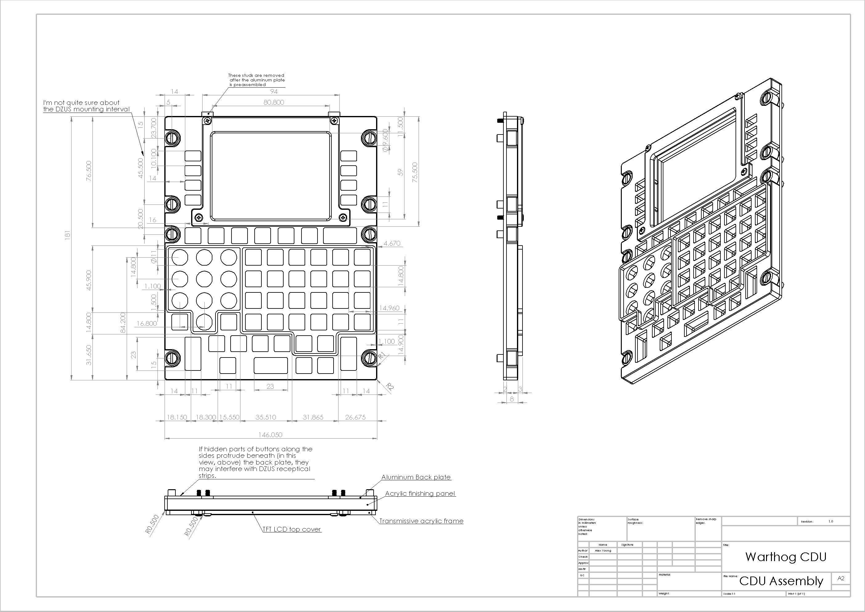
I just uploaded the blueprints of my CDU panels and buttons and added some details on the building process. The link to the blueprints can be found at the bottom of the first post of this thread.
-
Coole Sache. Wird es einen Mitschnitt (Podcast oder so) von dem Vortrag geben?
-
RC Scale Warthog A-10 Remote Control Turbine Jet
Waxi replied to EFDAZZYD's topic in Screenshots and Videos
I didn't know they also simulate EFATO procedures with model planes :music_whistling: What would be cool is a paint ball marker gun in one of these models... -
Latency will probably also be no issue when using a switch matrix, which seems to be more efficient than my approach where latency is already unnoticeable (what was the intended message of my previous post). I agree that there are probably more efficient ways to wire up digital/analog inputs/outputs and I appreciate learning about them. However, since this were my first steps in building electronics, I was looking for a simple starting point, in particular with regard to debugging. More sophisticated solutions will come as I advance my electronics skills :book: The Arduino Mega is not only planned to be used for running the digital inputs of the CDU and AAP. As I continue building my pit, I will hook more components to it and extend its firmware accordingly. Furthermore, when EOS and its integration into HELIOS is stable I can easily make my Arduino talk to HELIOS directly. Its firmware already uses a very similar protocol that can be easily replaced with the EOS protocol stack.
-
I use an Arduino Mega 2560 and 5 high speed multiplexers to multiplex the 80 digital inputs of the CDU and the AAP switches down to 5 inputs pins of the Arduino. There is no noticeable delay and I even make my Arduino wait for 10ms after each iteration over all inputs.
-
I checked "ejection handles" in the poll but I would also be interested in a seat pan and a fire control safety lever.
-
Thanks for the positive feedback :v: @TomDK: My screen (data sheet) has a VGA connector, which made connecting the display to the graphics card easy. After some initial problems selecting the right resolution on Windows 8 the display now works like a charm. It is recognized by Windows as a regular screen with a resolution of 640x480 and integrates into the overall Windows display area without problems. For exporting the CDU screen from DCS I use the Easy Monitor Configurator by icemaker, which saves quite some editing of Lua files. Soldering the 67 push buttons, 42 LEDs and particularly all the wiring for the electronics indeed was an annoying experience :bored:
-
After months of reading I finally decided to try whether I can keep pace with the excellent builds and replicas presented in this and other forums. My goal was building replica panels without buying expensive tools such as a laser cutter/engraver or a CNC mill. I started with the most annoying panel: The control display unit (CDU) with its 67 push buttons. My CDU is not an exact replica but close and I am very happy with the result of this first attempt: More pictures (also from the building phase) can be found in my photo album. The buttons and panels are made from clear acrylic. I ordered them from a German company that laser cut all parts very precisely according to my plans drawn in Adobe Illustrator (see below). It took about one week from placing the order and the delivery. The overall costs for all acrylic parts (including material, cutting and delivery) was about 60 Euros. Much cheaper than I expected! The display used is a 3.5" open frame TFT that is connected to my graphics card using a DVI to VGA adapter. I ordered it from another German company that has a great variety of such small displays at reasonable prices. For the electronics I use five high-speed MUXes to multiplex 80 digital inputs (the electronics is ready to take the digital inputs from the auxiliary avionics panel as well) to only 9 pins on an Arduino Mega 2560. These MUXes support multiplexing and de-multiplexing of digital and analog signals, which should allow me to drive the entire right console with one single Arduino Mega 2560. The electronics talks to a self-written software that translates between the Arduino and the a slightly modified version of Gadrocs' DCS Export.lua (the one that comes with HELIOS). I also have an Arduino firmware based on EOS that directly works with HELIOS but due to the early development stage of EOS I decided to cook my own soup for now. The button labels are made from clear self-adhesive transparency printed with a color laser printer. Specifically, each button label consists of: A layer of standard white printing paper with a mirrored black print of the button label on the bottom side (to block the light from the LEDs) that is glued to the button top using all-purpose adhesive; A layer of self-adhesive clear transparency printed with the gray button label; A layer of clear self-adhesive transparency to protect the printed labels. The CDU panel is colored in a similar fashion, i.e., it is not painted. I used the same transparencies and printed the black-and-white pattern of the CDU panel to them using the laser printer. Specifically, I printed the same pattern to the same transparency about four times until the black areas were completely opaque. The edges of the panel are painted using a black Edding 750 paint marker. I may post more details on the building process later. EDIT: I just uploaded the blueprints of my CPU panels and buttons that I used for the laser cutter. The file can be opened with Adobe Illustrator. The blue lines are cut lines and the red lines are engravings. My plans are based on the plans by Alex Young. The display frame is made from 3 mm black opaque Plexiglas GS with mat surface. The light, front and base plates are made from 3 mm clear Plexiglas GS. The middle part of the buttons is made from 8 mm clear Plexiglas GS. If I would build it again, I would use 3 mm milky white Plexiglas GS for the face plate and the top layer of the buttons, which nicely diffuses the light of the LEDs. I made the buttons from the cutouts of the button holes in the panels and the 8 mm middle pieces. I glued them together with general purpose adhesive based on cyanacrylate. It is very important to be very exact here and to use the right amount of glue. Slight inaccuracies can be evened out using sandpaper. There are some more photos of the building process that should give you an idea of how the buttons look like. The buttons are held in place as follows: Each button has a base layer that is wider than the holes in the top layers of the panels. This prevents the buttons from falling out of the upper side of the panel. From the backside the push buttons are supporting the buttons preventing them from falling out of the bottom part of the panel. EDIT 2: Please note that my blueprints contain all parts of the CDU panel and buttons in one single file. If you order the parts at some company, you probably have to make a single file for each part (base plate, light plate, face plate, etc.) from my plans. EDIT 3: Instead of using 5 multiplexers you could also use less multiplexers in a switch matrix. However, in contrast to my approach, a switch matrix may generate false inputs when pressing multiple buttons at the same time (known as "ghosting"). Further, a switch matrix may be harder to debug in case something goes wrong with the soldering. CDU Blueprints.zip
-
There is the TMWH Hardware Manual with a detailed view of the throttle base on page 9. However it has no measurements.