Hansolo
-
Posts
1775 -
Joined
-
Last visited
-
Days Won
1


-
Hello gents, Some of you may know, last year we lost a fellow dedicated pitbuilder MacFevre a.k.a. Wayne. Equally dedicated pitbuilder Warhog wrote this; Now his wife Kristine is selling he pit parts which can be found here on Ebay; https://www.ebay.com/sch/krislef82/m.html_nkw=&_armrs=1&_ipg=&_from= If you see anything you like please make a bid and assist her in move back to Illinois. Thanks Solo
-
Agreed. The dial moved same direction as the knob. The knob has a small pit IIRCC which forces the dial to move Cheers Solo

-
Jesus this is sad news, John. Thanks for letting us know. I worked in parallel with Wayne back when both of us where build a prototype of Deadmans cockpit plans. A very open and helpfull gentleman. Rest in peace Wayne
-
Hi Markus, If you have a rotary switch with 20 positions each with their individual pins you can use this const byte uhfPresetSelPins[21] = {PIN_0, PIN_1, PIN_2, PIN_3, PIN_4, PIN_5, PIN_6, PIN_7, PIN_8, PIN_9, PIN_10, PIN_11, PIN_12, PIN_13, PIN_14, PIN_15, PIN_16, PIN_17, PIN_18, PIN_19, PIN_20}; DcsBios::SwitchMultiPos uhfPresetSel("UHF_PRESET_SEL", uhfPresetSelPins, 21); If you turn the switch from position 3 to position 4 then on SOCAT you should be able to see UHF_PRESET_SEL 4 If you turn it further to position 5 SOCAT should show you following; UHF_PRESET_SEL 5 Note that this is being send a plain text Similar to this example Now in the AN/ARC-164 example I didn't have a 20 position switch with individual pins for each position. Therefore by using sendDcsBiosMessage I can send the same plain text over SOCAT. In my example I am looking at pin 29-22 for the combination from the preset selector. If pins 29-22 read the following B11111001, the the position is preset 3. If DCS is at another preset then using sendDcsBiosMessage the message to DCS to set preset no 3 with this code; if ( Preset() == 3){ sendDcsBiosMessage("UHF_PRESET_SEL", "3"); On SOCAT you will see; UHF_PRESET_SEL 3 which tells DCS to set preset no 3. Hope this explains it a little bit. Cheers Hans
-
Hi Markus, I haven't looked at it but you could do something similar as I did for the AN/ARC-164; Under presets I derive the position based greycode (IIRCC). Cheers Hans
-
Beautiful build Sir. Very nice looking
-
Hi Markus, I am quite certain this is the one; https://www.dropbox.com/s/izmxojksfrm4ros/Timer-master.rar?dl=0 Cheers Hans
-
Awesome work as always Anton
-
Awesome job Anton. Looks very good indeed sir. Very frustrating the force sensing couldn't work though. Cheers Hans
-
The Anti-collision light switch, anti-skid and the 4x SAS switches are magnetic held toogle switches. When applying voltage (originally 28VDC but 12VDC also works) the bat will stay in ON position once manually activated. You can force it back into OFF position by toggling in the other direction. If you remove voltage to the coil they will automatically flip back into OFF position. Here is a few older YT I did with them Cheers Solo
-
Jesus you have come a long way Anton. Awesome looking MFCD's sir. Best ones I have seen And the CMSC is very good. Looking forward to seeing more. Cheers Hans
-
Awesome work sir
-
Mr.Burns, try and look at this; https://easyeda.com/qrethus/arduino-nano-and-max487-chip-with-female-rj45-connector I don't know who did it but there is a good chance he is here on the forum. Alternatively talk to Tekkx. He might still be doing his breakout boards; In his signature there is a link for his hardware solution. If you want to DIY then I suggest using the prototype PCB I used in the opening post; https://www.ebay.com/itm/Prototype-PCB-8-5-x-20cm-Universal-Matrix-Printed-Circuit-Board-Arduino-AVR/402615276324?_trkparms=aid%3D111001%26algo%3DREC.SEED%26ao%3D1%26asc%3D20160908105057%26meid%3D3e96f2c703cc4326b9c3c8210869fd83%26pid%3D100675%26rk%3D2%26rkt%3D15%26mehot%3Dnone%26sd%3D124513653639%26itm%3D402615276324%26pmt%3D1%26noa%3D1%26pg%3D2380057&_trksid=p2380057.c100675.m4236&_trkparms=pageci%3A108f0def-9a25-11eb-9356-a6bbe5552638|parentrq%3Abce6f0351780a7b21ce9e076fff7f5ce|iid%3A1 That way you don't have to solder directly on the pins for the MAX487 socket. cheers Solo
-
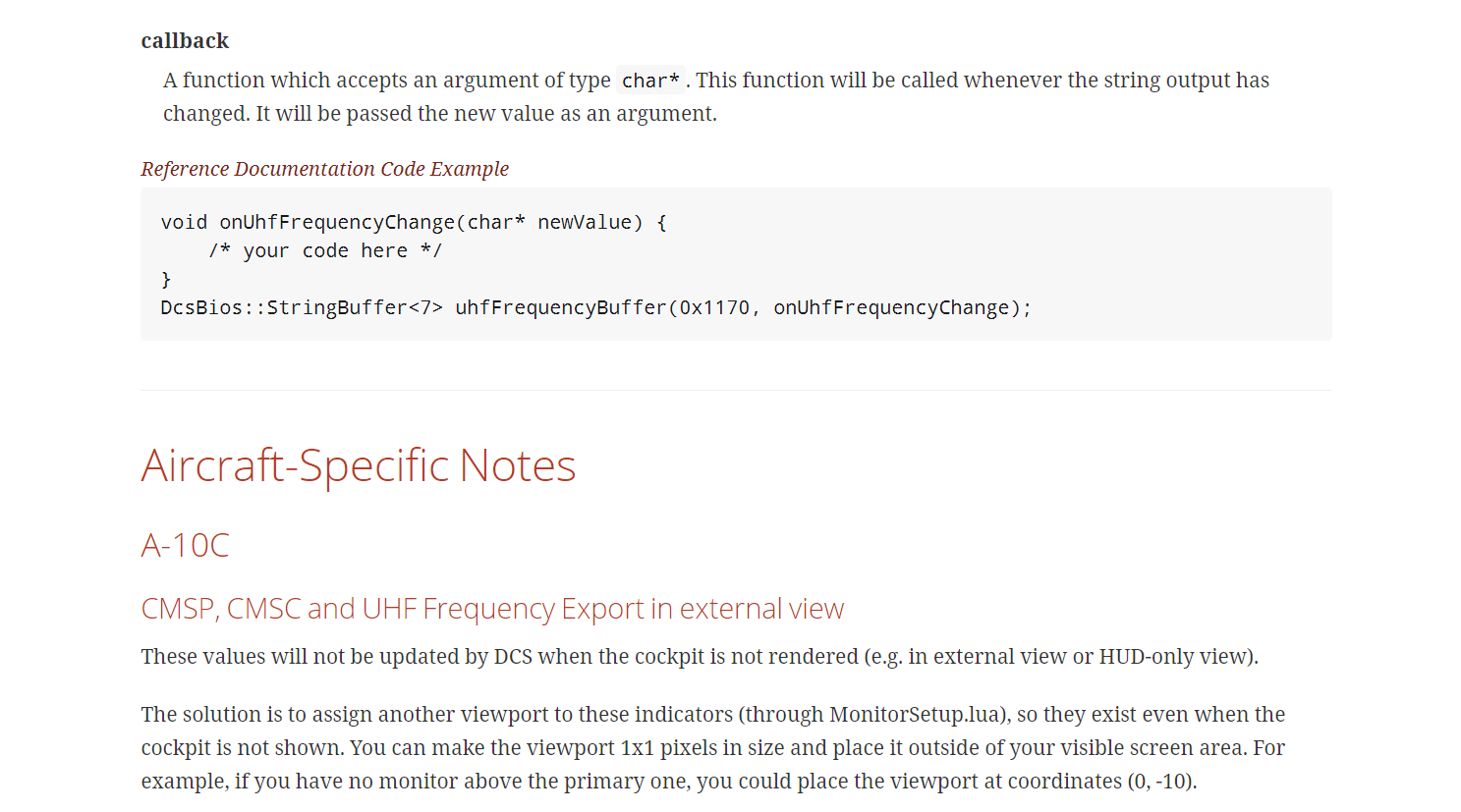
Not sure what module you are running but for the A-10C you need to have a viewport for the CMSP, CMSC and UHF. E.g. you need to export it to you monitor first, it doesn't have to be large and IIRCC it doesn't have to be visible e.g. you can export it outside your visible screen area. Below screen dump is from the original manual. Granted may have changed. Cheers Solo
-
The way I have seen on-on-on is by wiring a 2-pole 3 position switch like this; https://sensing.honeywell.com/2TL1-12-toggle-switches In this way: Cheers Hans
.jpg.f0e16001e786493632708083e18e6b12.jpg)