Kodoss
-
Posts
71 -
Joined
-
Last visited
Content Type
Profiles
Forums
Events
Everything posted by Kodoss
-
Drawing of main frame, one piece instrument carrier out of 5-10mm metall (al? ), A-frame screwed and riveted. Drawing of spare frame, instrument carrier out of riveted metall plates, A-frame glued and riveted Shows the riveting of the the -41 A-frame. Both A-frames are out of 2mm metall as you can see in cut C-D. Have fun.

-
I looked into the drawings of the canopy frames 8-190.166-33 and 8-190.166-41 which were used for the Fw 190 A-8 and D-9. Both have no wood at this area, only a 2mm thick metall frame.
-
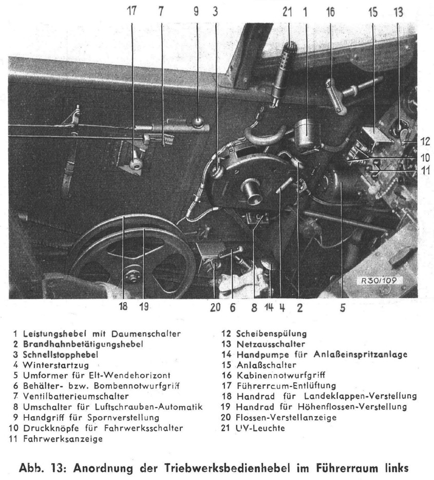
I can't tell for the D-9, since I don't have the handbook Part 8B for it. But if it's the same as in the A-5/A-6, then activate the V 50 fuse + an energy source(battery/running generator) and the lights go on. From the A-8 drawing 8-190.9075-Z02 the V 50 fuse is first fuse of the right hand panel (closest to the instrument panel). By the way this drawing also says red "Off"-switches for V50, P1, P2, V5, E61, E10, E16, E12, A4, V350, L10, E33 and T1 pulled off.
-
I think it's a translation error in the english version. I have a copy of the german manual for the A-5/A-6 which states: "Das Anzeigegerät R 6 ist mittels zweier Linsenschrauben am Gerätebrett für Abwurfwaffe befestigt. Für eine 250-kg-, 500-kg- oder 1000-kg-Bombe am ETC 501 ist nur das rechte Schauzeichen über dem Zündschaltkasten belegt. Beim Beladen des Einhangrostes (4 ETC 50/XIII) sollen die drei anderen Schauzeichen genau wie das rechte beim Beladen des ETC 501 ansprechen. Nach Auslösen einer Bombe erlischt jeweils das zugehörige Schauzeichen." Translation of the last 3 sentences: "For a 250-kg-, 500-kg- or 1000-kg-bomb at the ETC 501 only the right indicator light above the ZSK is used. At loading the ER-4 (4 ETC 50/XIII) the other 3 indicator lights shall respond. After releasing of a bomb, the respectively corresponding light goes off." Also under III/ 2. Elektrische Anlage at the points c) and d) it states that the corresponding indicator lights has to be on by loaded bomb/s and activated electrical system (battery / generator power) + fuse(right hand panel V 50) but deactivated ZSK.
-
Since I couldn't find the handbook part 9B for checking the electrical power source, I made a way around that problem. Looking into the Jumo 213 Engine manual, it can be fitted with 2 generators with 3000W. Rotation ratio is 2x the engine RPM with max. 10 PS (hp). In the Bf 109 K-4 and the Fw 190 A-5/A-6 Is the Bosch generator FL 34218-1 fitted. Output: 2000W 29V +/-0,5V DC at 4000-6000 RPM (generator RPM) By looking into the Ta 152 H-0 handbook part 9B we have: Engine: Jumo 213 E Generator: 2000W 29V +/-0,5V DC Battery: 20Ah 24V With this we can also assume a 2000W generator for the Fw 190 D-9. Electrical loads (from the Ta 152 H-0 handbook): Constant loads: position lights, lights: 95W Pitot heating, heating clothes: 190W canopy glass heating: 410W observation (instruments): 15W fuel pumps: 300W radio: 530W compass-system: 15W art. horizon: 45W meassuring system: 20W = 1620W constant load short loads: engine starter: 350W elevator trim: 220W MW-system: 35W Signal-Device: 100W aiming and photo device: 100W MG 151 arming: 1600W(only for 2,7sec at arming) and shooting: 300W MK 108(engine) 100W = 1205W Conclusion: Keep the engine above 2000 RPM for loading the battery.
-
Under /mods/aircrafts/FW-190D9/Cockpit/Scripts/Gunsight_EZ42/device looking into the EZ42_param.lua told me: Dmin = 10 << should be 80 Dmax = 1000 Dmin2 = 250 Lmin = 10 Lmax = 40 :music_whistling: Another bug is the Reticle vanishing behind the "bar" by moving your head closer to the Revi. Also the 1% open cross in the middle of the Revi never changes by increasing/decreasing distance or wingspan.
-
Text says 1000m, but finger went one time to often down at tipping. Sorry.
-
As I'm reading through my book "He 162 Volksjäger - Letzter Versuch der Luftwaffe" i found this 3 sentences at page 371 about the EZ 42: "Das EZ 42 wurde im Herbst 1944 von der Firma Askania in Berlin fertig konstruiert.(206) Es war für den Zielbereich von 80-1000m geeignet und wog 13,6 kg. Vorgesehen für die Heinkel He 162 war der Einbau ab Mai 1945.(207)" 206 - Unterlüss Report 295/VI, Page 8 207 - Protocoll KdE from 12.2.1945 Pt. 12 "The EZ 42 was final constructed in autumn of 1944 by the company Askania in Berlin.(206) It was applicable for a target range of 80-1000m and weighted 13,6 kg. For the Heinkel He 162 the Installation was scheduled starting May 1945.(207)" Ingame we have a range from 10m to 1000m.
-
ISA = International Standart Atmosphere (0m, 15°C, 1013mPa)
-
The picture shows a AB 250-2 with 224 SD 1 bombs (215 kg weight) The fuses for this one are 79A and 69D. Other AB250 loads are: AB 250-1: measurements: 1632 x 381 mm 96x SD-2 (242 kg) AB 250-2: measurements: 1618 x 373 mm 224x SD-1 (215 kg) 144x SD-2 (280 kg) 40x SD-4 HL (210 kg) 17x SD-10 A (220 kg) 28x SD-10 C (274 kg) 34x Bodenmarkierungskoerper Mark 3 B AB 250-3: 38x Seemarkierungskoerper Mark 2S 108x SD-2 Zt. (256 kg) AB 250 kz.: 41x Luftmarkierungskoerper Mark 2 L 18x Bodenmarkierungskoerper Mark 3 B
-
found the other threat: http://forums.eagle.ru/showthread.php?t=128295 by the way http://www.cockpitinstrumente.de has the crosshair sight of the EZ 42 in one of their pictures under "optisches System EZ?" http://www.deutscheluftwaffe.de/instrumente/katalog/revi/gross/EZLinsen4.gif
-
Bug/error: EZ 42/1-A1 The Revi is activated through the fuse-switch V24 (right hand panel) and not through the switch on the right sight of the Revi (below the distance indicator). The switch below the distance indicator is for activating the gyros of the Revi, so you can switch between arrested (switch in down position, important for bombing) and loose (switch in up position: gyros on, waiting time until full activation 1,5 min). The Revi sight also has a scale division in 1° units for bombing. Translated text of "D.(Luft)T.g.6413 - EZ 42/1-A1" page 5: EZ42/1 for bomb drop For the use in a fighter/bomber is the sight for prediction determination provided with a scale division. For bomb drop is the Revi-sight fixed and the target circle adjusted to biggest diameter (smallest distance). Also see Page 14 point 10): The sight can also , if necessary, be used as a fixed Revi. After shifting the switch into down position the automatic prediction control will be deactivated, the mirror returns to center position. Note thereby: to get a 10% circle, is the span distance knop to adjust at the catch 11,5 m, catch 16,5 m or catch 31,8 m and the distance set to 115 m resp. 16,5 m resp. 318m on the distance scale (colored markings at the distance scale).
-
Need assistance for understand the "Gun Ammunition Count"...
Kodoss replied to Skulleader's topic in DCS: Fw 190 D-9 Dora
If you look into the wire diagram of your manual (Anlage 3: Anlagenschaltplan für starre Schusswaffe) at the SZKK-4, you can see that the 2'nd switch (left to the main switch) isn't used. -
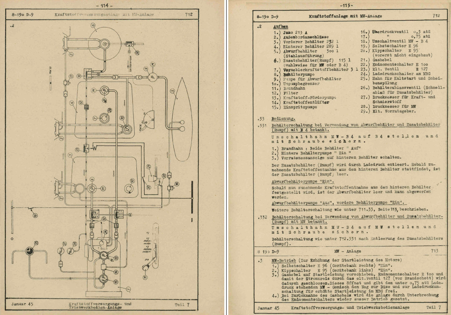
The oxygen tanks have no order. They were filled and emptied equally. Max filled pressure is 165 atü. One oxygen ball bottle (Fl30380-8 ) has a capacity of 2 litres. MW50-B4 selector is position 51 at panel IV (left panel near left wall, below the IV) [ATTACH]94864[/ATTACH] Fuel lines and electric lines for MW-50 use. The MW-50-B4 selector is secured through a screw, to prevent accidents.
-
Hangar 10 also restores a Fw 190 D-9: http://www.hangar10.de/de/news-section-de/63-fw-190-d9 They also have a Bf 109 G-14 and a P-51 D-20 NA.
-
@ tapi, If you take your picture of the cockpit and combine it with this picture of the main circuit plan, then you can guess it out yourself. But to decipher the correct text at the front fuse panel is insanity. from L.Dv.T. 2109 K-4/Fl Teil 2
-
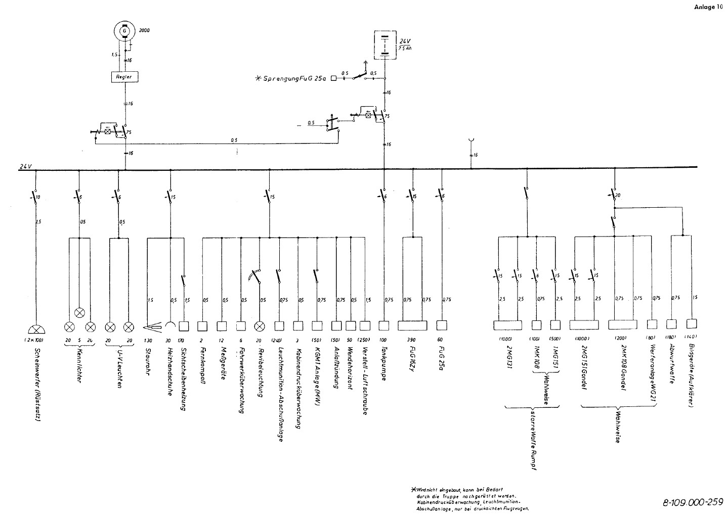
Circuit breaker panel X 15A - marks the 15 Ampere circuit breaker and the and the connected device + marks the also connected device to the circuit breaker above 170W - constant needed power (80W) - needed power Front circuit breaker line X 75A | Generator 24V 2000W X 15A | Staurohr (pitot heater) 130W + | Sichtscheibenheizung (window heating) 170W + | Heizhandschuhe (heated gloves) 30W X 5A | Kennlichter (position lights) 20W 5W 20W X 5A | UV Leuchten (UV lights) 20W 20W X 20A | Bildgeraete [Aufklaerer] (recon camera) (140W) + | Flügel Waffen (either Werferanlage WG 21 (80W) or wing MG: MG 151(/20) (1000W with an additional 15A circuit breaker per MG) or MK 108 (200W w/o additional circuit breaker)) + | Abwurfwaffe (bomb rack) (180W) X 15A | Fernkompass (compass) 2W + | Messgeraete (instruments) 12W + | Fahrwerkueberwachung (landing gear) 6W + | Revibeleuchtung (Revi light) 20W + | Leuchtmunition-Abschussanlage (signal ammunition device) (240W) + | Kabinendruckueberwachung (cabin pressure control) 3W + | KGM1 Anlage [MW] (MW injection device) (50W) + | Anlasszuendung (starter ignition) (50W) + | Wendehorizont (turn indicator) 50W + | Verstell-Luftschraube (adjustable propeller) (250W) [X 10A | Scheinwerfer [Ruestsatz] (landing lights (2x 100W) ) ] Rear circuit breaker line X 75A | Battery 24 V 7,5 Ah X 15A | FuG 16 390W X 5A | FuG 25a 60W X 5A | Tankpumpen (fuel pumps) 100W Switch at the SZKK3 controls: + 2x MG 131 (1000W); (each 500W, secured throu a 15A circuit breaker per MG) + 1x MK 108 (100W); (100W with 5A circuit breaker) or + 1x MG 151(/20) (500W); (500W with 15A circuit breaker) By the additional "Selbstschalter" at the MGs, those are circuit breaker switches, but those can't be accessed in flight.
-
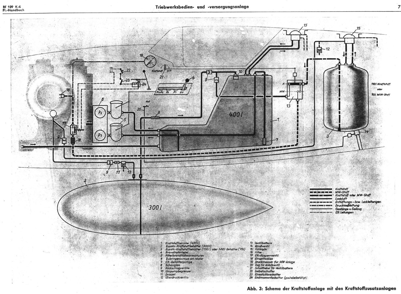
Fuel and circuit lines from the Bf 109 K-4 handbook: The dashed line is the MW 50 fuel line. 21 - mechanical switch for 13 - valve row (Ventilbatterie) 22 - circuit breaker 23 - Stand-by-switch (Einsatzklarschalter) at the intrument panel 24 - on-switch; activated through the throttle-lever
-
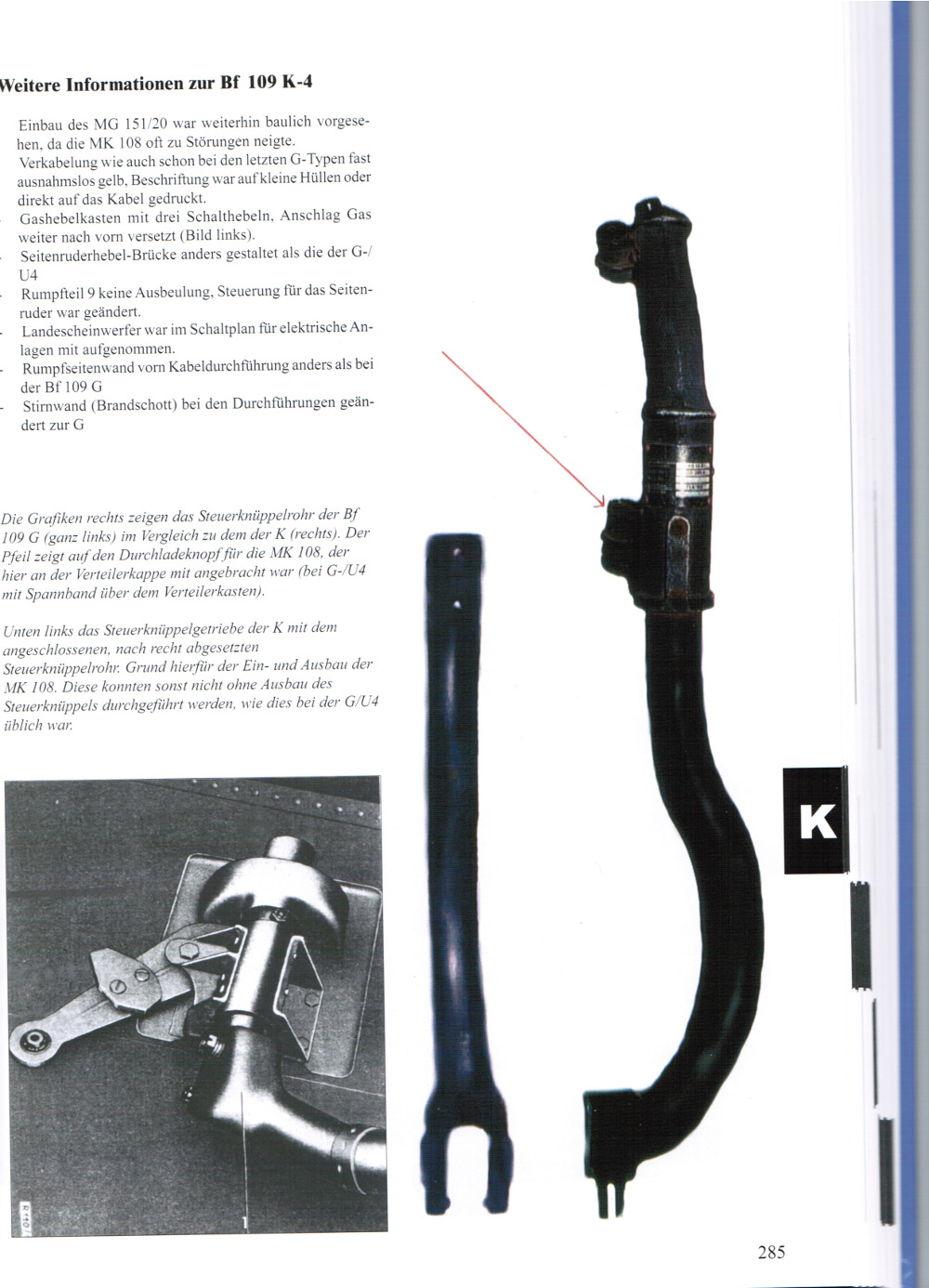
The control column has to be redone.:music_whistling: Instead of a straight column it must be bend like a mirrored question mark. This was done to have better access to the MK 108 for installation/deinstallation. From the Bf 109 K spare parts list: From the book: "Messerschmitt Bf 109 - Einsatzmaschinen"; Harald Helmut Vogt; VDM-Verlag; ISBN-13: 978-3-86619-068-9 Also the switch for the GM-tank is missing (left cockpit side, below the tail wheel arrest). But the rest looks awsome:thumbup:
-
It was more due production shortage of necessary parts than through field mods. Radiator shutoff valves were built in from the F-series (not the early F-1) to the K-series. The spare parts lists (F,G and K-series) and handbooks lists them.
-
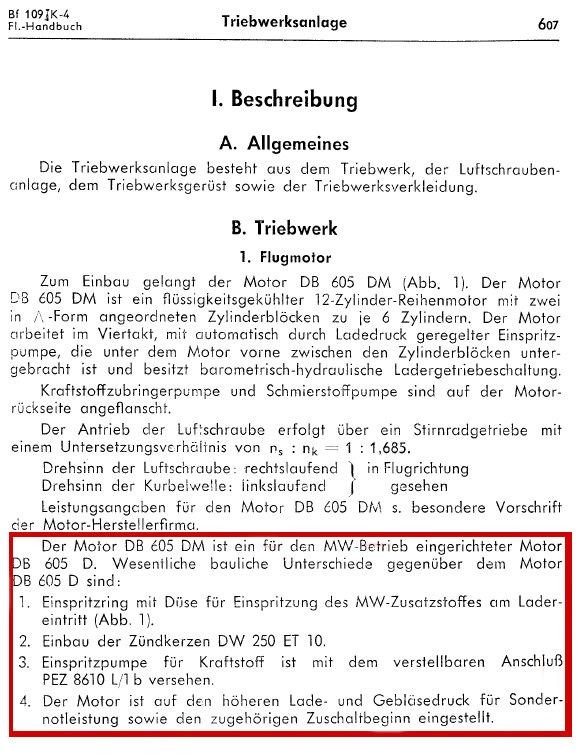
errr... DB 605 D-1 B4 fuel, no MW-50 injection DB 605 DM B4 fuel (no MW 50 usage allowed) or C3 fuel with MW-50 injection
-
Well the manual I quote speaks of a DB 605 DM engine. From what I've read also DB 605 D-1, DBM, DCM and also AS engines could be build in.
-
If MW 50 is used, then C3 fuel is permitted only. See "L.Dv.T.2109 K-4/Fl Teil 2" page 9 Which means "Sondernotleistung" = MW-50 injection is not permitted. But you can use the 115 L MW-50 tank as an additional fuel tank for B 4 or C 3 fuel. The lever to switch between MW-50/MW-30 and normal fuel mode is marked with #7. By the way, the lever #7 and the canopy handle to open the canopy is not modeled. But it's still WIP...:D
-
[REPORTED] Fw 190 Cockpit Bar! (answer Post #173)
Kodoss replied to Krupi's topic in DCS: Fw 190 D-9 Dora
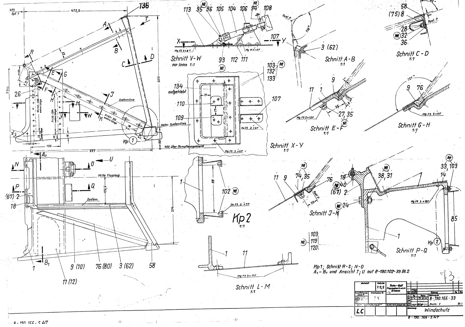
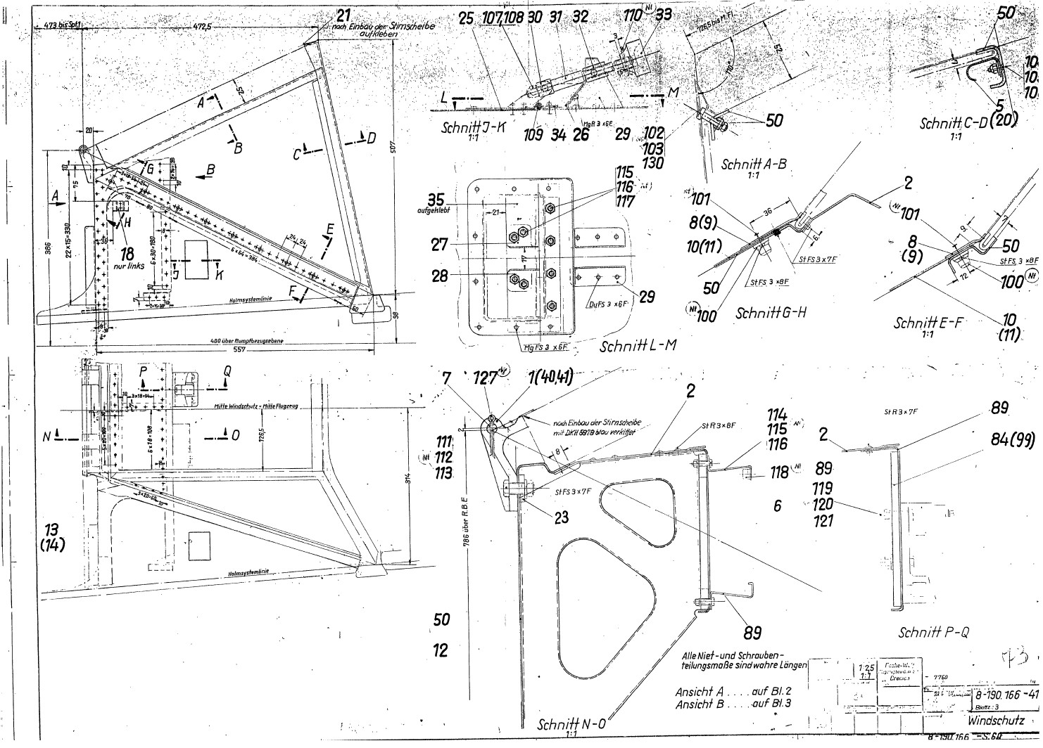
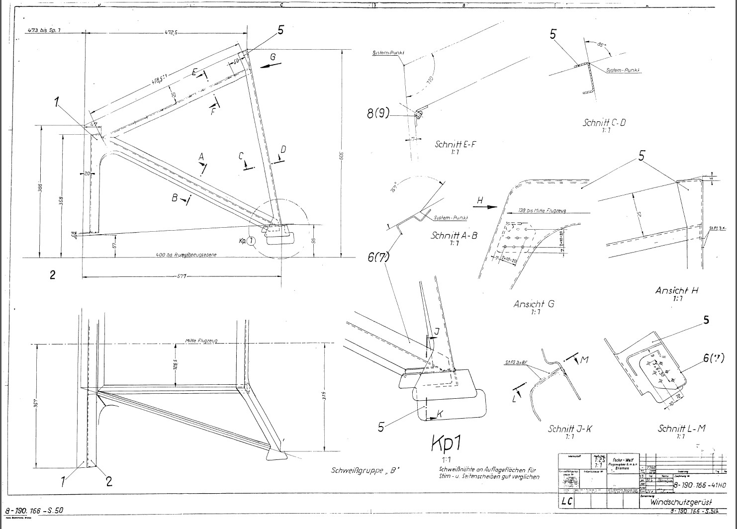
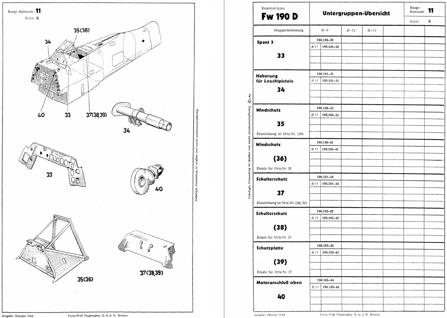
First pic is from the "original" FW 190 D-9 spare parts list (October 1944) Second pic is a production drawing from the Bremen factory for the A-8. Look at the drawing number and you will see, that the drawing of the frame has the same number >> same part by FW 190 A-8 and D-9. But that doesn't take into account the optical distortion of what you realy would see.:music_whistling: -
[REPORTED] Fw 190 Cockpit Bar! (answer Post #173)
Kodoss replied to Krupi's topic in DCS: Fw 190 D-9 Dora
From the FW 190 D-9 spare parts list: The technical drawing from the FW 190 A-8 Bremen production: Good invested money...:thumbup: