draken152
-
Posts
219 -
Joined
-
Last visited
Content Type
Profiles
Forums
Events
Everything posted by draken152
-
Based on my experience you shouldn't have a problem due this. I have several rotary switches where I am using one ground cable for 4-5 switches and I didn't have this problem...
-
Thx Hansolo. Guys can someone share with me Artificial Horizon construction and used parts. I have some knowledge how to do it but some inspiration from already working pit is realy welcome... I am missing just Artificial Horizon and compass and designing phase is done :) :helpsmilie:
-
Even I don’t understand why everyone wants A-10 pit :megalol: I must say your work is looking beautiful and really authentic :thumbup:
-
Thanks :pilotfly:
-
So here Some small findings: I think this should be also lamp class. (I have try it with my panel and was working Ok): defineFloat("GUN_FIRE_1", 50, {0.0, 1.0}, "Indicator", "Gun_Fire_1") defineFloat("GUN_FIRE_2", 164, {0.0, 1.0}, "Indicator", "Gun_Fire_2") defineFloat("GUN_FIRE_3", 165, {0.0, 1.0}, "Indicator", "Gun_Fire_3") defineFloat("GUN_FIRE_4", 166, {0.0, 1.0}, "Indicator", "Gun_Fire_4") Bomb lamps are twice in code as lamps and also as float: defineFloat("BOMB_LAMP_1", 196, {0.0, 1.0}, "Indicator", "Bomb_Lamp_1") defineFloat("BOMB_LAMP_2", 197, {0.0, 1.0}, "Indicator", "Bomb_Lamp_2") defineFloat("BOMB_LAMP_3", 198, {0.0, 1.0}, "Indicator", "Bomb_Lamp_3") defineFloat("BOMB_LAMP_4", 199, {0.0, 1.0}, "Indicator", "Bomb_Lamp_4") defineIndicatorLight("BMB1",196, "Lamps", "Bomb 1 Lamp") defineIndicatorLight("BMB2",197, "Lamps", "Bomb 2 Lamp") defineIndicatorLight("BMB3",198, "Lamps", "Bomb 3 Lamp") defineIndicatorLight("BMB4",199, "Lamps", "Bomb 4 Lamp") :music_whistling:
-
So pit floor assembled, also middle console tested and assembled to pit. Knipel base collar was made by one of my friends from leather....

-
Just contact Tekkx via PM. Or I can send you his email via PM if he will not respond. He usually have some boards in stock...
-
I have already 6 boards from Tekkx and he did a great job...Easy plug and play solution for RS485 pit network....:thumbup::thumbup::thumbup:
-
Working like charm man :thumbup::thumbup::thumbup: . Thanks a lot:worthy::worthy::worthy: I will make update the of the FW190D9.LUA for all of those issues and send it to Ian.
-
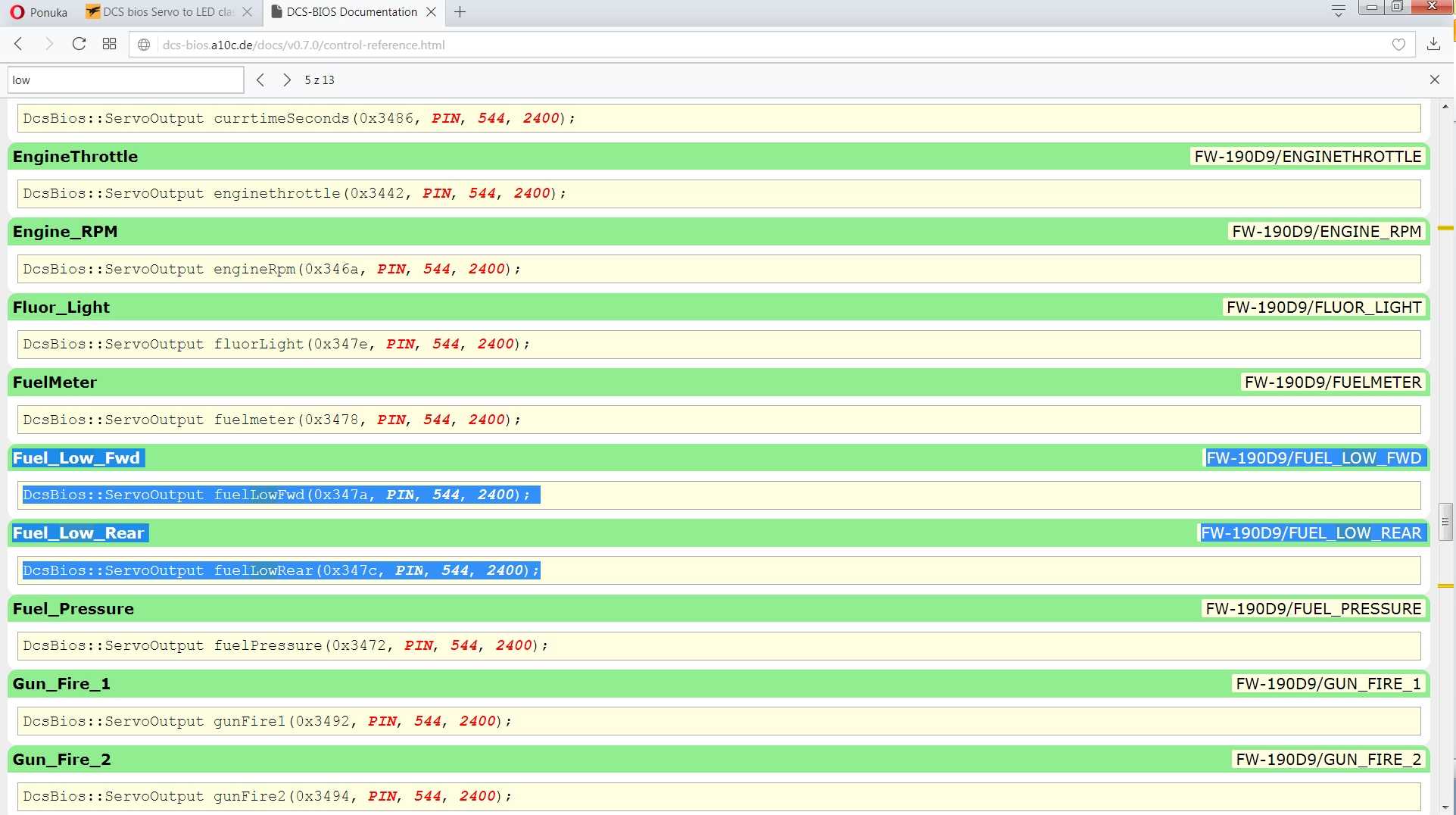
Hi ArturDCS, Thanks for respond. I have just user experience with DCS bios, I dont know if the code is autogenerated or is inputed by Ian, the code was simply copy from control reference (see attached picture). I thought you have made also class specification for each input/output (so also ServoOutput), then probably only Ian can help. What I only know from my opinion it should be LED output….
-
Ian, ArturDCS anyone????
-
Thanks. Corrected.
-
Having some problems and not enough time :( but still workig....
-
Hi guys, during my FW 190D panel building I have found one issue. Lamp for empty fuel tanks are in DCS bios coded as servos (and also some other lights): DcsBios::ServoOutput fuelLowFwd(0x347a, PIN, 544, 2400); DcsBios::ServoOutput fuelLowRear(0x347c, PIN, 544, 2400); I was trying to change it simple to LED class like this, (using mask from advance options) but it isn't working: DcsBios::LED fuelLowFwd(0x347a, 0xffff, PIN); It is possible to change it and how to do it correctly???
-

DCS Bios pointer calibration tool - gauge calibration
draken152 replied to draken152's topic in Home Cockpits
Ian thx for info. More or less I was just curious, live data of instruments arrow positions are enough for more precise calibration (again thx Patriot). Ian you have done amazing work with DCS bios only thx to you we can work on our dreams:thumbup::thumbup::thumbup: -
DCS Bios pointer calibration tool - gauge calibration
draken152 replied to draken152's topic in Home Cockpits
Thx extension is now running :thumbup: but when I click on the pointer calibration tool nothing happened
-
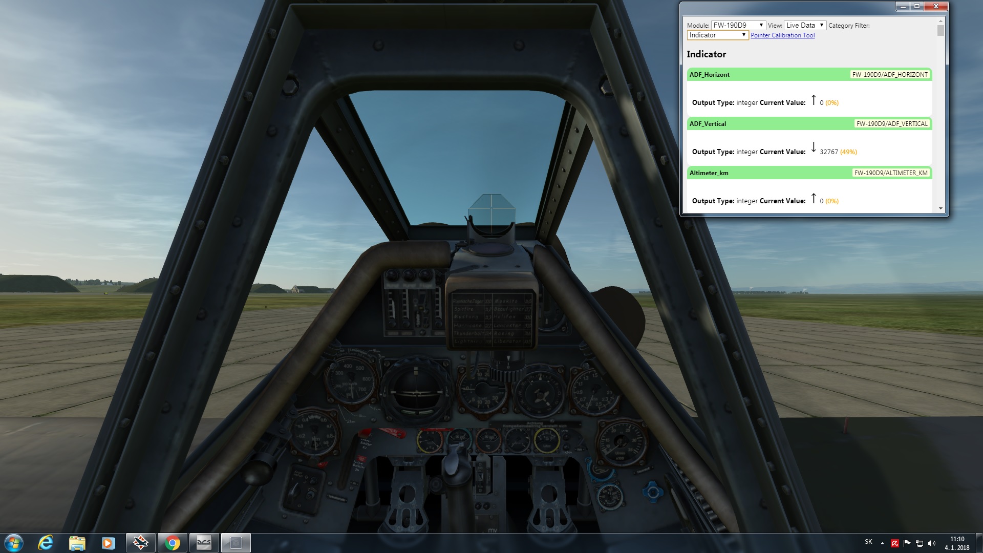
Hi guy, is anyone using DCS bios pointer calibratiom tool for gauge calibration. It is working??? Can somebody maybe post short guiide please:helpsmilie:. Currently I am doing all calibration manualy by visual comparation of DCS screen with gauge, and it is working, but I am sure there must be more scientific method. I am using vid 29s so one 1° shut be 12 steps but when I am trying to transform this to gauge movement I always fail with my calculation and reality (I dont know the incoming data from DCS) . What kind of procedures are you guys using for gauge calibration???
-
Thx to all. WhoMadeWho as I wrote in my guide it is well known Warhogs code for vid60. #define DCSBIOS_IRQ_SERIAL #include <AccelStepper.h> #include "DcsBios.h" struct StepperConfig { unsigned int maxSteps; unsigned int acceleration; unsigned int maxSpeed; }; class Vid60Stepper : public DcsBios::Int16Buffer { private: AccelStepper& stepper; StepperConfig& stepperConfig; inline bool zeroDetected() { return digitalRead(irDetectorPin) == 1; } unsigned int (*map_function)(unsigned int); unsigned char initState; long currentStepperPosition; long lastAccelStepperPosition; unsigned char irDetectorPin; long zeroOffset; bool movingForward; bool lastZeroDetectState; long normalizeStepperPosition(long pos) { if (pos < 0) return pos + stepperConfig.maxSteps; if (pos >= stepperConfig.maxSteps) return pos - stepperConfig.maxSteps; return pos; } void updateCurrentStepperPosition() { // adjust currentStepperPosition to include the distance our stepper motor // was moved since we last updated it long movementSinceLastUpdate = stepper.currentPosition() - lastAccelStepperPosition; currentStepperPosition = normalizeStepperPosition(currentStepperPosition + movementSinceLastUpdate); lastAccelStepperPosition = stepper.currentPosition(); } public: Vid60Stepper(unsigned int address, AccelStepper& stepper, StepperConfig& stepperConfig, unsigned char irDetectorPin, long zeroOffset, unsigned int (*map_function)(unsigned int)): Int16Buffer(address), stepper(stepper), stepperConfig(stepperConfig), irDetectorPin(irDetectorPin), zeroOffset(zeroOffset), map_function(map_function), initState(0), currentStepperPosition(0), lastAccelStepperPosition(0) { } virtual void loop() { if (initState == 0) { // not initialized yet pinMode(irDetectorPin, INPUT); stepper.setMaxSpeed(stepperConfig.maxSpeed); stepper.setSpeed(1000); initState = 1; } if (initState == 1) { // move off zero if already there so we always get movement on reset // (to verify that the stepper is working) if (zeroDetected()) { stepper.runSpeed(); } else { initState = 2; } } if (initState == 2) { // zeroing if (!zeroDetected()) { stepper.runSpeed(); } else { stepper.setAcceleration(stepperConfig.acceleration); stepper.runToNewPosition(stepper.currentPosition() + zeroOffset); // tell the AccelStepper library that we are at position zero stepper.setCurrentPosition(0); lastAccelStepperPosition = 0; // set stepper acceleration in steps per second per second // (default is zero) stepper.setAcceleration(stepperConfig.acceleration); lastZeroDetectState = true; initState = 3; } } if (initState == 3) { // running normally // recalibrate when passing through zero position bool currentZeroDetectState = zeroDetected(); if (!lastZeroDetectState && currentZeroDetectState && movingForward) { // we have moved from left to right into the 'zero detect window' // and are now at position 0 lastAccelStepperPosition = stepper.currentPosition(); currentStepperPosition = normalizeStepperPosition(zeroOffset); } else if (lastZeroDetectState && !currentZeroDetectState && !movingForward) { // we have moved from right to left out of the 'zero detect window' // and are now at position (maxSteps-1) lastAccelStepperPosition = stepper.currentPosition(); currentStepperPosition = normalizeStepperPosition(stepperConfig.maxSteps + zeroOffset); } lastZeroDetectState = currentZeroDetectState; if (hasUpdatedData()) { // convert data from DCS to a target position expressed as a number of steps long targetPosition = (long)map_function(getData()); updateCurrentStepperPosition(); long delta = targetPosition - currentStepperPosition; // if we would move more than 180 degree counterclockwise, move clockwise instead if (delta < -((long)(stepperConfig.maxSteps/2))) delta += stepperConfig.maxSteps; // if we would move more than 180 degree clockwise, move counterclockwise instead if (delta > (stepperConfig.maxSteps/2)) delta -= (long)stepperConfig.maxSteps; movingForward = (delta >= 0); // tell AccelStepper to move relative to the current position stepper.move(delta); } stepper.run(); } } }; /* modify below this line */ /* define stepper parameters multiple Vid60Stepper instances can share the same StepperConfig object */ struct StepperConfig stepperConfig = { 400, // maxSteps 2200, // maxSpeed 1000 // acceleration }; // define AccelStepper instance AccelStepper stepper(AccelStepper::DRIVER, 9, 8); // define Vid60Stepper class that uses the AccelStepper instance defined in the line above // v-- arbitrary name Vid60Stepper alt100ftPointer(0x107e, // address of stepper data stepper, // name of AccelStepper instance stepperConfig, // StepperConfig struct instance 11, // IR Detector Pin (must be HIGH in zero position) 0, // zero offset [](unsigned int newValue) -> unsigned int { /* this function needs to map newValue to the correct number of steps */ return map(newValue, 0, 65535, 0, stepperConfig.maxSteps-1); }); void setup() { DcsBios::setup(); pinMode(13, OUTPUT); } void loop() { PORTB |= (1<<5); PORTB &= ~(1<<5); DcsBios::loop();
-
place holder
-
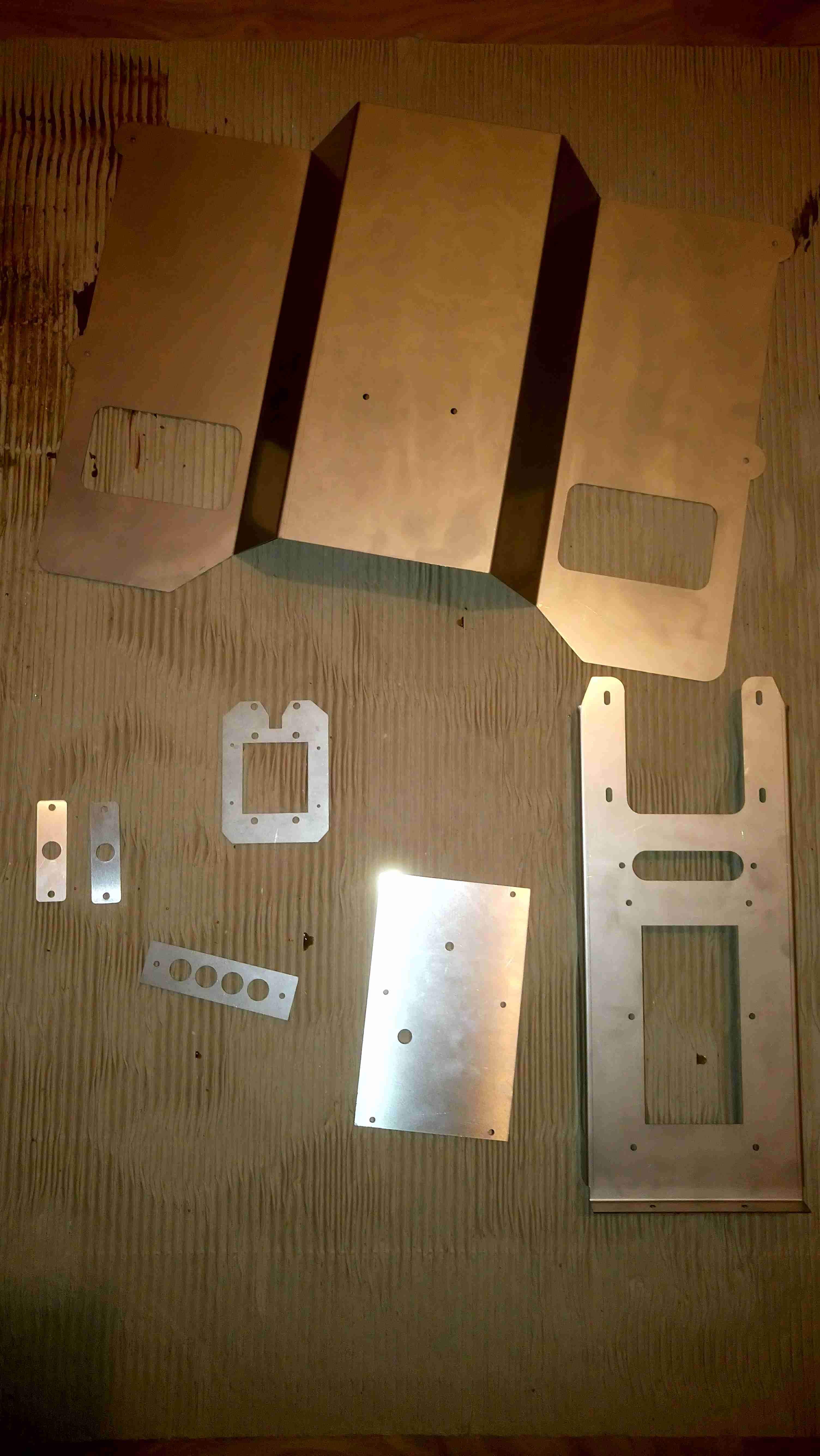
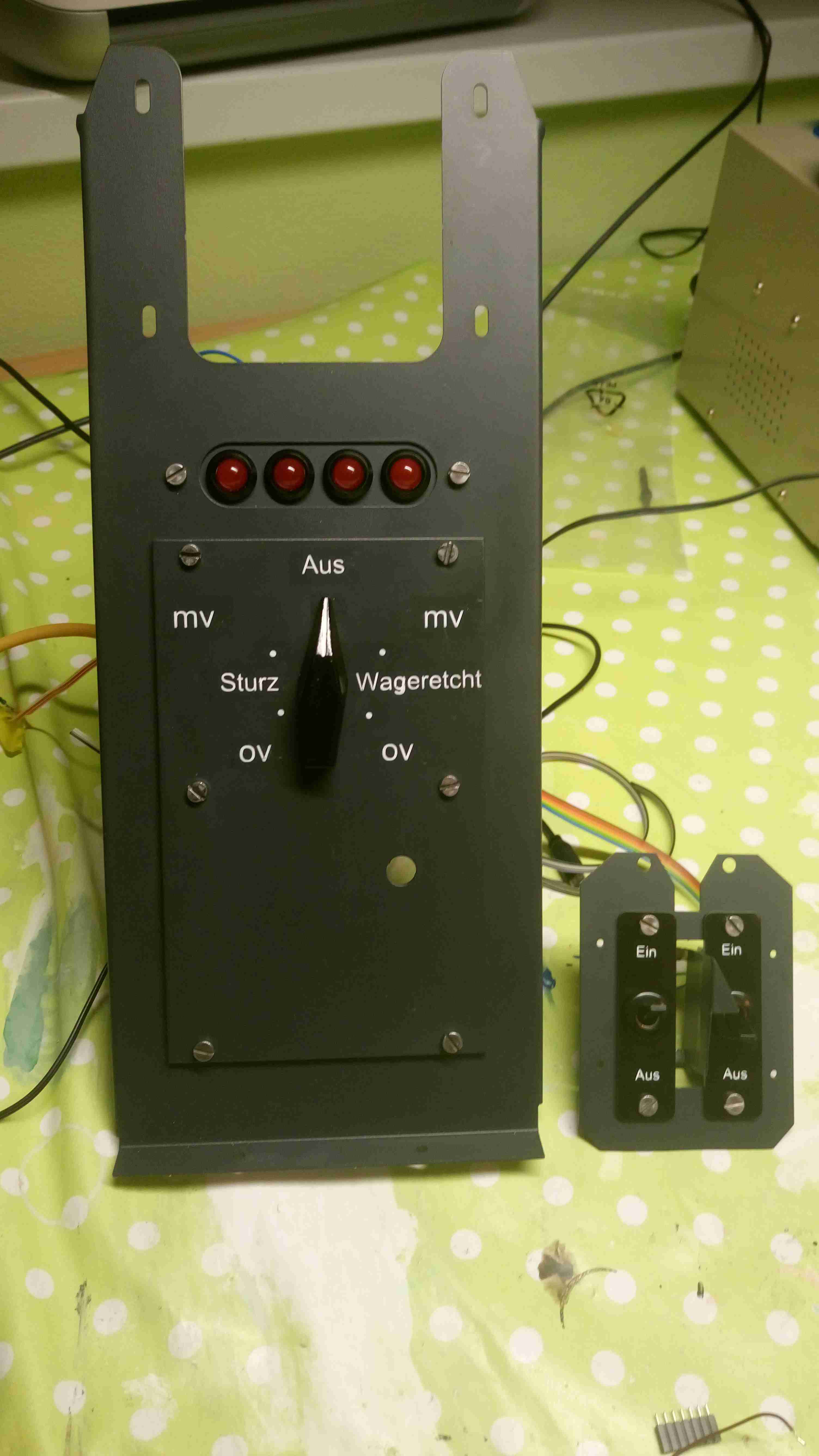
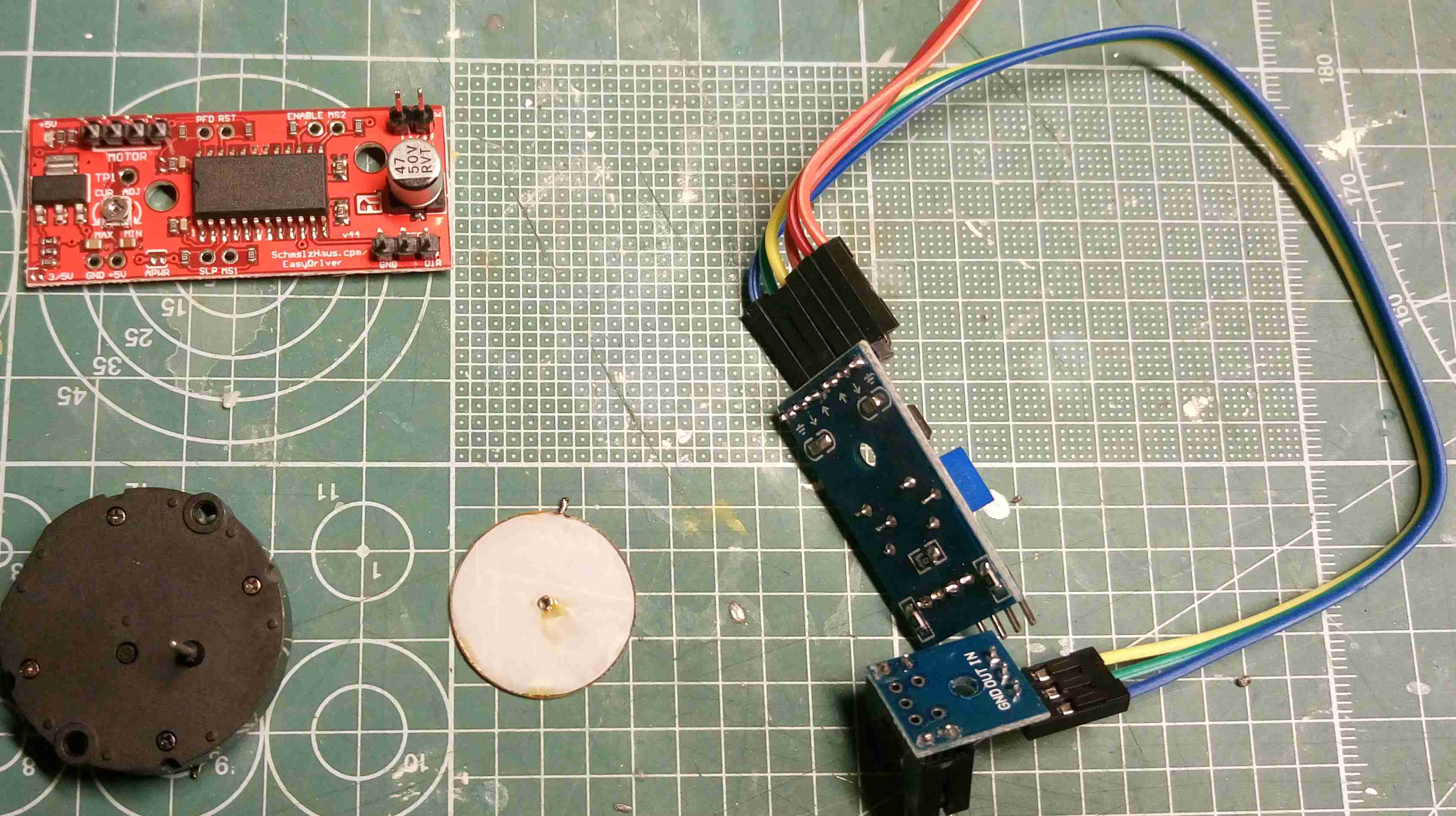
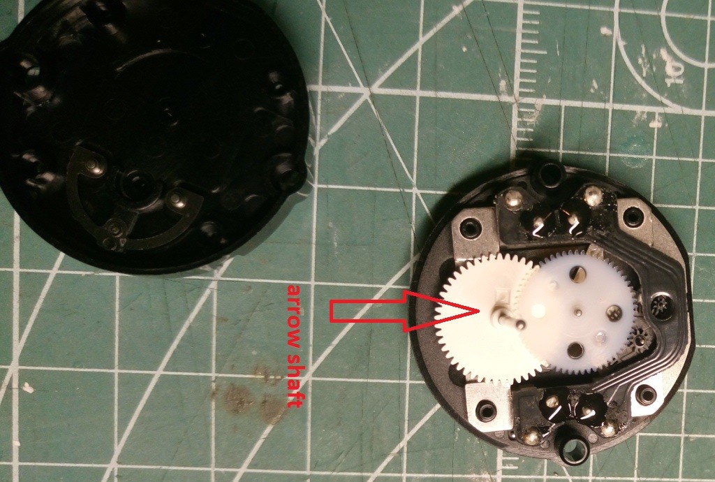
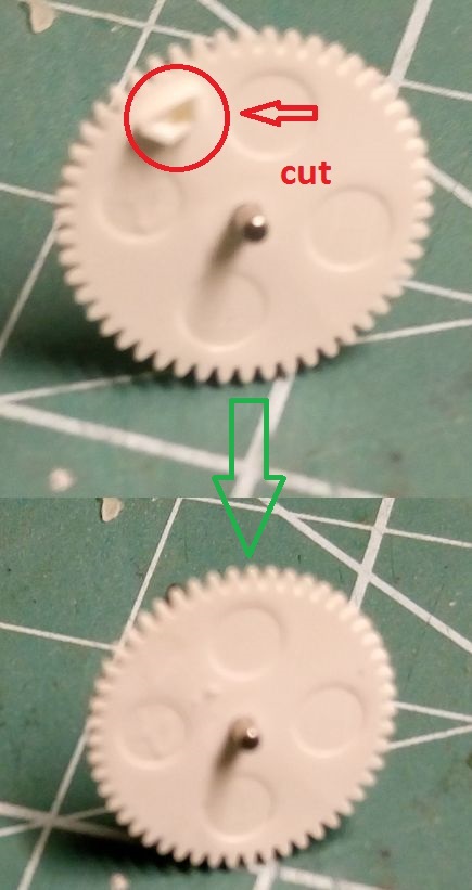
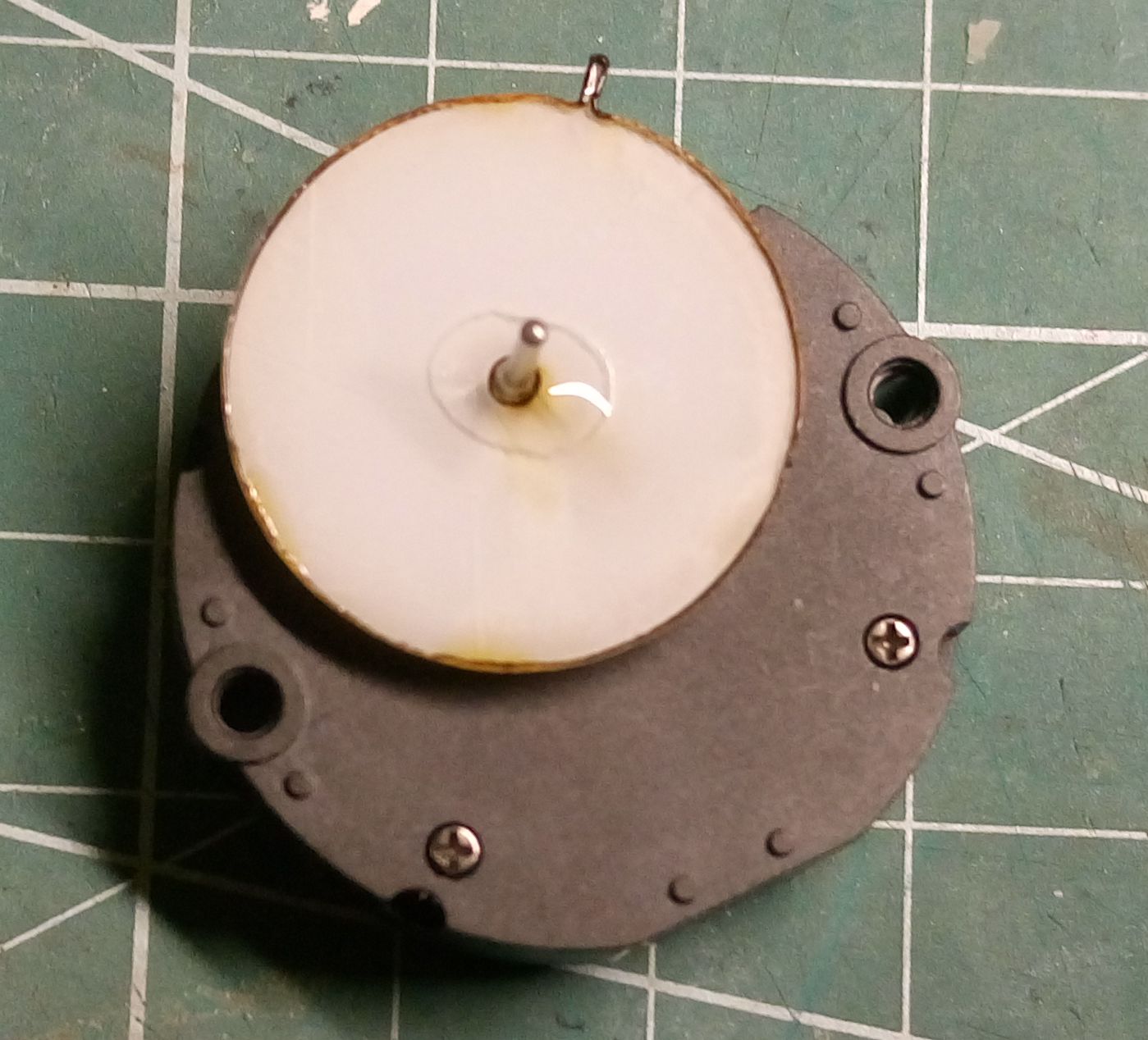
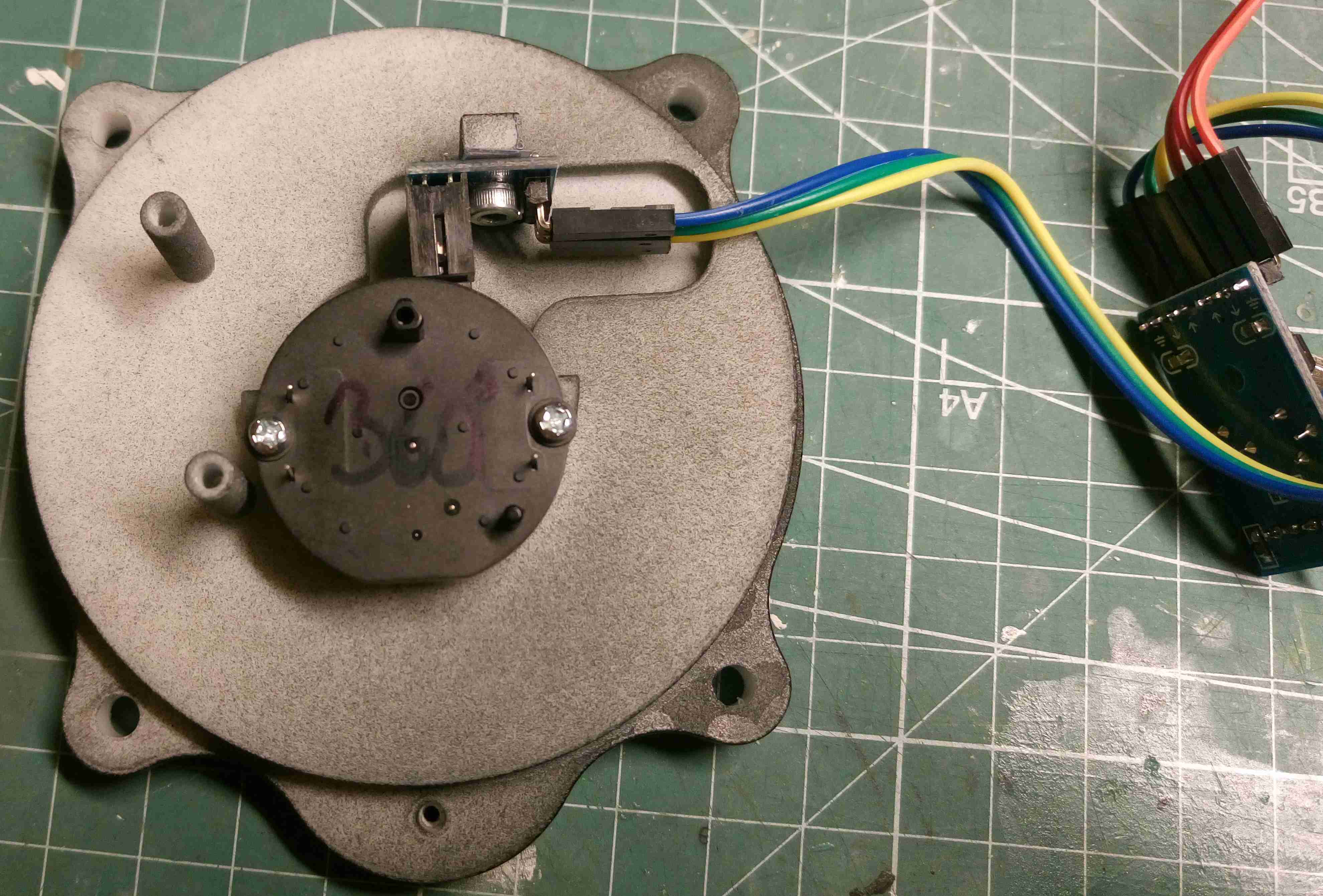
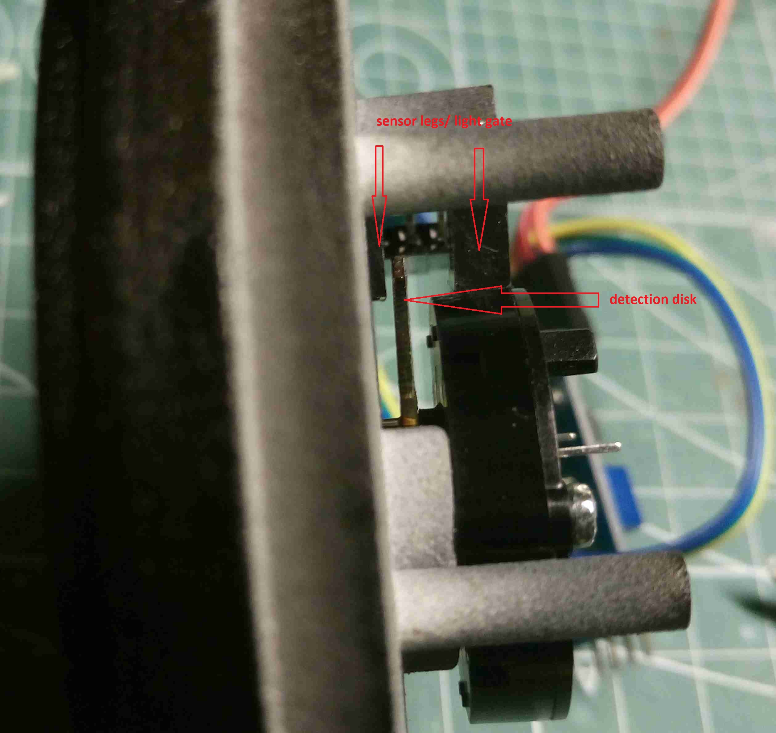
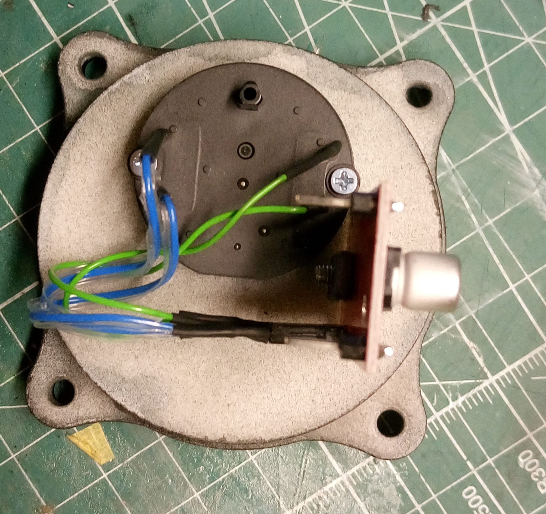
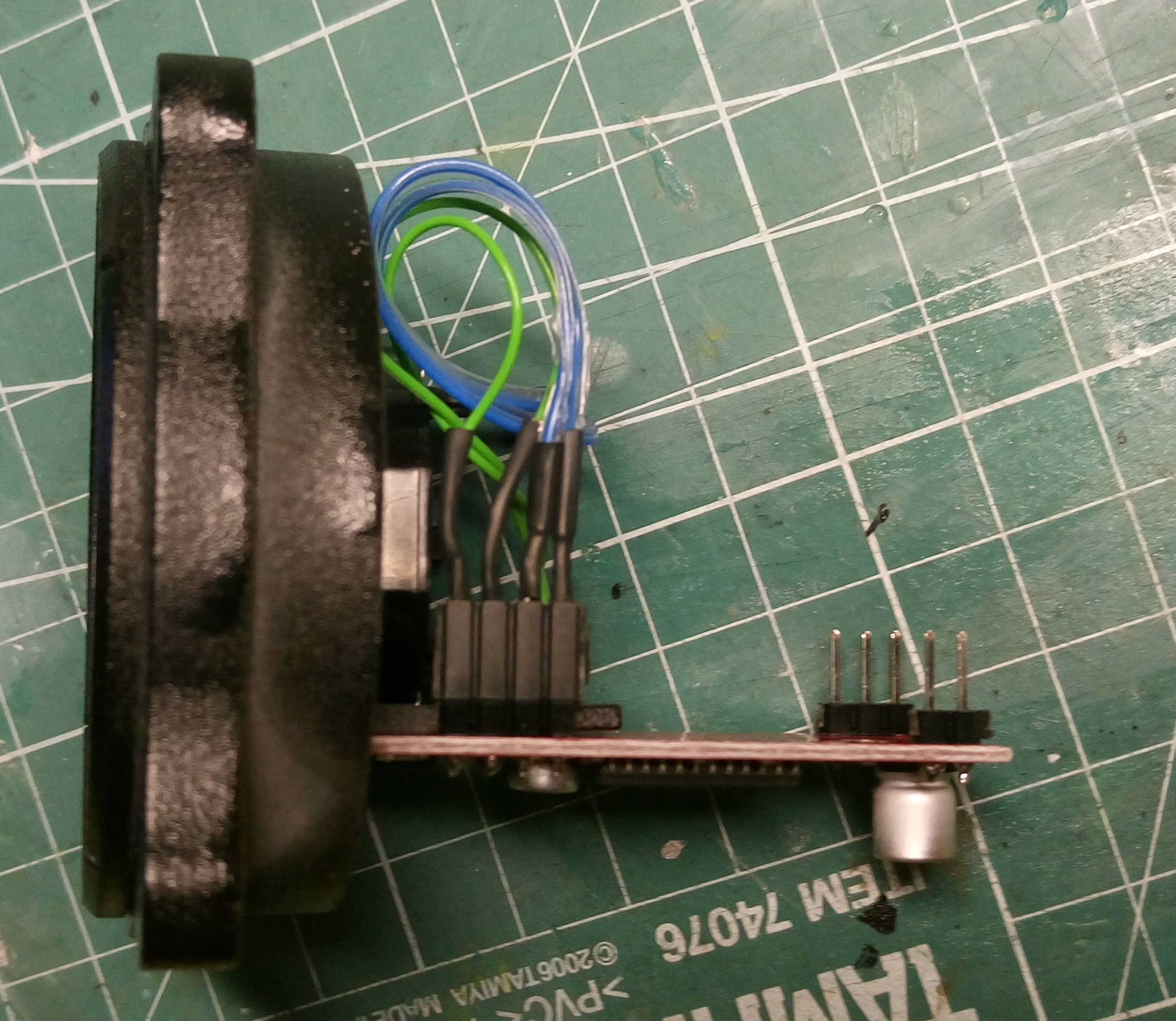
Hi Guys, Like some others also I have problems to obtain vid60 motors, than in one thread fbfan64 mentioned it is possible to mod vid29 to 360° movement. I made some investigation and pop up with this solution, for sure there are more solutions... So what we need (see pic1): Vid29 motor -link 2 Channel Speed Detection Sensor - link Detection disk - home made Easy driver (you don’t need it for mod but for testing) - link 1. Disassembly the 4 screw on vid 29 (pic2) and take out the arrow shaft with gear 2. From bottom side of the gear you can see a movement restriction pin. Cut it away with sharp knife (pic3). 3. Assembly vid29 back 4. Now you have motor with 360° movement but you need zero positioning. There are again more solutions but I prefer this because it is easy adjustable, precise and invisible from gauge front side. So glue on the shaft detection disc (pic4) 5. Now you just need to assembly your vid29 to gauge and assembly one of the sensors above it (pic5). Detection disk must be after assembly positioned between the two legs/light gate of sensor (pic6), and only the pin of the disk must be positioned in active part of sensor. So zero position is triggered by pin of the disk, sensitivity of sensor is easily adjustable by trimmer on the main pcb of sensors (when is pin detected the corresponding led on main board switch off) 6. Now just connect arduino, load Warhogs code....:music_whistling: P.S. Guys I think DCS pit building community is really missing more guides, more or less we have lot of threads with same questions because there are no guides... There are lot of skilled guys here on forum so let’s try to change this in next year... As idea for guides artificial horizon construction, gauge calibration procedure using dcs bios....
-
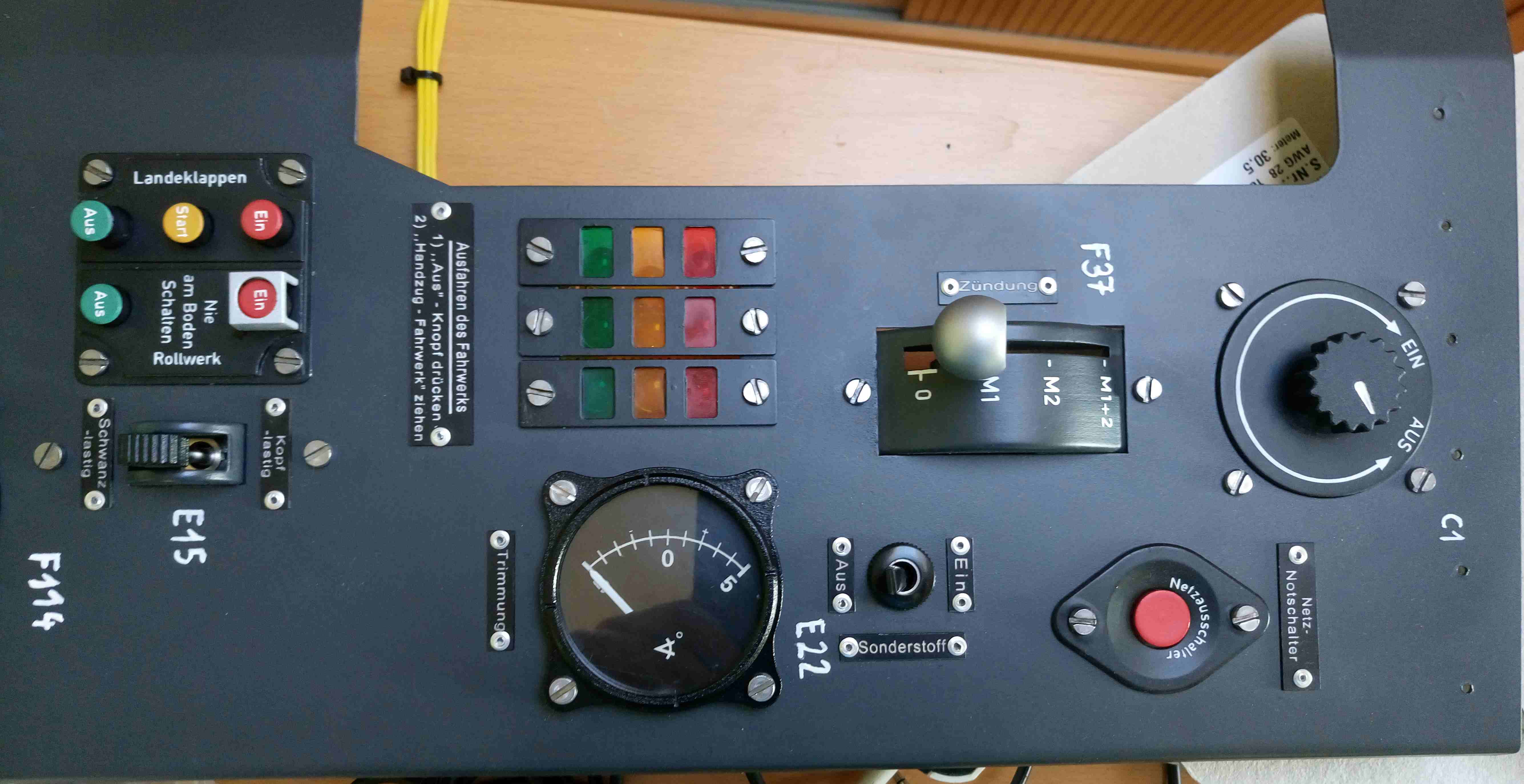
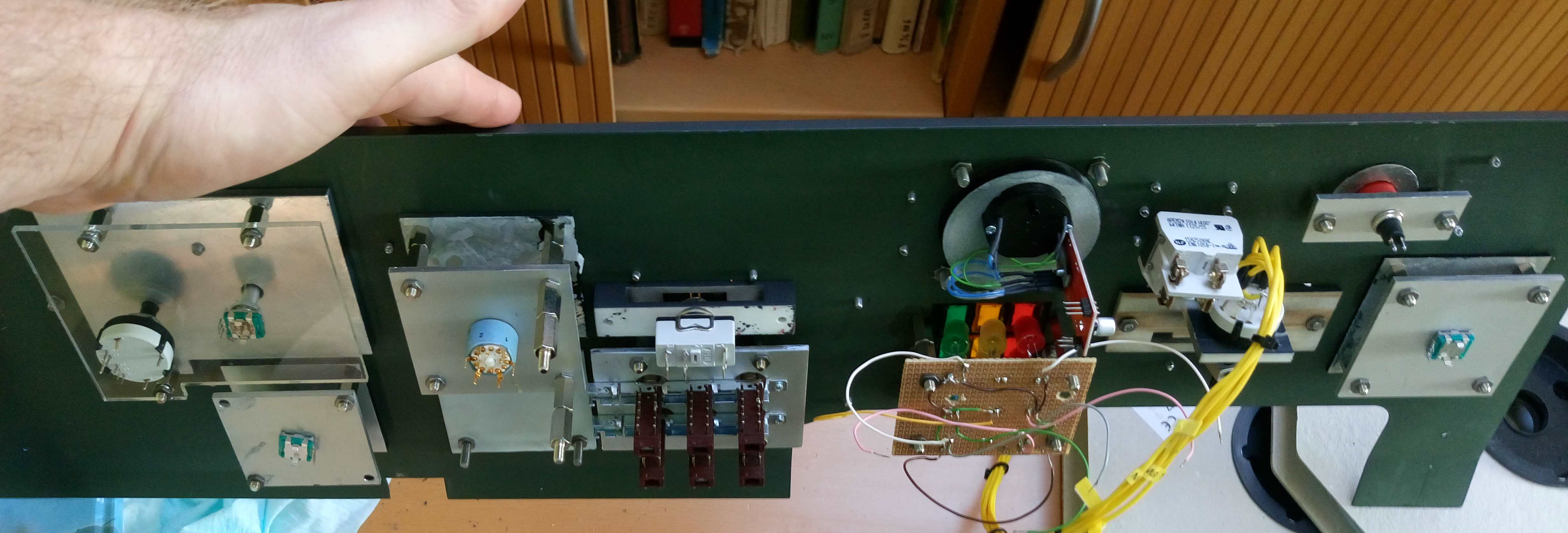
Left console completed :pilotfly: ... Just connect to ICB:music_whistling:
-
I have just finished first two Instruments. Trim indicator and oxygen pressure indicator. Both are already tested and prepared for assembly. See trimm video . I have material for 75% of gauges so during Christmas holidays I will have lot of fun. I have started cooperation with Tekxx so I am now using his ICB RS485 boards and it is working like charm. He did great job for DCS pit builders community. I am now waiting for another 4 pcs of ICB from him and then I can make final assembly of right and left console. I am also in parallel working on another things like cockpit floor and middle console (thx to for dimensions Krupi) so another pictures will come soon…
-
DCS bios change max and min read value of potentiometer i
draken152 replied to draken152's topic in Home Cockpits
Thx:). This will only automaticaly change the max min numbers for map function. But how to get map function working with DCSBios code??? Then it doesnt matter if you put max-min automaticaly or manualy... -
DCS bios change max and min read value of potentiometer i
draken152 replied to draken152's topic in Home Cockpits
I have tried map function but without success.... -
DCS bios change max and min read value of potentiometer i
draken152 replied to draken152's topic in Home Cockpits
Anyone with advice pls:helpsmilie: