draken152
-
Posts
219 -
Joined
-
Last visited
Content Type
Profiles
Forums
Events
Everything posted by draken152
-
Hi all, because my FW190D pit is close to the final stage I am wondering about the displays. I have two possibilities 3 curved big monitors 40" and more or Simpit centurion 270. Currently I am preferring to use centurion but I have some questions: - what are your experience with centurion 270 and DCS, resoluttion, FOV, calibration an so on???worth to buy??? - It is some distributor in europe(there are crazy custom duties in mycountry)??? - have somebody bough it in last year, what is your impression about simpit company, delivery, communication and so on????(I have read some negative experience here) Any advice or experience is welcome:thumbup:
-
Thanks :) Shortly some 8 years as process engineer for assembly lines, now R&D engineering- process specialist, both in compressor for refrigerants business...:pilotfly:
-
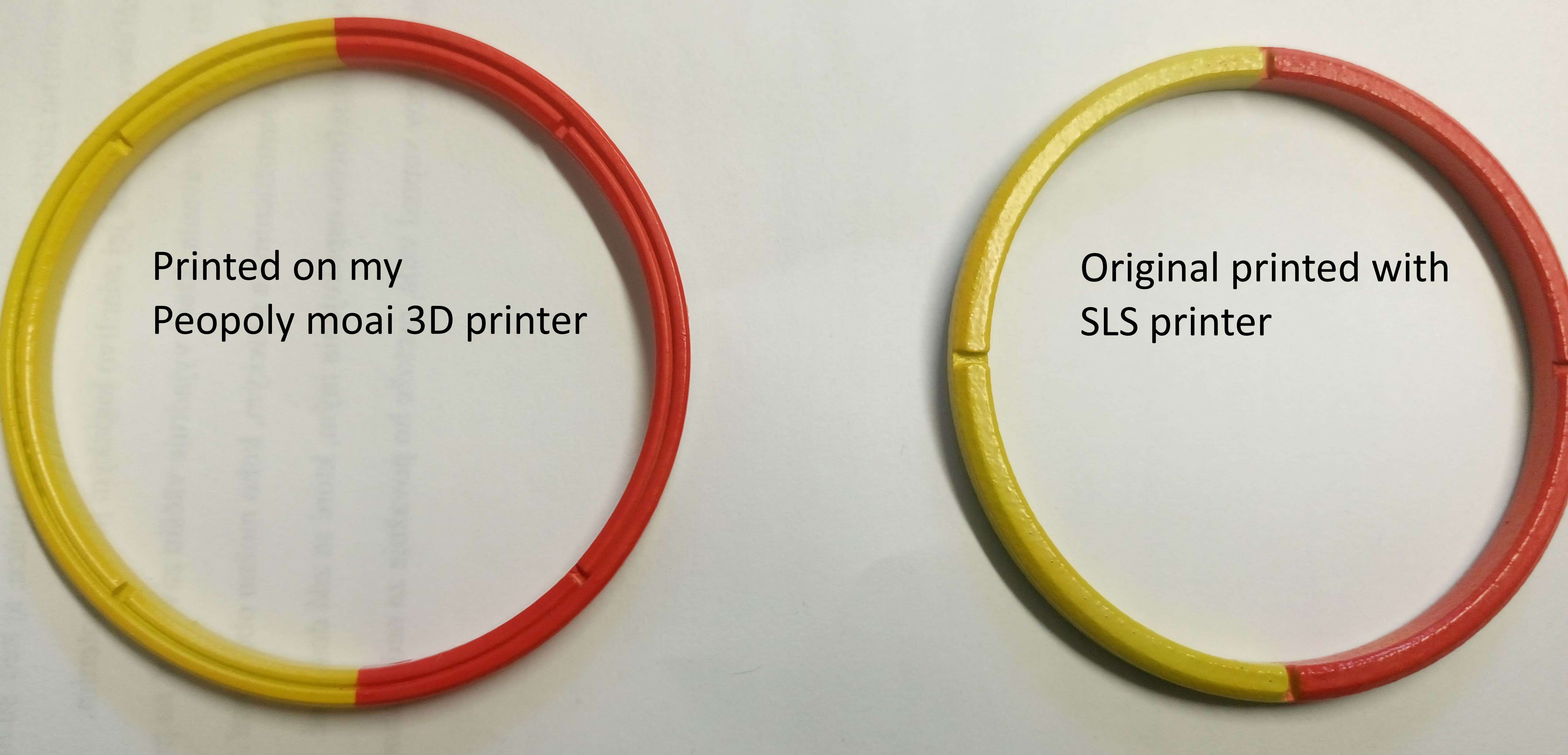
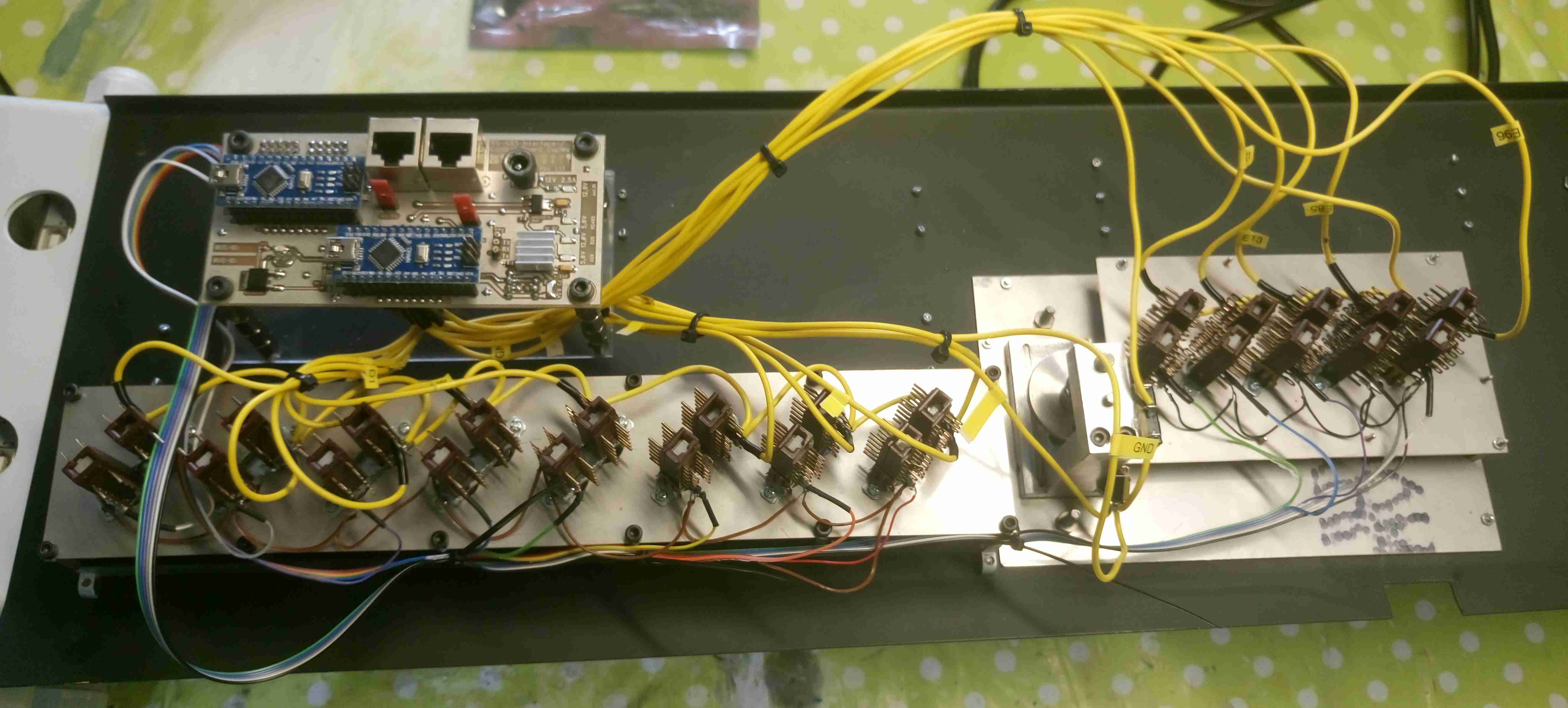
Thanks to all for your kind comments:worthy:.... In meanwhile few things happened :music_whistling: . First of all I have bought SLA 3D printer Peopoly moai what can help me to use more detailed parts and make me independent from suppliers :doh:, also it will be useful for my another projects. You can see the difference on new upper bezel part of gauge, where on SLS It was necessary to reduce details to get good printing result. I am also finishing lower instrumental panel assembly, all parts are separately tested now I need to connect all the stuff together with ICB, so hell of soldering:surrender: Just Oxygen flow indicator is missing, I am already working on its construction....

-
Only PM version of Mig-19 can use RS-2US. R3S only two for Mig-19P, R3R due the difference in radar no.
-

Searching for an volunteer, alfa-testing new DCS-BIOS RS485 transmitters
draken152 replied to Tekkx's topic in Home Cockpits
At the end I was the volunteer :) I am using Tekkx ICB in my pit without any problems(after testing phase I have bought more from him), but still my build isn't completed so I didn't run whole stuff together(max 2 shields/4 Arduinos connected with master). Take look to my build there are lot of photos and also some videos of panels and gauges using ICBs.... Tekkx made also lot of updates to make the ICBs more user friendly in meanwhile. -
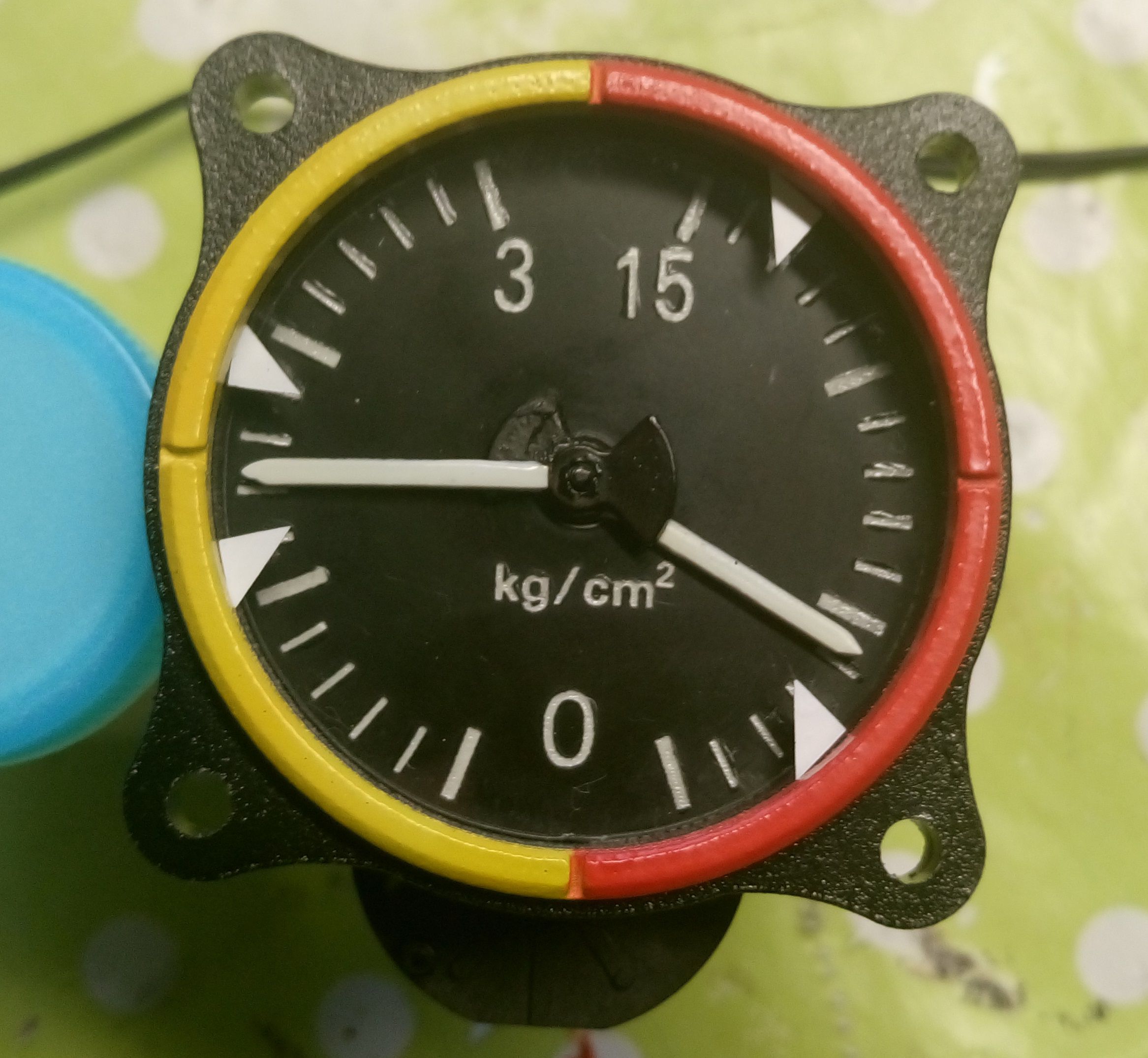
So another indicator complete. This time fuel-oil pressure indicator. It was little bit more complicated due the need of use dual shaft stepper and due the small accident when I have glued shafts together during the arrows assembly. But ok now I know how to disassemble and assemble BKA30D-R5 Stepper Motor :megalol::megalol::megalol:
-
Like usually really nice work:thumbup:
-
DCS-BIOS: problem with first attempt - master caution
draken152 replied to Jocman's topic in Home Cockpits
My advice, I did the same when I have this problem: 1. Check hardware - using simple blinking led program for arduino like this if everythnig OK and working than: 2. Check DCS bios - like Hansolo already wrote use different LED in cockpit or check the code in When you will found root case next step are easy:)... -
I really like you style of work. Nicely done...:thumbup:
-
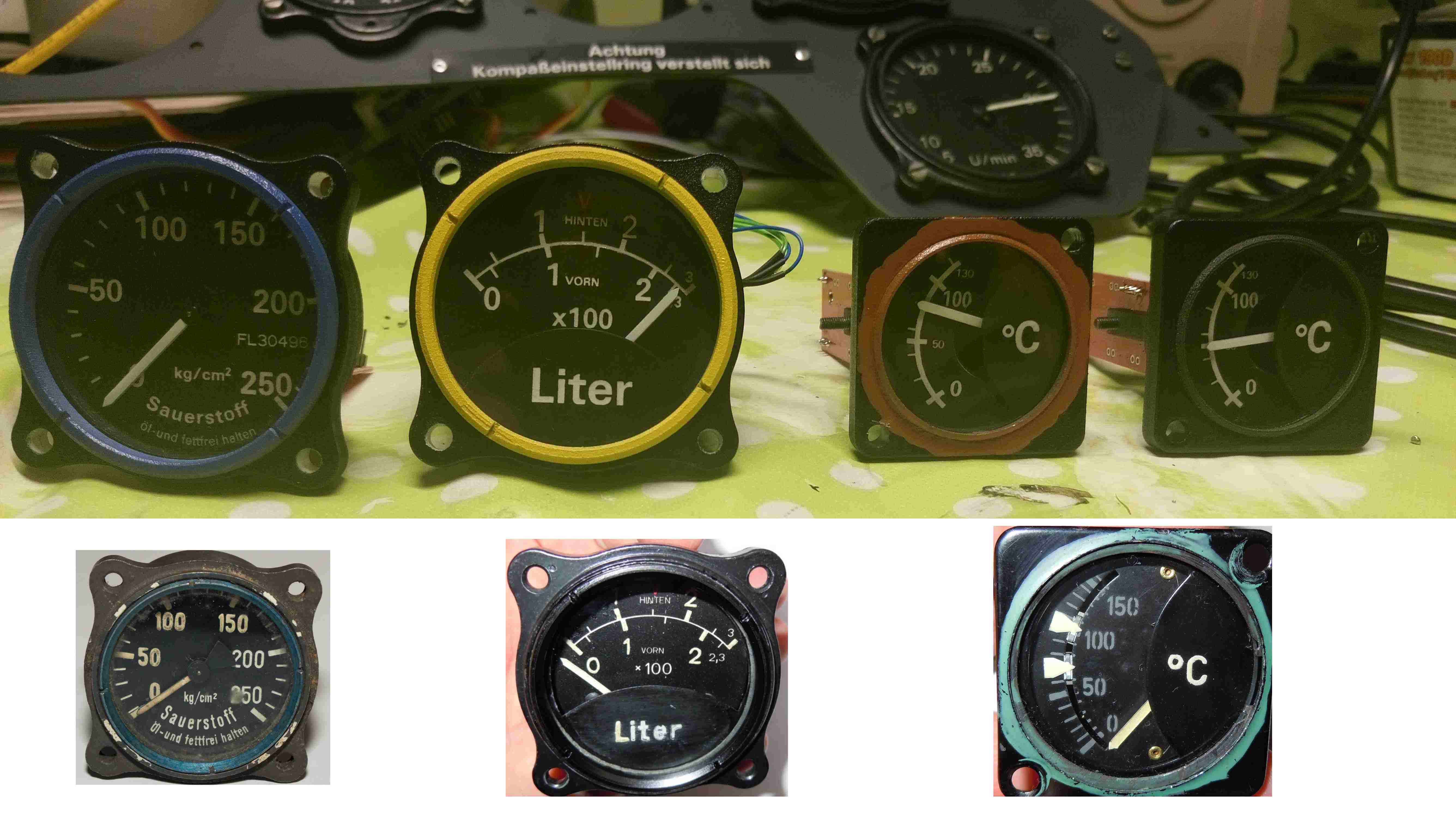
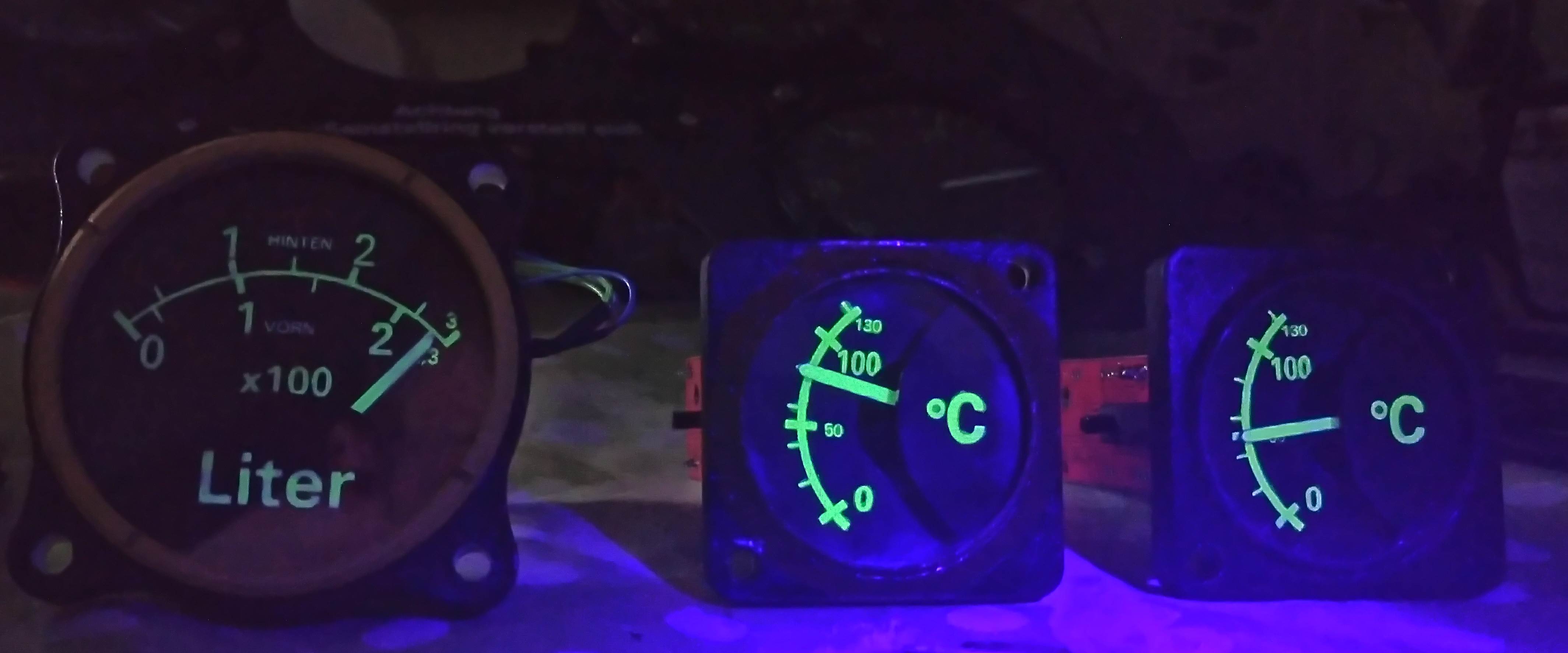
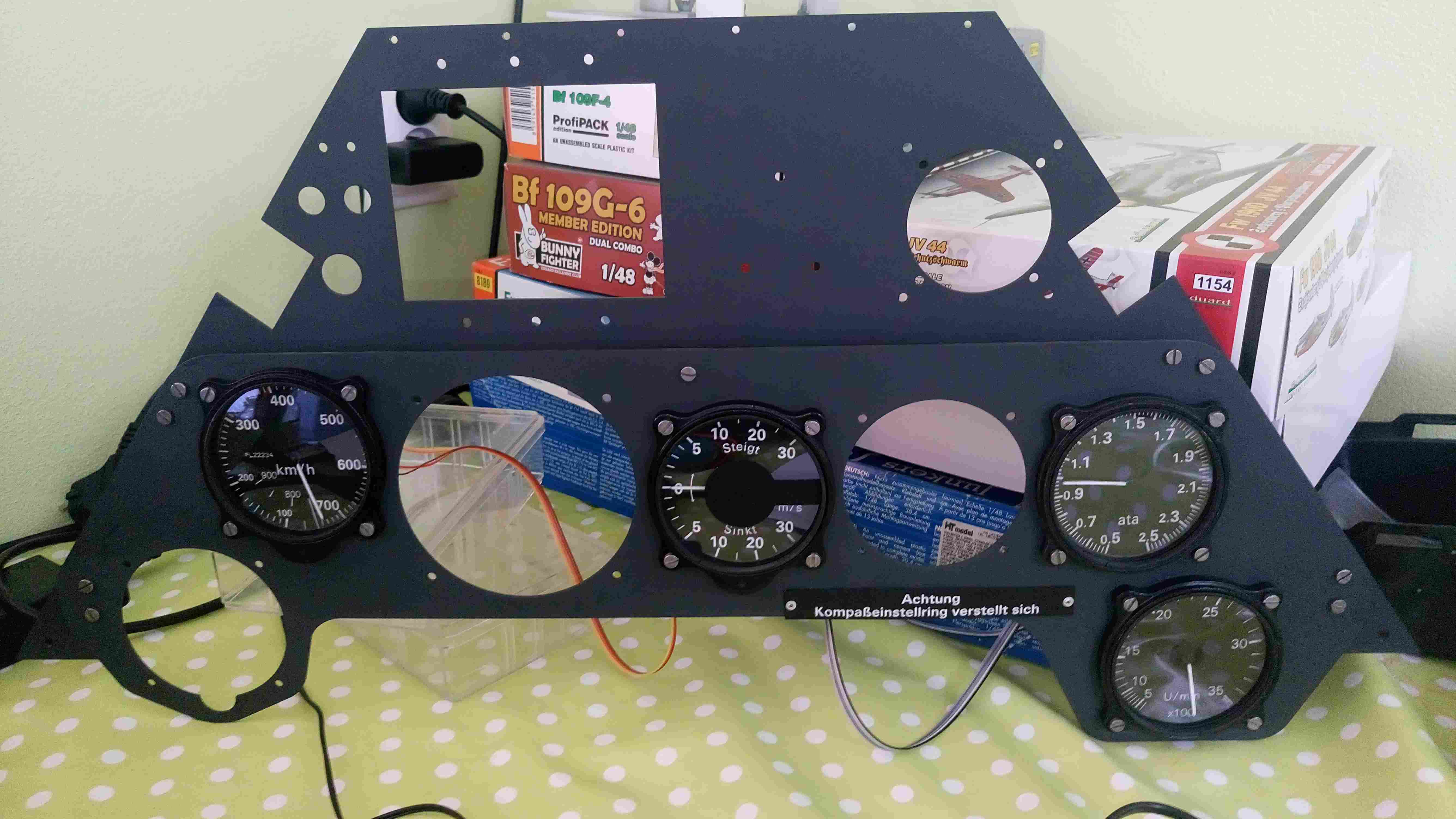
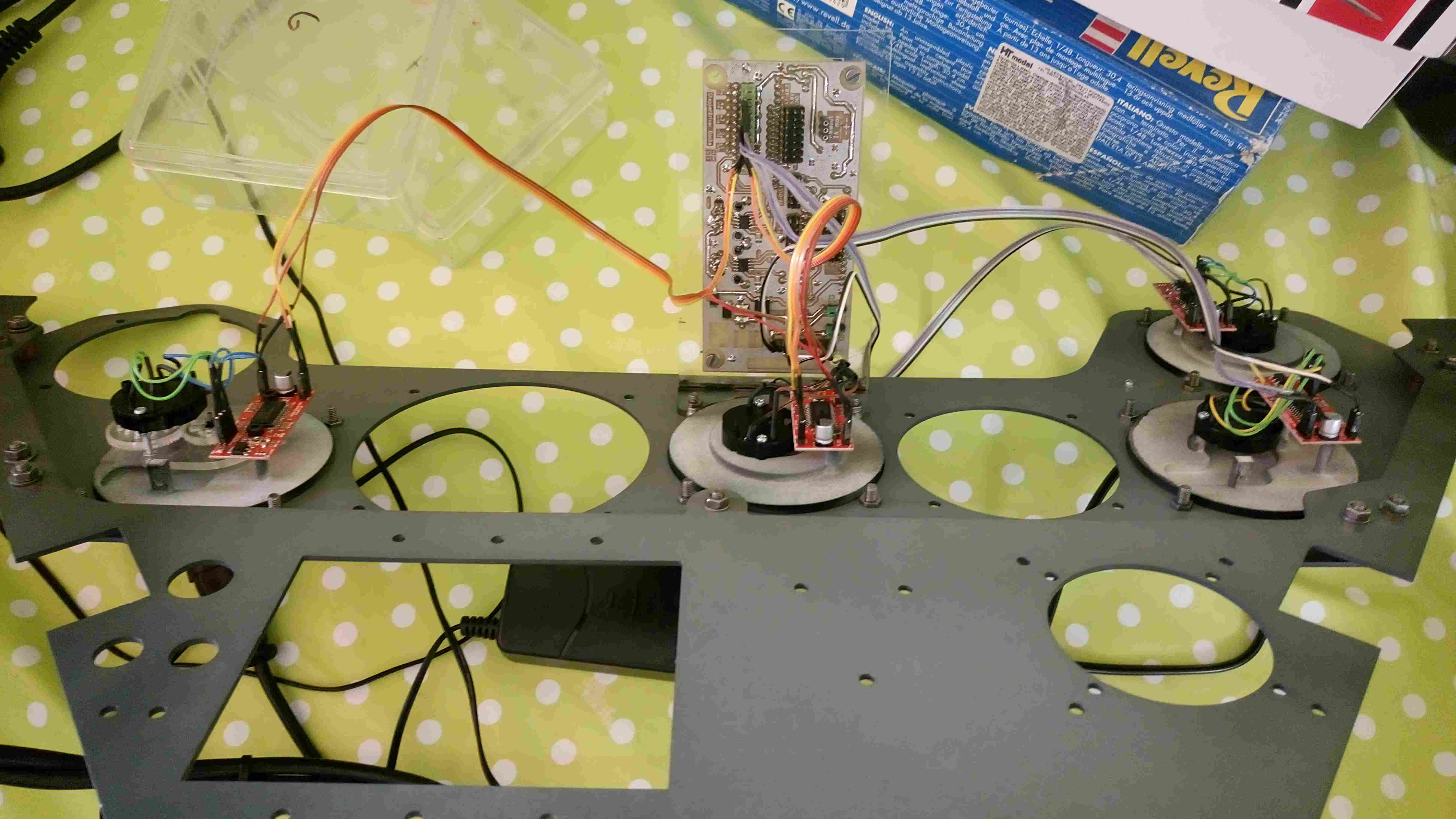
So I am still working on gauges. I have already finished 8 of them:music_whistling: . Thanks to Warhog I have solved problem with multiple steppers on one arduino and even he was sceptic it looks it is working see video of upper instrument panel test. Here are some pictures of completed and tested gauges, illumination is made by UV sensitive colour. In cockpit I will use UV LEDs with non visible light...
-
So I have compared your code to my and I have found my mistake in second stepper instance: /* AccelStepper stepper[color="Red"]2[/color](AccelStepper::DRIVER, 4, 5); // define Vid29Stepper class that uses the AccelStepper instance defined in the line above // +-- arbitrary name // | +-- Address of stepper data (from control reference) // | | +-- name of AccelStepper instance // v v v v-- StepperConfig struct instance Vid29Stepper IAS(0x344e, stepper[color="red"]2[/color], stepperConfig2, [](unsigned int newValue) -> unsigned int { /* this function needs to map newValue to the correct number of steps */ return map(newValue, 0, 65535, 0, stepperConfig2.maxSteps-1); }); }); void setup() { DcsBios::setup(); } void loop() { DcsBios::loop(); } Simply I have forgot to change instance name to different then in instance 1 :music_whistling: Now it is everything working, I am currently running 4 stepper and it seems working without problems (just 10 min of flying).... I will keep testing this week and post video later on... Thanks a lot for help Warhog....:worthy::worthy::worthy: P.S. Wasn't you problem with two steppers connected to acceleration of steppers, because I was not able to use 10000 in none of my gauges with vid29 each time I was loosing steps. Max I am using 5250, but this is probably connected also to arrow material(I am using 0.8mm polycarbonate ) and overall inertia of system... On some gauges I have also found if the data are fluctuating from + to - really fast (what is specific for some gauges for example RPM when you move with throttle forward and backward really fast few times ) I am also loosing steps with acceleration 5250 but with less acceleration is gauge running normally...
-
Hi Warhog, if it is like you have wrote I am really in the troubles :mad:.... I have chose concept using Tekkx boards with Arduino nano due the easy RS485 connectivity. And plan was connect 4 motors to one nano. If this will be not working I have wasted lot of money and time :music_whistling: You can see upper instrumental panel on the pictures no secret, I am using same drivers like you. But still there must be a way how to update original vid29 code for more then one stepper in arduino. Even in original code for vid 29 is writen multiple Vid29Stepper instances can share the same StepperConfig object ... Before I will give up with my concept I need to drink some whisky and also test and prove it is not working:) So if somebody know how to update code please help....
-
Already tried, it didn't help...And due the different adjustment for acceleration and speed for each gauge I need more then one stepperconfig....:dunno:
-
Master is standard code: /* Tell DCS-BIOS this is a RS-485 Master. You will need to flash this to a Mega 2560. */ #define DCSBIOS_RS485_MASTER /* Define where the TX_ENABLE signals are connected. You can connect up to three half-duplex RS-485 transceivers. Arduino Pin RS-485 Transceiver Pin TXn ------------------- DI (driver input) RXn ------------------- RO (Receiver Output) UARTn_TXENABLE_PIN ---- /RE, DE (active low receiver enable, driver enable) If you have less than three transceivers connected, comment out the corresponding #define UARTn_TEXENABLE_PIN lines for receivers that are not present. */ #define UART1_TXENABLE_PIN 2 #define UART2_TXENABLE_PIN 3 #define UART3_TXENABLE_PIN 4 #include "DcsBios.h" void setup() { DcsBios::setup(); } void loop() { DcsBios::loop(); } Code form my first post is working but only for first motor, second one will not even do zeroing. So the part of code added by me for second stepper is wrong but I don't know why, I have just copy stepperconfig and rename it to stepperconfig2 and copied motor instance and changed pin numbers and addressing of instrument. Separately for each motor it was working but together two motors in one arduino not.... :helpsmilie::helpsmilie::helpsmilie:
-
Really nice work. I am already working almost 4 years on my pit and still not done (I hope this year is final year), so you are quit effective :thumbup: Haven't you be thinking about use of projectors with 180° or 270° screen??? For your nice pit it will perfect combination:pilotfly:
-
Hi Guys, I have already finished construction of 8 gauges for my pit, all of them are already fine tuned (steps, speed...) running one gauge on one arduino (for tunning/testing). Now I am trying to implement 4-5 to one arduino by changing of well know code for Vid29, so i can use Tekxx ICB pcb for RS485 communication. This is what I have tried but always only one motor is working (I have added one stepper config and one motor instance) please help:helpsmilie::helpsmilie::helpsmilie: /* The following #define tells DCS-BIOS that this is a RS-485 slave device. It also sets the address of this slave device. The slave address should be between 1 and 126 and must be unique among all devices on the same bus. */ #define DCSBIOS_RS485_SLAVE 6 /* The Arduino pin that is connected to the /RE and DE pins on the RS-485 transceiver. */ #define TXENABLE_PIN 2 #include <AccelStepper.h> #include "DcsBios.h" struct StepperConfig { unsigned int maxSteps; unsigned int acceleration; unsigned int maxSpeed; }; class Vid29Stepper : public DcsBios::Int16Buffer { private: AccelStepper& stepper; StepperConfig& stepperConfig; unsigned int (*map_function)(unsigned int); unsigned char initState; public: Vid29Stepper(unsigned int address, AccelStepper& stepper, StepperConfig& stepperConfig, unsigned int (*map_function)(unsigned int)) : Int16Buffer(address), stepper(stepper), stepperConfig(stepperConfig), map_function(map_function), initState(0) { } virtual void loop() { if (initState == 0) { // not initialized yet stepper.setMaxSpeed(stepperConfig.maxSpeed/4); stepper.setAcceleration(stepperConfig.acceleration/4); stepper.moveTo(-((long)stepperConfig.maxSteps)); initState = 1; } if (initState == 1) { // zeroing stepper.run(); if (stepper.currentPosition() <= -((long)stepperConfig.maxSteps)) { stepper.setCurrentPosition(0); initState = 2; stepper.moveTo(stepperConfig.maxSteps/2); } } if (initState == 2) { // running normally if (hasUpdatedData()) { unsigned int newPosition = map_function(getData()); newPosition = constrain(newPosition, 0, stepperConfig.maxSteps); stepper.moveTo(newPosition); } stepper.run(); } } }; /* modify below this line */ /* define stepper parameters multiple Vid29Stepper instances can share the same StepperConfig object */ struct StepperConfig stepperConfig = { 4320, // maxSteps 7000, // maxSpeed 5250// acceleration }; struct StepperConfig stepperConfig2 = { 4320, // maxSteps 7000, // maxSpeed 5250// acceleration }; // define AccelStepper instance AccelStepper stepper(AccelStepper::DRIVER, 6, 7); // define Vid29Stepper class that uses the AccelStepper instance defined in the line above // +-- arbitrary name // | +-- Address of stepper data (from control reference) // | | +-- name of AccelStepper instance // v v v v-- StepperConfig struct instance Vid29Stepper verticalspeed(0x3450, stepper, stepperConfig, [](unsigned int newValue) -> unsigned int { /* this function needs to map newValue to the correct number of steps */ return map(newValue, 0, 65535, 0, stepperConfig.maxSteps-1); AccelStepper stepper(AccelStepper::DRIVER, 4, 5); // define Vid29Stepper class that uses the AccelStepper instance defined in the line above // +-- arbitrary name // | +-- Address of stepper data (from control reference) // | | +-- name of AccelStepper instance // v v v v-- StepperConfig struct instance Vid29Stepper IAS(0x344e, stepper, stepperConfig2, [](unsigned int newValue) -> unsigned int { /* this function needs to map newValue to the correct number of steps */ return map(newValue, 0, 65535, 0, stepperConfig2.maxSteps-1); }); }); void setup() { DcsBios::setup(); } void loop() { DcsBios::loop(); }
-
I am glad you are back on the track :thumbup: ... You did amazing job for DCS pit builders community and I am looking forward to see results of your next work :worthy: . Congrats to new work ... All the best
-
Small progress after longer time. Right console completed and tested:music_whistling:.
-
Nice work :thumbup::thumbup::thumbup:
-
On-on you can use without editing lua, but you can use only 16 with BU0836X (each switch connected to two BU0836X inputs, one for on position second for off position + ground). I strongly recommend to use on-of system and editing lua, look here for details. You can use all 32 inputs with this system... btw. for on-off you can use switches what you already had, but connected only to one input :)
-
During my work on Artificial Horizon for my pit I have found one thing where I need advice. In DCSmanual is written: But in DCS the horizon bar is rotating in bank direction contentiously 360°. So where is mistake ??? Or did I misunderstand something:music_whistling: This is crucial for my Artificial Horizon design so please if some one have additional info....
-
For RS485 you can also use existing plug and play solutions (ASBIS or Tekxx), look here
-
Nice work !!!:thumbup:
-
Really nice work :thumbup:
-
Strange, Ian didn't answered this...:(