draken152
-
Posts
219 -
Joined
-
Last visited
Content Type
Profiles
Forums
Events
Everything posted by draken152
-
Sokol thx for links, really inspiring. I like the use of rotary dampers. To Elmo: I mean the paper holder on upper side of console see picture. I have some clues but I am not sure:dunno:

-
Throttle lever painted and assembled. Also rest of right side ,,paper holders“ have arrived. Does anyone know for what was used paper holder on the rear of right console near pumps switch??? I have lot of small parts prepared for test fitting and painting, but It is at least starting to look like FW 190D pit:music_whistling:
-
Again after longer time some update. I am working on plenty of small things, with feelings,, nothing is visible" :cry:... Mostly I am spending my time by designing rudder pedals mechanism, I want to have it so close to real one as possible, so base of movement is from upper side no on the floor of pit...That is making it trickier:chair:. You can see basic idea on pictures, pedals are just temporary model I am working on new one better suited for my technology (milling, drilling laser cutting) , this one need casting....Also upper cover of instrument panel and some small parts have arrived, you can see how it looks during test fitting...
-
I know your work VO101_MMaister, really impressive… It was inspiration for me :thumbup:
-
Left console test fitting. Second pilot is awaiting first flight:pilotfly:....
-
Thanks, I hope my instrument panel will be so nice like yours Cripple :thumbup:
-
Painting in progress:pilotfly:
-
It takes a while.... In meanwhile I have assembled EZ 42 adjusting unit...
-
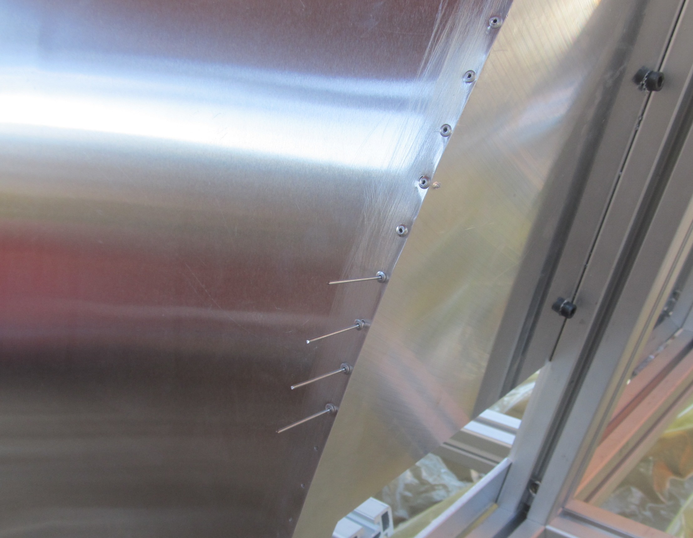
My wife, together with my son is out from home for few days so I have utilized free time :pilotfly:. I disassembled my pit and took it out from house for riveting and painting. My first idea was to screw outside plating of pit with M2 screws, but now I have drilled new holes for rivets. It looks much better:thumbup:... Now I am out of rivets (till today I have used 320pcs), so tomorrow I must buy some and then the painting of main pit parts can start (base primer – paint - varnish )....
-
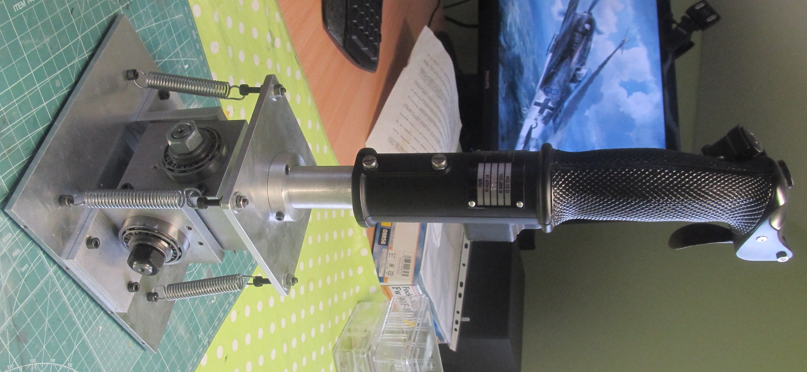
So some small progress stick is assembled in cockpit. Now I am preparing cockpit for painting of the base parts. Unfortunately I am really short of time few last weeks:mad:…
-
Hi endaro, here is direct lin to shop http://racvonka.cz/rele-a-spinace/isostaty.html. I have bought isostats number 21 (for right console double switches) and isostats number 14 (segment with 4 switches so it must be modified) for ger switch. For circuit braker you can use any bush button (also in original FW 190 schematic it is push button) I have used PS-11 with custom made button http://www.distrelec.de/en/push-button-mains-switch-valueline-ps-11/p/11071441.
-
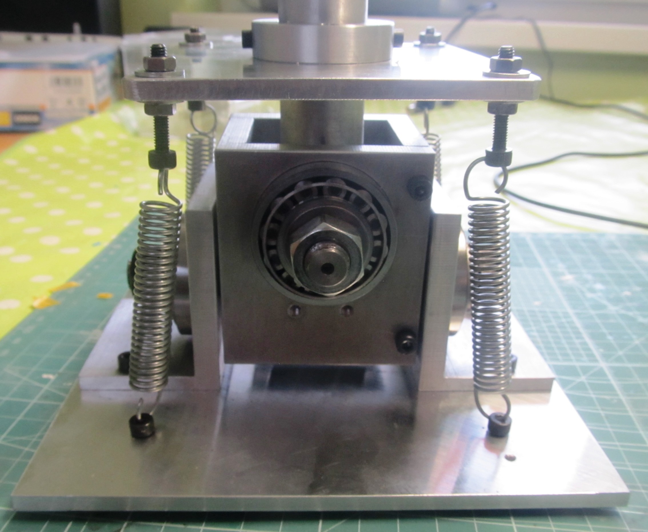
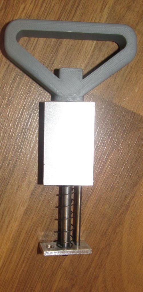
The basic parts are tapered bearings for easily setting of radial and axial clearance. Rest is my custom design. Movement angles are according the values mentioned in original FW 190 manual (it is around 20° I dont know it from memory). There are missing the magnets at the end of shafts and PCBs with hall sensors (and also cover parts)… And good chosen background, man:megalol:
-
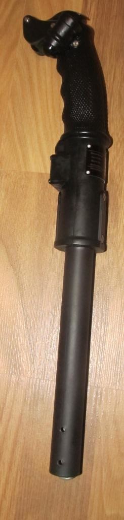
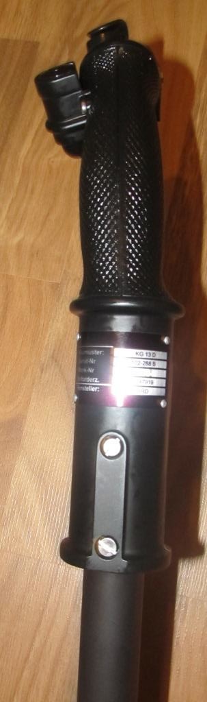
Here is current status of new design of consoles, and assembled grip base. Left console is almost competed (just knobs and some details are missing, but layout is OK). Grip base need some small adjustment but should be OK (KG 13 is assembled without extension):pilotfly:... fw190dcockpit2.pdf
-
Hi Endaro, If I understand it right you are working on this project as team, so you have big advantage you can work on task in parallel... I have planned my project to 3 phases: - Mechanical design and assembly - Signal export to simulator (so electronic for all switches ) - Signal inputs from simulator (so gauges) I am currently in design phase and assembly of parts so I dont have currently experience with gauges but you can found many good advices here in forum or you can ask some guys building A10C pits directly...I have study these a lot and my plan is to go for vid 29 and vid 60 stepper motors + ardunio but that is everything what can I say right now... About dimensions it depends on you how close to real FW 190 you want to be. For most of the gauges you can find drawings at http://www.deutscheluftwaffe.de , also there are some blueprints available from different webs. From my experience proportion use as main sources isn’t really good approach (see real drawing of gauge you have post), I use proportion only when it is necessary and only on small parts with some known part near (for bigger parts you must count with errors due distance from camera objective and perspective of photo).
-
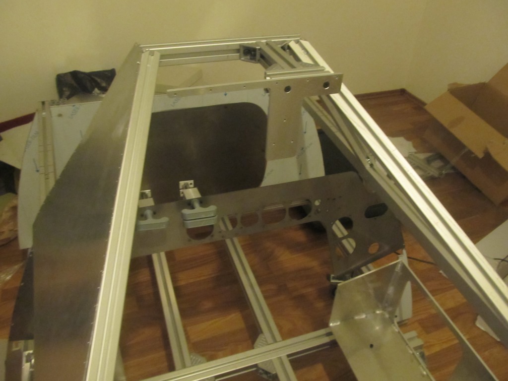
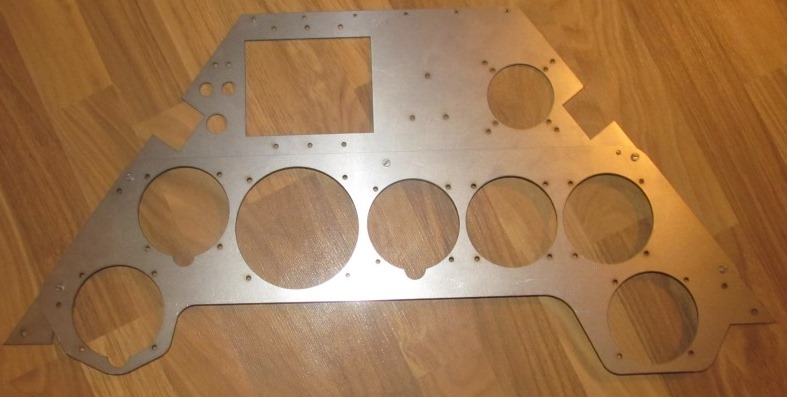
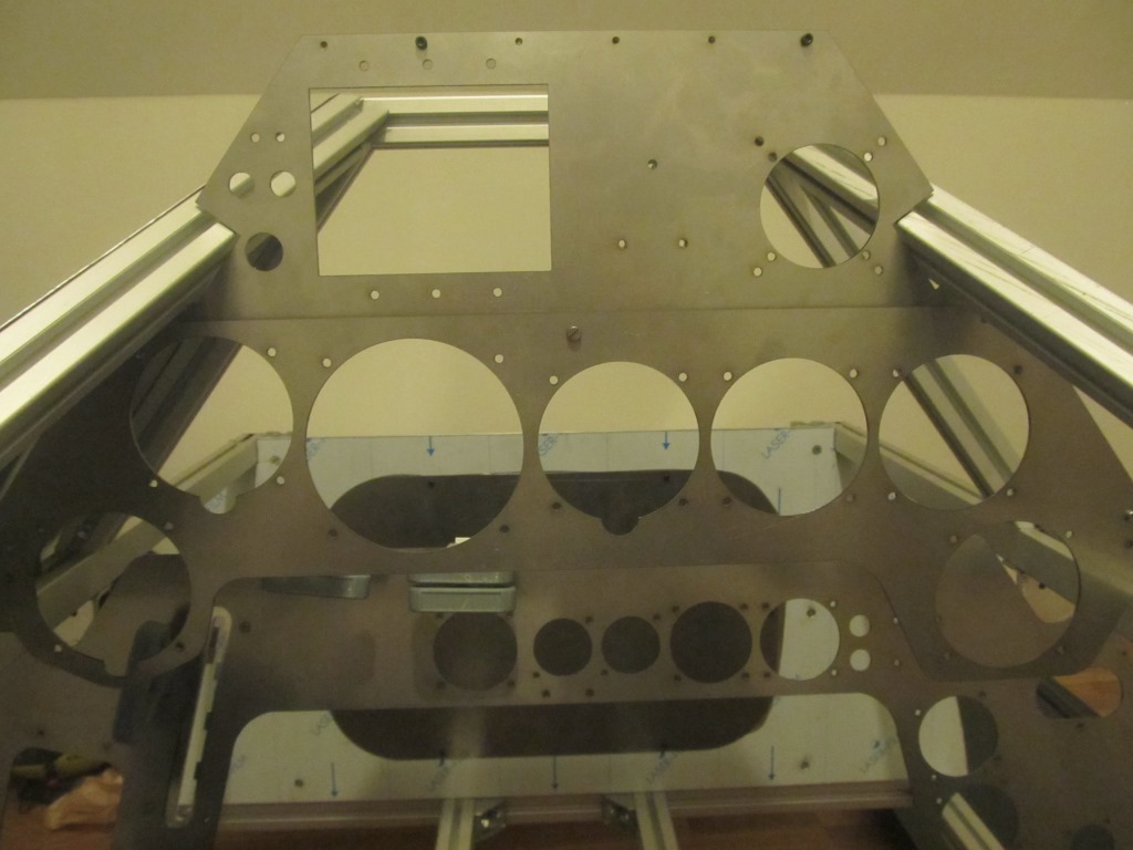
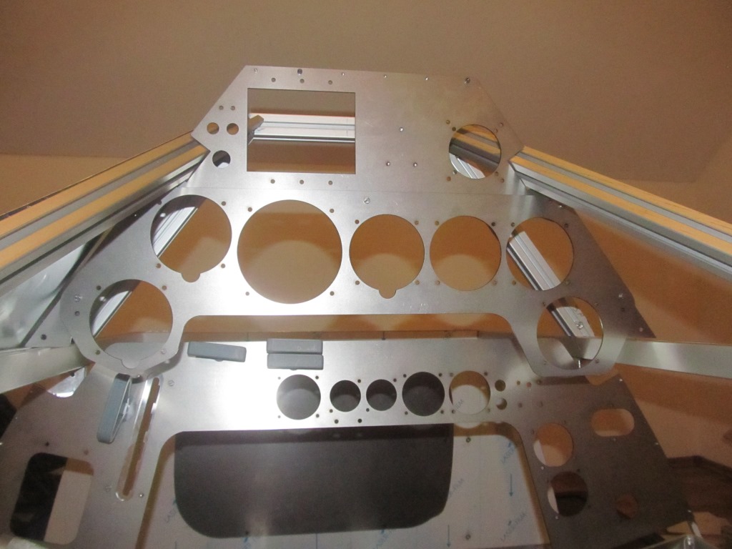
Upper instrument panel has arrived. I made aluminium strengthening as base for gunsight :megalol: (yes EZ 42 is also planned). I have made also new bottom instrument panel. I was not satisfied with look of older version…Base for fuel tank control lever is assembled together with landing gear emergency lever.
-
Thanks Cripple. Now I am working on upper insruments panel. I am also looking forward to see progress of your pit...
-
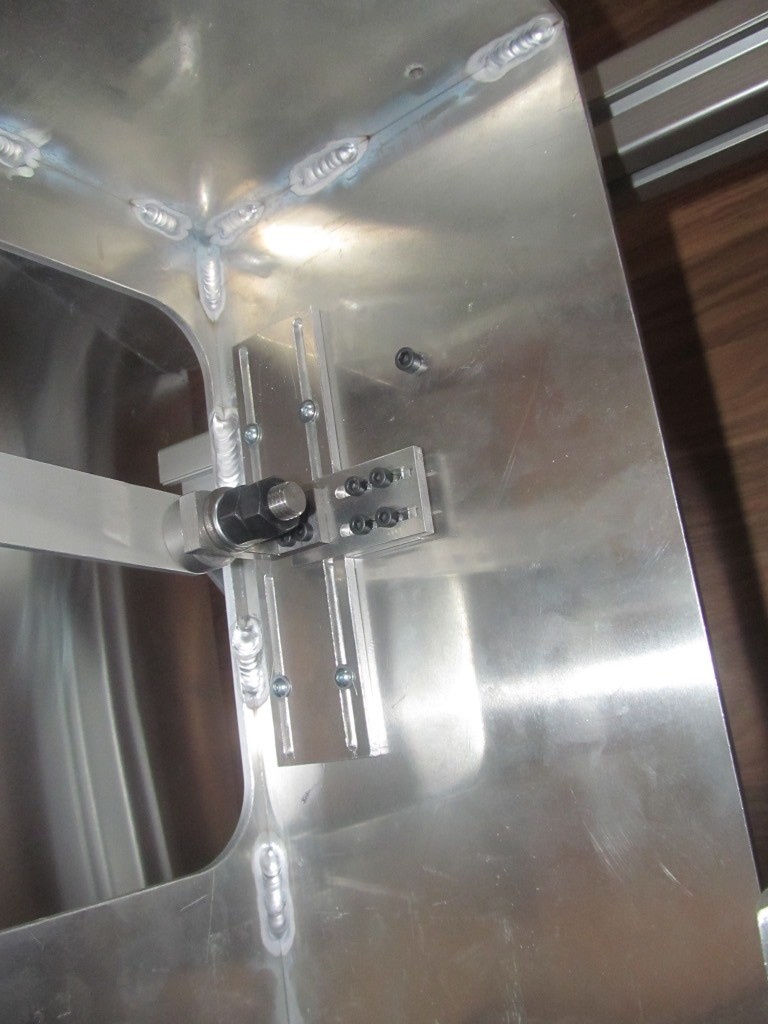
Throttle lever is on the place. I made new easy adjustable bases for it.
-
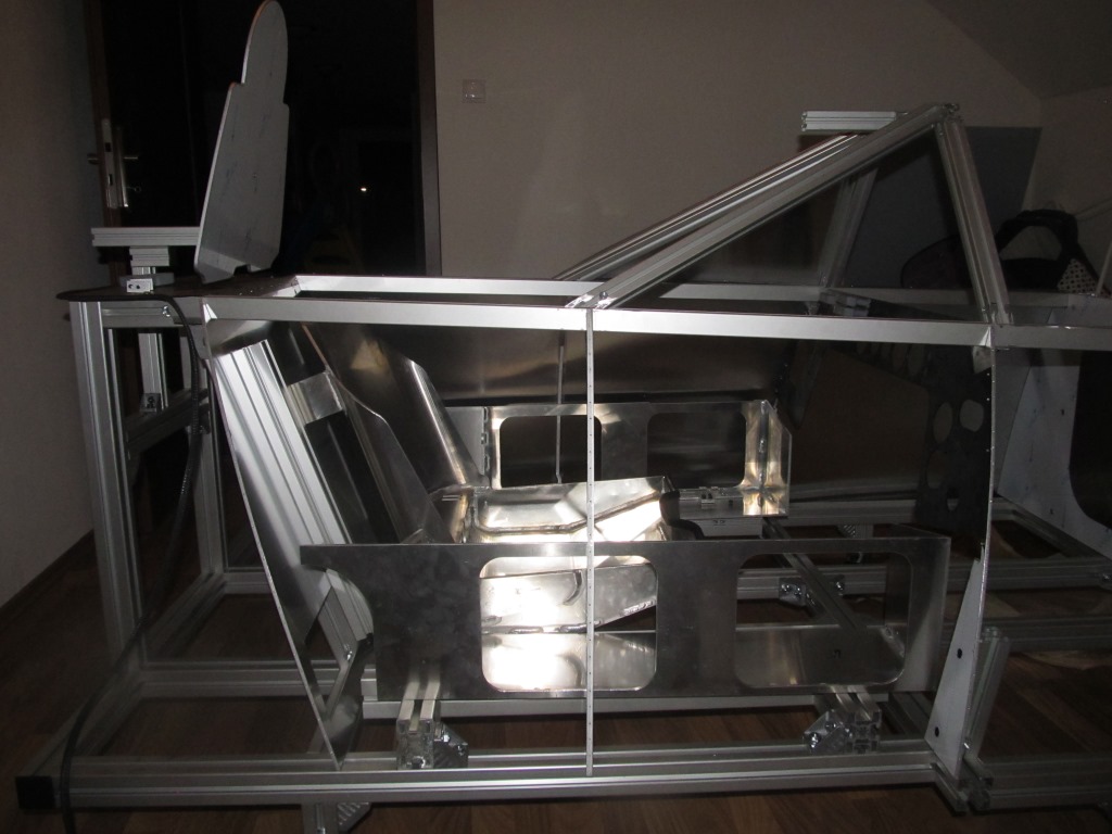
Left side of coating completed. Seat is assembled on final place. New aluminium bases for consoles are roughly assembled. Now I am testing mechanisms for bottom instrument panel levellers.
-
You are right but only when my wife isnt at home :music_whistling:
-
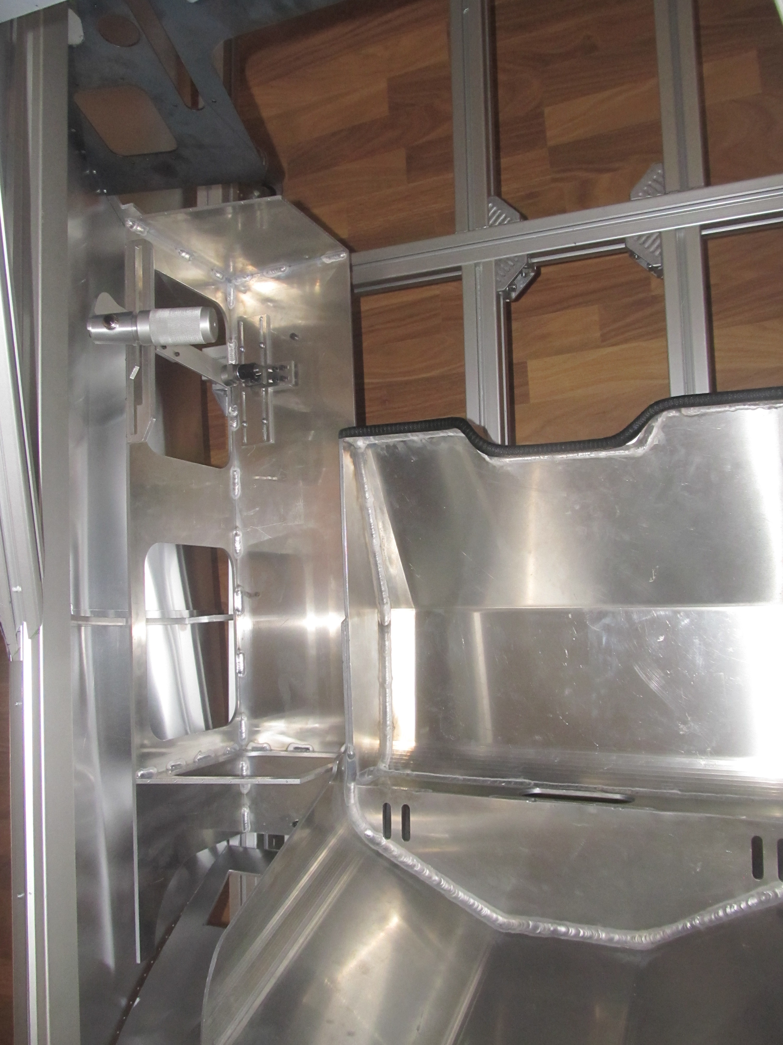
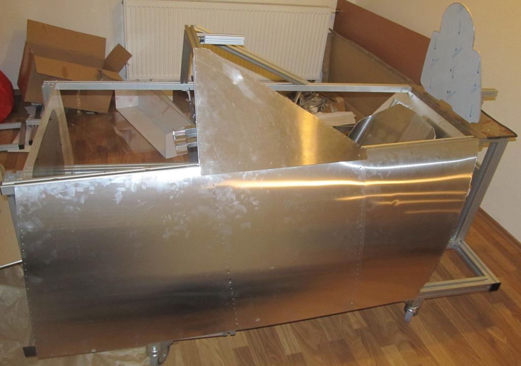
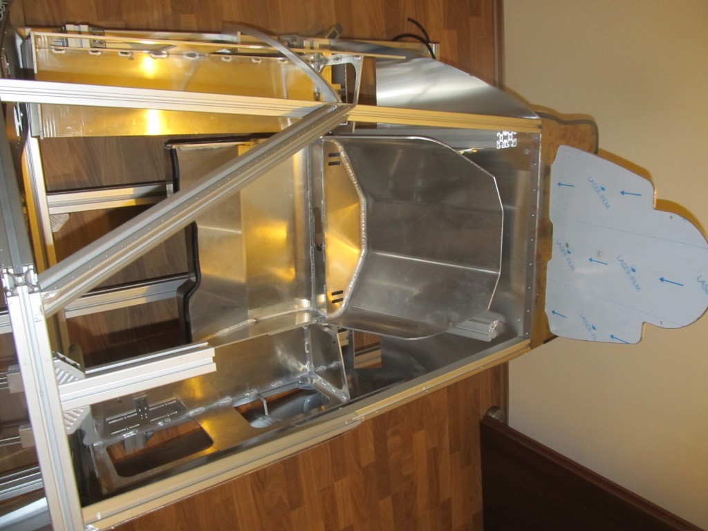
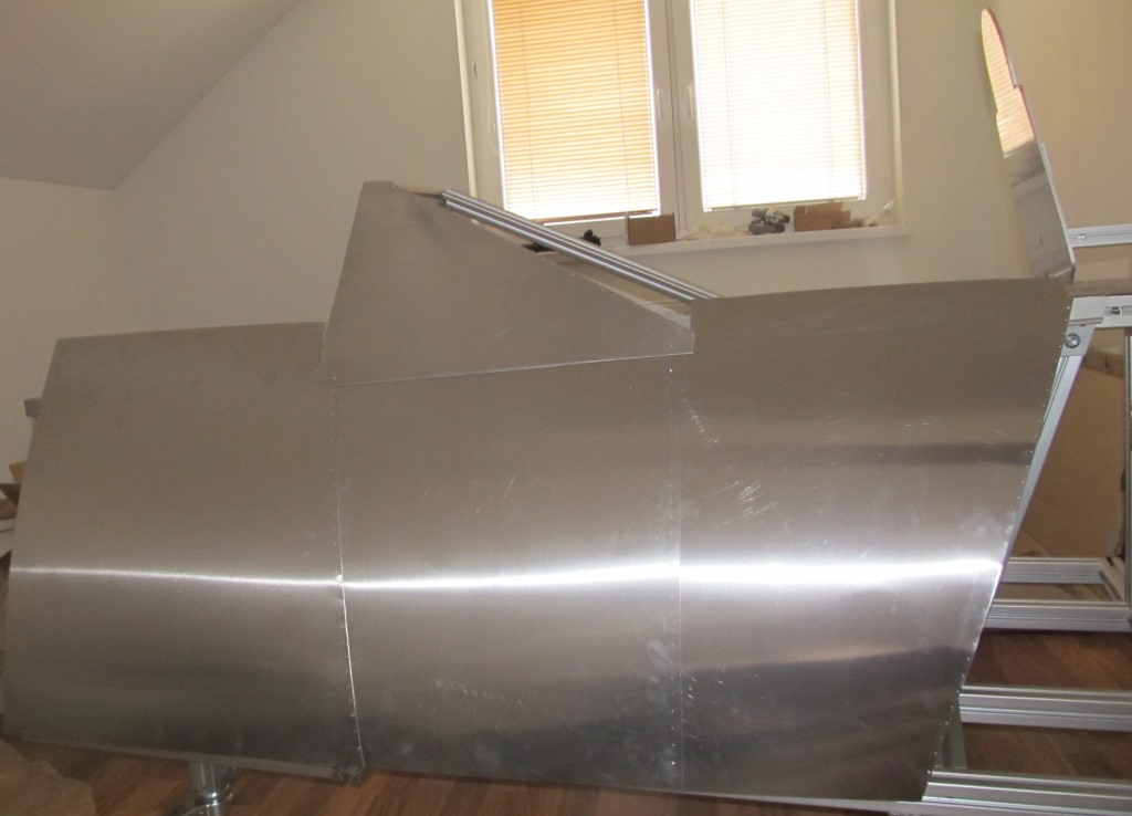
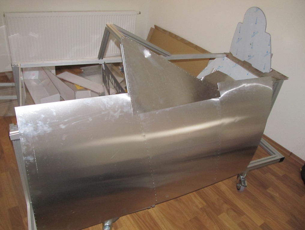
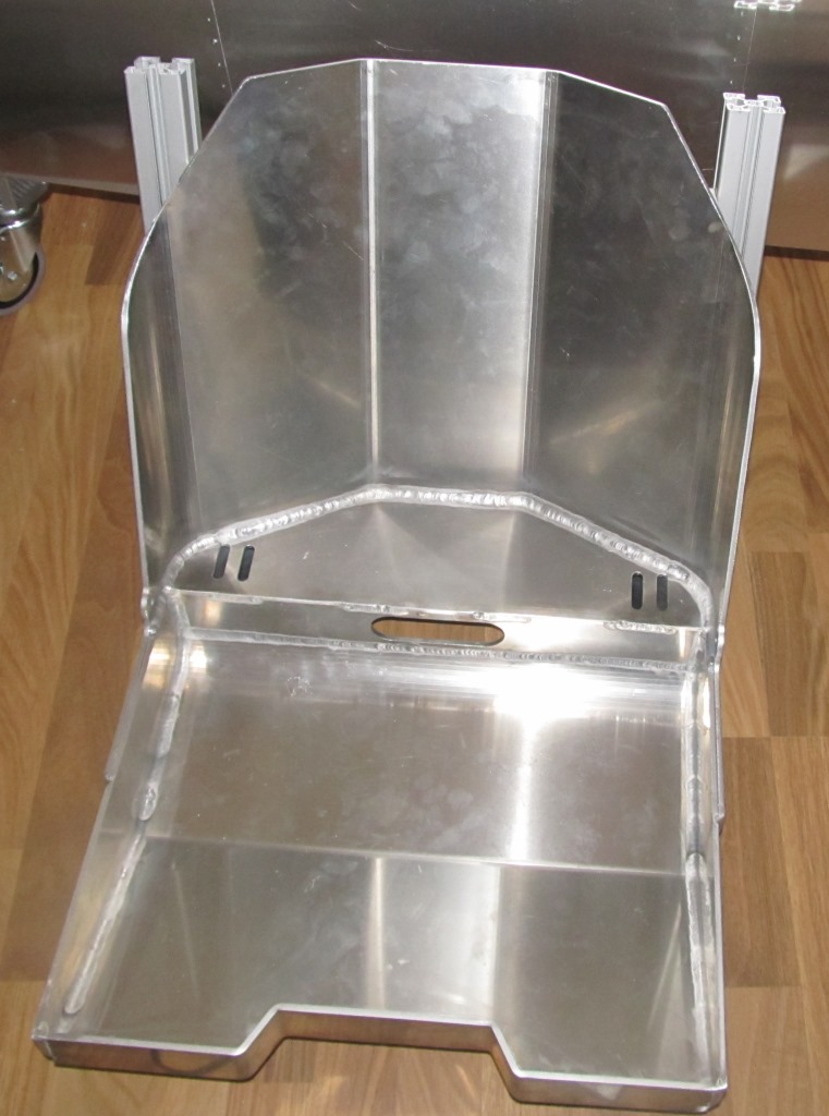
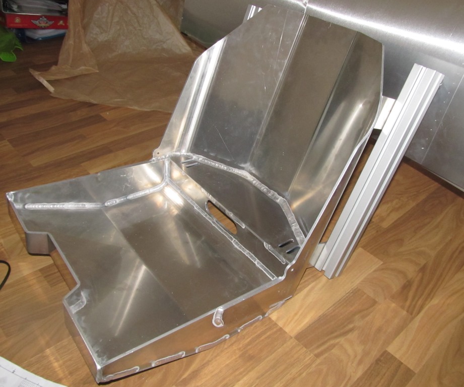
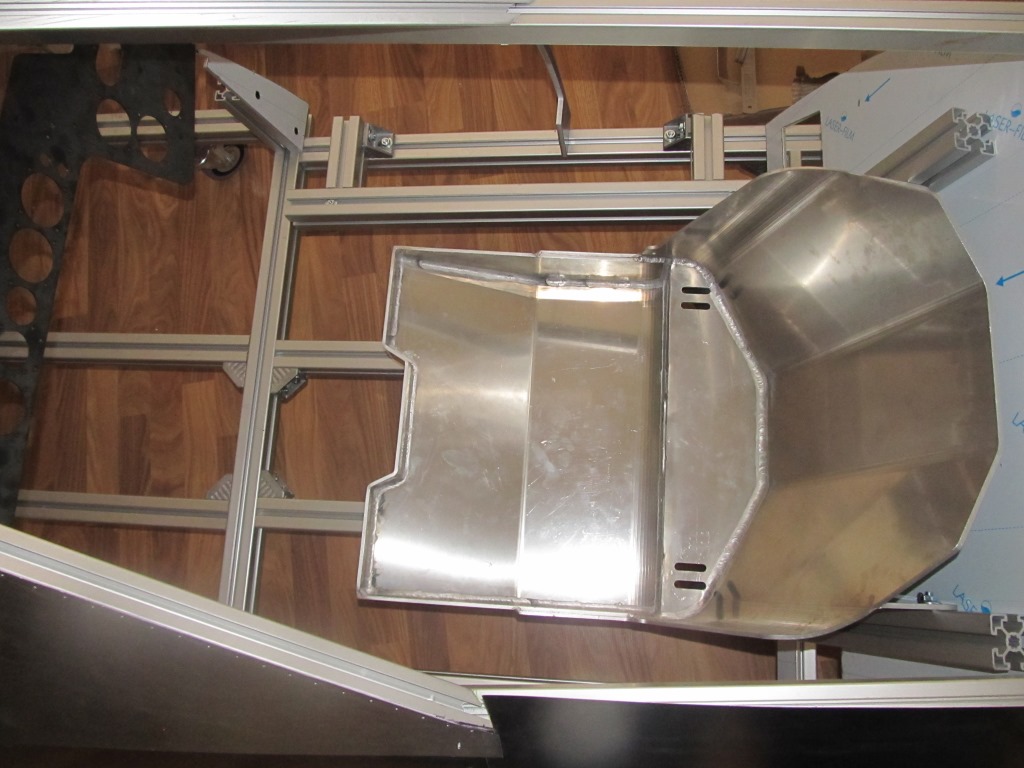
I have roughly assembled aluminium coating on left side of cockpit, I think it is looking much better than polycarbonate:pilotfly:. Upper edges are still not cut because cockpit is too big so I am working on solution for easy disassembly (my initial plan was to simply bend upper part of aluminium). In meanwhile one of my friends made pilot seat according my plans:thumbup: (it is nice when you have someone who is able to weld aluminium), it is made from 5mm aluminium bended and welded... I was trying to be so close to original shape of seat as was possible but original seat was stamped so some change due different technology was necessary....Now I am waiting for new consoles bases, i have scraped original ones from polycarbonate and now I will have them also from 5mm aluminium. On last photo is my inspiration...
-
Subscribed, really nice build. I hope there will be more DCS WW2 warbirds pit builds like yours… :pilotfly:
-
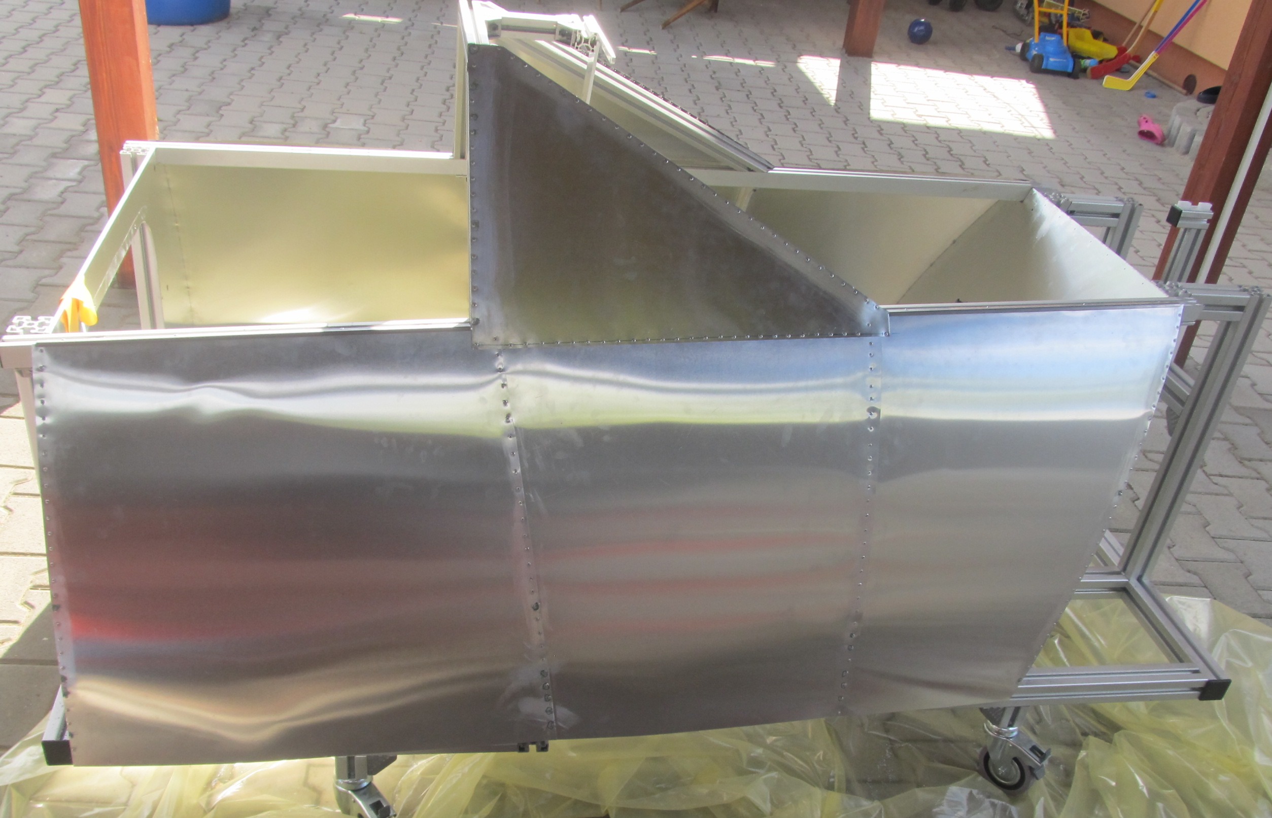
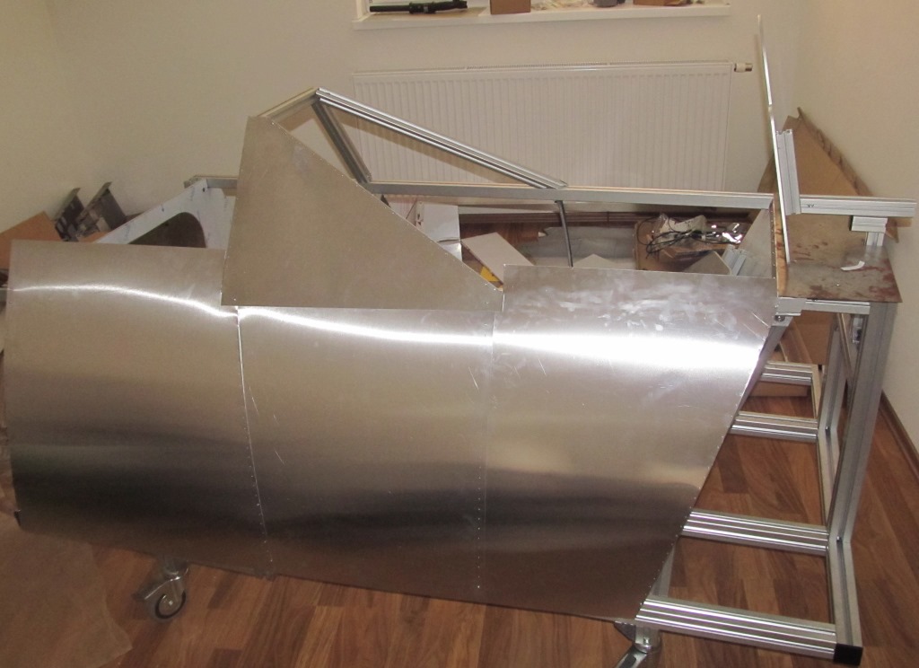
Thank you. So current situation: Polycarbonate was disassembled due the poor durability:mad:, I have change my opinion and ordered 0.6mm aluminium plates for fuselage coating, I think result will be much better...Consoles bases are on the place. I meanwhile I have received package from Russia:joystick:...
-
Hi it is looking promising.:thumbup: I am still not convinced how to get life to my FW 190D cockpit gauges . This will be great option... I wish you luck and patience in your work....What is your ETA for first release... I am still at mechanical development and construction of my pit so I have time for final decision about electronic:prop::prop:...
-
Some progress, coating of fuselage is on place. It is made from 0.75 polycarbonate and it is holding on approximately 400 screws :bomb:(only few are assembled currently).
-
Hi Toxaq, The name of the switches is Isostat/Izostat (you can found them in both written form). Only one can be switched on but you can found also different setups (momentary...). I don’t know if they are still produced they were really common during 80s -90s in the middle Europe communism countries (Czech, Poland, Slovakia). I have bought it in Czech http://racvonka.cz (only in Czech language). I know there are some similar switches produced in Britain and also in China.